
Related Manuals for Tiso Speed Gate Series


Summary of Contents for Tiso Speed Gate Series
- Page 1 "TiSO-PRODUCTION" LTD WAIST-HIGH TURNSTILES Speed Gate series SLIDE with folding leaf OPERATION AND INSTALLATION MANUAL 2023 AUIA.180 rev.1.0 UKRAINE...
-
Page 2: Table Of Contents
CONTENTS INTRODUCTION ................................3 WARNINGS TO THE CUSTOMER ON SAFE OPERATION OF THE TURNSTILE ..........4 1. DESCRIPTION AND OPERATION ........................... 5 1.1 General Information and Purpose ........................5 1.2 Specifications ..............................6 1.3 Configuration and Scope of Delivery......................... 7 1.4 Design and operation ............................ -
Page 3: Introduction
INTRODUCTION This Operation Manual (hereinafter referred to as OM) covers the "SLIDE" type waist-high turnstile (hereinafter referred to as the "turnstile"). The Operation Manual contains information about design, specifications, installation for proper operation and maintenance of the turnstile. This Operation Manual is prepared in compliance with the specification requirements ТU U 28.9- 32421280- 005:2018. -
Page 4: Warnings To The Customer On Safe Operation Of The Turnstile
WARNINGS TO THE CUSTOMER ON SAFE OPERATION OF THE TURNSTILE These warnings are designed for ensuring of safety during operation of the turnstile to prevent violation of safety characteristics by improper installation or operation. These warnings are aimed at drawing attention of the customer to safety problems. -
Page 5: Description And Operation
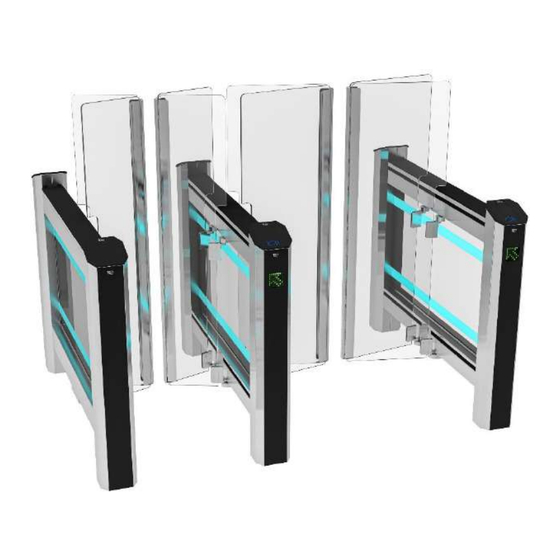
1. DESCRIPTION AND OPERATION 1.1 General Information and Purpose 1.1.1 Purpose: The Slide turnstile with folding high leaves guarantees effective protection and is a stylish original solution for your object. The motorized turnstile is designed for pedestrian movement control at access points of industrial enterprises, banks, stadiums, administrative facilities etc. -
Page 6: Specifications
1.1.3 The turnstile component identification codes are specified in Table 2. Table 2 Max. Dimensions, mm, Order code Description of the turnstile component Н weight, kg One side cabinet Slide-1.1 Master AUIA.180.1 Т3.КСD.xD Slide-1.2 Slave AUIA.180.1 1500 1432 Double side cabinet Т3.КСD.xD.X 100* Slide-2 Master/Slave AUIA.207-03.2... -
Page 7: Configuration And Scope Of Delivery
1.3 Configuration and Scope of Delivery 1.3.1 The turnstile modification depends on the number of lanes: 1) For arrangement of single access way the turnstile "Slide-1" is a set of two similar single side cabinets (Master and Slave) with one folding glass leaf (reference designation Т3.КСD.ХD);... -
Page 8: Design And Operation
1.3.4 The turnstile material of manufacture is carbon steel subject to painting, brushed stainless steel or polished stainless steel. Table 5 Housing designation and modification Coding Standard brushed stainless steel AISI 304 T3.KCD. Optional brushed stainless steel AISI 316 T3.KCD. polished stainless steel AISI 304 T3.KCD. - Page 9 General appearance of the turnstile operating mechanism and control desk 1.4.2 The cabinet operating mechanism and control desk is shown in Figure 3. ® 1 - LED display (DotLights®); 14 - BMDrive gear motor; 2 - place for identification card reader with LED 15 - motor shaft position sensor;...
- Page 10 1.4.3 Principle of operation 1) Access cycle: 1. 1. In the initial state, the turnstile glass leaves are located perpendicular to the body blocking the access. - LED lighting display showing access status; - LED Light of card reader area; -LED lighting of leaves showing access status;...
-
Page 11: Description And Operation Of Controllers As An Integral Component Of The Turnstile
1.5 Description and operation of controllers as an integral component of the turnstile 1.5.1 Main controller АUIA.206.21.20.00 1.5.1.1 Controller AUIA.206.21.20.00 is shown in Figure 6. 1.5.1.2 Description of operation The controller provides algorithm of operation of the whole turnstile. It is assembled on the card from foil-clad textile laminate of 120 х... - Page 12 1 - ON - when command is generated the turnstile will be opened for 5 seconds; OFF - when command is generated the turnstile will be opened for the time set by ACS; 2 - ON- the state of outputs OUT1-5 will be NC; - OFF - the state of outputs OUT1-5 will be NO;...
- Page 13 Table 6 Connector/ Signal parameters and Designation Direction Purpose Contact No description 1) logical «0» (0 2,2) V; INP1 ХТ4/1 ENTRY "TO BE OPENED FOR 2) logical «1» (3 5) V; ("TO BE OPENED A") SINGLE/FREE ACCESS" INP2 3) active level of signal ХТ4/2 ENTRY...
-
Page 14: Motor Controller Аuia.401.00.00-01
1.5.2 Motor controller АUIA.401.00.00-01 1.5.2.1. Description of motor controller АUIA.401.00.00-01 ® The controller АUIA.401.00.00-01 is designed to control BMDrive gear motors, which drives the turnstile leaves in motion. At each passage of turnstile installed pair of controllers АUIA.401.00.00-01: the first controller drive the leaf in the Master cabinet, the second controller drive leaf in the Slave cabinet. - Page 15 1.5.2.2. Description of the main page of the controller An OLED display and 4 control buttons are installed on the front side of the AUIA.401.00.00-01 controller for the displaying the current state of the controller and for configuration settings at menu After initialization of the controller, the main page of the menu is displayed on the screen.
- Page 16 Fig.10 – Switching to other pages (functions) of the menu 1.5.2.4. The purpose of the controller contacts AUIA.401.00.00-01 Refer to the user manual “Controller АUIA.401.00.00-01 of BMDrive motor control” for more information about the operation and setting of the controllers.
-
Page 17: Intended Use
2 INTENDED USE 2.1 Operation limitations 2.1.1 The turnstile must be used in the environment specified in p. 1.1.4 of this document subject to the specifications listed in section 1.2. 2.1.2 It is forbidden to use the turnstile: – at the presence of mechanical rattle in movable parts of the turnstile; –... -
Page 18: Installation Procedure
2.2.5 Slide type turnstile layout options Fig. 12 – SLIDE type turnstile layout options 2.3 Installation procedure The turnstile installation procedure is as follows: 1) The package integrity to be checked prior to unpacking. If package is damaged, then damages to be fixed (picture to be taken, damage report to be made). - Page 19 Fig.14– Installation dimensions of SLIDE IMPORTANT! Cabinets are linked by control line optical sensor system requiring accurate positioning of cabinets. The relative position of cabinets and vertical position of the turnstile to be respected. Cable entry must be carried out in corrugated or metal pipes. The lengths of the free ends of the cables must be at least 1 m to provide input, cut and connect them to the corresponding terminals in the turnstile frame.
- Page 20 Fig.15 – General view of connection between cabinets...
- Page 21 Option 1 Option 2 Fig.16 – Options of cable connection between cabinets Master and Slave...
- Page 22 9) The length of cable free ends to be at least 1 m to provide their entry, termination and connection to the relevant terminals in the turnstile rack. 10) The cable outlet point to be aligned with the hole on the turnstile frame mounting plate. 11) To access the fixation holes and terminal blocks it is required: 1.
- Page 23 12) Turnstile connection: a) Power supply cable ~220 V to be connected (Fig. 18): - Phase L to be connected to the circuit breaker; - Neutral (N) to be connected to terminal ~220V (N); - Earth (РЕ) to be connected to earthing terminal (РЕ). b) Control panel cable to be connected to terminals (Fig.
-
Page 24: Preparation For Use
2.4 Preparation for use 2.4.1 Commissioning guidelines Prior to the turnstile energization: 1) make sure of proper connection and good condition of all connecting cables; 2) clear the turnstile’s leaf folding area from foreign particles. When mains cable of power supply unit is connected to the network the turnstile’s operating mechanism is energized: leaves are locked from rotation in both directions blocking access. -
Page 25: Contingency Actions
Continuation of table 7 Both "LOCK" buttons to be 10. Locked access in both Make sure that pushed to lock access in Red LED of locked access in both directions folding leaves are both directions ("A" and directions is lit motionless "B")** Folding leaves move... -
Page 26: Maintenance
3 MAINTENANCE 3.1 General guidelines 3.1.1 Commissioning and subsequent maintenance of the turnstile to be performed only by the staff to be in charge of the turnstile.. 3.1.2 The turnstile to be serviced only by the staff having the relevant electrical safety qualification level according to the national requirements.. -
Page 27: Routine Maintenance
4 ROUTINE MAINTENANCE 4.1 General guidelines Minor malfunctions of the turnstile are listed in Table 9 and are remedied by the customer. More complicated malfunctions are remedied by the manufacturer’s representative. IMPORTANT: INSPECTION, CLEANING, REPAIR OF THE TURNSTILE COMPONENTS TO BE PERFORMED ONLY AFTER THE TURNSTILE DEENERGIZATION ! 4.2 Possible malfunctions Possible malfunctions of the turnstile and their remedies are listed in Table 9. -
Page 28: Adjustment Of The Zero Position Of Leaf For "Slide
Continuation of table 9 Leaf opening manually to be checked with Mechanism jamming opened off power supply. “FREE ACCESS” mode is set. Mechanism components to be checked Infrared sensors are out of order. "Free access" mode to be opened off ... -
Page 29: Transportation And Storage
Option ІІ (with АUIA.401.00.00-01 fig.22) Run the menu holding for 2 seconds the lower button (1) on the controller АUIA.401.00.00-01 choose “Calibration”->”GateZeroSet” controller. If you request a calibration procedure, the turnstile will go to “OFF” mode. Confirm the start of working area search procedure by pressing “YES”... -
Page 30: Annex А1. Design And Dimensions Of The "Slide-1" Type Turnstile With A Passage Of 550 Mm
Annex А1. Design and dimensions of the "Slide-1" type turnstile with a passage of 550 mm... -
Page 31: Annex А2. Design And Dimensions Of The "Slide-1" Type Turnstile With A Passage Of 900 Mm
Annex А2. Design and dimensions of the "Slide-1" type turnstile with a passage of 900 mm... -
Page 32: Annex B. Control Panel And Connection Diagram
Annex B. Control panel and connection diagram AUIA.114.02.00.00 1 – control panel housing ; 2 – "SINGLE ACCESS" mode control button 3 – front plate; 4 – "LOCK" mode control button; 5 – "FREE ACCESS" mode control button; 6 – "PANIC" mode control button; 7 –... -
Page 33: Annex C.1. Wiring Diagram Of The Slide 1.1 Master (Auia.180) Rev 0.1 Type Turnstile
Annex C.1. Wiring diagram of the Slide 1.1 Master (AUIA.180) Rev 0.4 type turnstile... -
Page 34: Annex C.2 Wiring Diagram Of The "Slide"1.2 Type Turnstile Bm 1.2 Slave (Auia.180) Rev 0.1
Annex C.2 Wiring diagram of the "Slide"1.2 type turnstile BM 1.2 Slave (AUIA.180) Rev 0.4... -
Page 35: Annex D.1.Diagram Of The Turnstile Connection To Access Control System (Acs)
Annex D.1.Diagram of the turnstile connection to access control system (ACS) Relay 1 Relay 2 Door contact 1 Door contact 2 inp1 - "TO BE OPENED A" in pulse mode. When command is issued entry is activated for 5 sec. inp2- "TO BE OPENED B"... -
Page 36: Annex D.2. Diagram Of The Turnstile Connection To Access Control System (Acs)
Annex D.2. Diagram of the turnstile connection to access control system (ACS) inp1- " TO BE OPENED A" in pulse mode. When command is issued the input is activated for 5 sec. . inp - 2 " TO BE OPENED B" in pulse mode. When command is issued the input is activated for 5 seconds. -
Page 37: Annex D.3. Diagram Of The Turnstile Connection To Fire Alarm (Fa)
Annex D.3. Diagram of the turnstile connection to fire alarm (FA) inp1- " TO BE OPENED A" in pulse mode. When command is issued the input is activated for 5 sec. inp - 2 " TO BE OPENED B" in pulse mode. When command is issued the input is activated for 5 seconds. -
Page 38: Annex D.4.Diagram Of The Turnstile Connection To Control Panel
Annex D.4.Diagram of the turnstile connection to control panel 5 4 3 2 1... -
Page 39: Service Center
Manufacturer: LLC TiSO-PRODUCTION 14, Promyslova Street, Kyiv, 02088, Ukraine Phone: +38 (044) 291-21-11 Tel./fax: +38 (044) 291-21-02 E-mail: sales@tiso.global www.tiso.global SERVICE CENTER e-mail: service1@tiso.global Our equipment meets the requirements of European standards: EN ISO 12100: 2010; EN 614-1: 2006 + A1: 2009; EN 1037: 1995 + A1: 2008; EN 60204-1: 2006; EN 953: 1997 + A1: 2009;...
Need help?
Do you have a question about the Speed Gate Series and is the answer not in the manual?
Questions and answers