
Related Manuals for Tiso SWEEPER-G-BM


Summary of Contents for Tiso SWEEPER-G-BM
- Page 1 "TiSO-PRODUCTION" LTD WAIST-HIGH TURNSTILES SWEEPER-G-BM of Speed Gate series OPERATION AND INSTALLATION MANUAL 2023 AUIA.206-07 rev.1.2.1 UKRAINE...
-
Page 2: Table Of Contents
Continued Annex С. Control panel and connection diagram .................... 37 Annex D.1. Wiring diagram of the Sweeper-G-BM 1.1 BLDC Master (AUIA.206-06.1) Rev 0.7 ........38 Annex D.2.Wiring diagram of the Sweeper-G-BM 1.2 BLDC Slave (AUIA 206-07.12) Rev 0.7 ........39 Annex D.3 Wiring diagram of the Sweeper-G-BM-2 BLDC Master/Slave (AUIA 206-07.02) Rev 0.7 ...... -
Page 3: Introduction
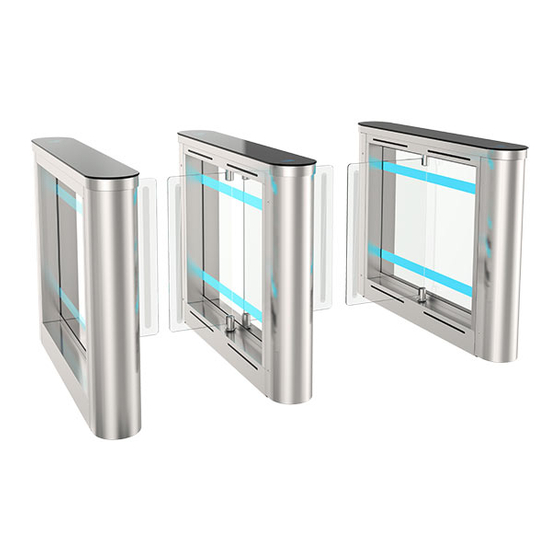
So, fulfillment of all requirements specified in this document is mandatory. The turnstile "Sweeper-G-BM" can be installed both singly and in line. The single turnstile includes two cabinets (left-hand and right-hand), one of which has one glass leaf in the form of swing leaf. -
Page 4: Warnings To The Customer On Safe Operation Of The Turnstile
WARNINGS TO THE CUSTOMER ON SAFE OPERATION OF THE TURNSTILE These warnings are designed for ensuring of safety during operation of the turnstile to prevent violation of safety characteristics by improper installation or operation. These warnings are aimed at drawing attention of the customer to safety problems. -
Page 5: Description And Operation
Height (H) glass top lid lane (W) 1010 1318 Sweeper-G-BM-1 500 When the turnstile with more than two lanes is ordered: = 708 · s + b total where s – number of 500 mm lanes; b - lid width -208 mm;... - Page 6 Height (H) lane (W) inserts 1010 1310 Sweeper-G-BM-1 500 When the turnstile with more than two lanes is ordered: = 700 · s + b total where s – number of 500 mm lanes; b - lid width - 200 mm;...
- Page 7 Overall dimensions of cabinet without leaves - Table 3 Max. Dimensions, mm Description of the Order code weight, turnstile component Height Width Length One side cabinet Master SWEEPER-G-BM-1.1 Т3.КСD.XD 1310 One side cabinet Slave SWEEPER-G-BM-1.2 1010 (208*) (1318*) Double side cabinet Master/Slave Sweeper-G-BM-2 Т3.КСD.XD.X Solid glass top lid Stainless steel top with glass inserts Fig.
-
Page 8: Specifications
1.3.1 The turnstile modification depends on the number of solid lanes: 1) For arrangement of single access way the turnstile "Sweeper-G-BM-1" is a set of two similar in design cabinets (Master - with one swing glass leaf and Slave - without one swing glass leaf) (reference designation Т3.КСD.ХD);... -
Page 9: Design And Operation
The turnstile is one or more auxiliary cabinets "Sweeper-G-BM-2" (Master/Slave) with one swing glass leaves (See Fig. 5). The number of auxiliary cabinets to be specified in the order. The turnstile "Sweeper-G-BM-2" is used within group of the turnstile "Sweeper-G-BM-1". - Page 10 90° to either side depending on access direction. Each leaf is actuated by separate gear motor 13. Additional double sided cabinet "Sweeper-G-BM-2" is equipped with one gear motors 13. In case of 230V power supply failure the turnstile leaves will be released and will remain in the position in which they were.
- Page 11 12 – main controller АUIA.206.21.20.00; 13 – link board for Master and Slave; 14 - circuit breaker; Fig. 7 – General appearance and design of “Sweeper-G-BM-1” turnstile mechanism (Master cabinet) 1.4.3 Principle of operation 1) Turnstile status indication - LED lighting display showing access status;...
- Page 12 2) Access cycle: Standby mode 1. In the initial state the turnstile glass leaves are located perpendicular to the body blocking the access. 2. The turnstile is opened for access in the direction "А" or "В" after the appropriate command from ACS or control panel is issued. 3.
-
Page 13: Description And Operation Of Controlers As Integral Components Of The Turnstile
1.5 Description and operation of controlers as integral components of the turnstile 1.5.1 Turnstile controller AUIA.206.21.20.00 1.5.1.1 Appearance of controller AUIA.206.21.20.00 is shown in Figure 10. 1.5.1.2 Description of operation The controller provides algorithm of operation of the whole turnstile. It is assembled on the card from foil-clad textile laminate of 120 х... - Page 14 1 - ON - when command is generated the turnstile will be opened for 5 seconds; OFF - when command is generated the turnstile will be opened for the time set by ACS; 2 - ON- the state of outputs OUT1-5 will be NC; - OFF - the state of outputs OUT1-5 will be NO;...
- Page 15 Table 6 Connector/ Signal parameters and Designation Direction Purpose Contact No description 1) logical «0» (0 2,2) V; INP1 ХТ4/1 ENTRY "TO BE OPENED FOR 2) logical «1» (3 5) V; ("TO BE OPENED A") SINGLE/FREE ACCESS" INP2 3) active level of signal ХТ4/2 ENTRY...
-
Page 16: Motor Controller Аuia.401.00.00-01
1.5.2 Motor controller АUIA.401.00.00-01 1.5.2.1. Description of motor controller АUIA.401.00.00-01 The controller АUIA.401.00.00-01 is designed to control BMDrive ® gear motors, which drives the turnstile leaves in motion. At each passage of turnstile installed one of controller АUIA.401.00.00-01: the controller drive the leaf in the Master cabinet. - Page 17 1.5.2.2. Description of the main page of the controller An OLED display and 4 control buttons are installed on the front side of the AUIA.401.00.00-01 controller for the displaying the current state of the controller and for configuration settings at menu After initialization of the controller the main page of the menu is displayed on the screen.
- Page 18 № Direction Description Designation Connector/contact XT1/1 EXIT Common wire of the control panel (GND ) XT1/2 DATA RS485 (1) communication line with 7-button TISO control XT1/3 DATA panel XT1/4 EXIT Power output for control panel (+12V) EXIT XT1/5 +12V Power output (+12V) for additional devices...
- Page 19 Continued table 7 XP6/1 RS - A DATA RS 485 (2) communication line with the leaf position sensor XP6/2 RS - B DATA Сommon XP6/3 EXIT XP6/4 +12V EXIT Power supply of leaf position sensor XP8/1 ENTRY Jumper of line RS 485 (2) pull up resistor XP8/2 ENTRY Jumper of line RS 485 (2) termination resistor (load)
-
Page 20: Intended Use
2 INTENDED USE 2.1 Operation restrictions 2.1.1 The turnstile must be used in the environment specified in p. 1.1.5 of this document subject to the specifications listed in section 1.2. 2.1.2 It is forbidden to use the turnstile: – at the presence of mechanical rattle in movable parts of the turnstile; –... - Page 21 2.2.5. Total configuration of the "Sweeper-G-BM" turnstile lanes Fig. 16 – The "Sweeper-G-BM" turnstile lanes arrangement options WARNING: The damages occurred during the turnstile transportation are not covered by the manufacturer's warranty liabilities...
- Page 22 2.2.6. Installation procedure. The turnstile installation procedure is as follows: Damages to be fixed (picture to be taken, damage report to be made). The turnstiled to be unpacked and inspected for defects and damages as well as completeness to be checked according to the turnstile data sheet;...
- Page 23 The relative position of cabinets and vertical position of the turnstile to be respected. Fig. 18 – Installation dimensions of the "Sweeper-G-BM-1" and "Sweeper-G-BM-2" turnstiles set The relevant holes to be drilled on the surface according to the marking due to diameter of anchors (12×120М10) for the turnstile fixation included in the scope of delivery.
- Page 24 Fig. 19 – General view of connection between cabinets...
- Page 25 Option 1 Option 2 Fig. 20 – Options of cable connection between cabinets Master and Slave...
- Page 26 7.- The glass leaves to be installed on the glass holder shaft and adjust the zero position of the leaves(see further par.4.3) Fig. 21 - General view of the "Sweeper-G-BM-1" turnstile cabinet installation 12) Turnstile connection: a) Power supply cable ~230 V to be connected (Fig. 22): - Phase L to be connected to circuit breaker;...
- Page 27 13) Installation of proximity card reader∗ upon availability of access control system (ACS) - The turnstile lid b (or glass top) to be removed by unscrewing screws а from frame (Fig.24); - Screws to be unscrewed and acrylite to be removed; - The maximum height of the card reader to be installed is 25 mm with specified permissible dimensions 110х80 - Acrylate to be fixed with screws in the previous position;...
-
Page 28: Turnstile Preparation For Use
2.3 Turnstile preparation for use 2.3.1 Commissioning guidelines Prior to the turnstile energization: 1) make sure of proper connection and good condition of all connecting cables; 2) clear the turnstile leaf swing area from foreign particles. When mains cable of power supply unit is connected to the network the turnstile operating mechanism is energized: leaves are locked from swinging in both directions barring access. -
Page 29: Contingency Actions
Continued Table 8 "LOCK" button to be Make sure that swing 9. Locked access in pushed to lock access in Red LED of locked access in one leaf are locked one direction chosen direction ("A" or chosen direction is lit "B")* Both "LOCK"... -
Page 30: Maintenance Procedure
3.3 Maintenance procedure 3.3.1 The turnstile maintenance includes preventive measures which are taken according to the established frequency to maintain the turnstile in operational condition, decreasing of component wearing and prevention of faults and malfunctions. 3.3.2 Daily and periodic maintenance of the turnstile are recommended. Normally the daily maintenance is carried out before the beginning of operation or during operational timeout and includes visual inspection of the turnstile's housing and, if required, troubleshooting of mechanical damages, surface corrosion and contamination. -
Page 31: Routine Maintenance
4 ROUTINE MAINTENANCE 4.1 General guidelines Minor malfunctions of the turnstile are listed in Table 10 and to be remedied by the customer. More complicated malfunctions to be remedied by the manufacturer’s representative. IMPORTANT: INSPECTION, CLEANING, REPAIR OF THE TURNSTILE COMPONENTS TO BE PERFORMED ONLY AFTER THE TURNSTILE DEENERGIZATION! 4.2 Possible malfunctions Possible malfunctions of the turnstile and their remedies are listed in Table 10... -
Page 32: Adjustment Of The Zero Position Of Leaf For "Sweeper-G-Bm-1
4.3. Adjustment of the zero position of leaf for “Sweeper-G-BM-1” For “Sweeper –G-BM” turnstiles, the zero position can be at point CLOSE (0). For turnstiles of this type, the zero position is set manually by the user during working area searching. -
Page 33: Transportation And Storage
Option ІІ (with АUIA.401.00.00-01 fig.26) Run the menu holding for 2 seconds the lower button (1) on the controller АUIA.401.00.00-01 choose “Calibration”->”GateZeroSet” controller. request calibration procedure, the turnstile will go to “OFF” mode. Set the zero point of leaves of Master cabinet manually (CLOSE position (3)) ... -
Page 34: Annex А.overall And Installation Dimensions Of The "Sweeper-G-Bm-1" And "Sweeper-G-Bm-2" Type Turnstile With Solid Glass Top Lid
Annex А.Overall and installation dimensions of the “Sweeper-G-BM-1” and “Sweeper-G-BM-2” type turnstile with solid glass top lid... -
Page 35: Annex В.overall And Installation Dimensions Of The "Sweeper-G-Bm-1" And "Sweeper-G-Bm-2" Type Turnstile With Stainless Steel Top With Glass Inserts
Annex В.Overall and installation dimensions of the “Sweeper-G-BM-1” and “Sweeper-G-BM-2” type turnstile with stainless steel top with glass inserts... -
Page 36: Annex С. Control Desk And Connection Diagram
Annex С. Control desk and connection diagram 1 – control panel body; 5 – "FREE ACCESS" mode control button 2 – "SINGLE ACCESS" mode control button 6 – "PANIC" mode control button 3 – front plate; 7 – access direction LED display; 4 –... -
Page 37: Continued Annex С. Control Panel And Connection Diagram
Continued Annex С. Control panel and connection diagram Fig. B.2 – Connection diagram of control panel AUIA.114.02.00.00... -
Page 38: Annex D.1. Wiring Diagram Of The Sweeper-G-Bm 1.1 Bldc Master (Auia.206-06.1) Rev 0.7
Annex D.1. Wiring diagram of the Sweeper-G-BM 1.1 BLDC Master (AUIA.206-06.1) Rev 0.7 MINI-FIT 8 Z5BLD120-24GUL ПВ3 0.75 (Green) MOT B (V) BL 1 BL 2 BL 3 BL 4 BL 5 BL 6 Hall C (W) ПВ3 0.75 (Yellow ) MOT A (U) ПВ3 0.75 (Blue) -
Page 39: Annex D.2.Wiring Diagram Of The Sweeper-G-Bm 1.2 Bldc Slave (Auia 206-07.12) Rev 0.7
Annex D.2.Wiring diagram of the Sweeper-G-BM 1.2 BLDC Slave (AUIA 206-07.12) Rev 0.7 PCB.205.01.05.00 XS25 +12V PCB 715.001 IROUT 1 IROUT 2 IROUT 3 OUT1 X T3 59-6 IROUT 4 OUT2 58-6 58-7 IROUT 5 OUT3 60-1 IROUT 6 485_A... -
Page 40: Annex D.3 Wiring Diagram Of The Sweeper-G-Bm-2 Bldc Master/Slave (Auia 206-07.02) Rev 0.7
Annex D.3 Wiring diagram of the Sweeper-G-BM-2 BLDC Master/Slave (AUIA 206-07.02) Rev 0.7 AA 1 M INI-FIT 8 Z 5BLD120-24GUL ПВ3 0 .7 5 (Gre e n ) M OT B (V) Hall C (W) + 5V ПВ3 0 .7 5 (Ye l l o w ) M OT A (U) ПВ3 0 .7 5 (Bl u e ) -
Page 41: Annex E.1. Diagram Of The Turnstile Connection To Access Control System (Acs)
Annex E.1. Diagram of the turnstile connection to access control system (ACS) Relay 1 Relay 2 Door contact 1 Door contact 2 inp1 - "TO BE OPENED A" in pulse mode. When command is issued entry is activated for 5 sec. inp2- "TO BE OPENED B"... -
Page 42: Annex E.2. Diagram Of The Turnstile Connection To Access Control System (Acs)
Annex E.2. Diagram of the turnstile connection to access control system (ACS) inp1- " TO BE OPENED A" in pulse mode. When command is issued the input is activated for 5 sec. . inp - 2 " TO BE OPENED B" in pulse mode. When command is issued the input is activated for 5 seconds. -
Page 43: Annex E.3 Diagram Of The Turnstile Connection To Fire Alarm (Fa)
Annex E.3 Diagram of the turnstile connection to fire alarm (FA) inp1- " TO BE OPENED A" in pulse mode. When command is issued the input is activated for 5 sec. inp - 2 " TO BE OPENED B" in pulse mode. When command is issued the input is activated for 5 seconds. -
Page 44: Annex E.4 Diagram Of The Turnstile Connection To Control Panel
Annex E.4 Diagram of the turnstile connection to control panel 5 4 3 2 1... -
Page 45: Service Center
Manufacturer: LLC TiSO-PRODUCTION 14, Promyslova Street, Kyiv, 02088, Ukraine Phone: +38 (044) 291-21-11 Tel./fax: +38 (044) 291-21-02 E-mail: sales@tiso.global www.tiso.global SERVICE CENTER e-mail: service1@tiso.global Our equipment meets the requirements of European standards: EN ISO 12100:2010, EN ISO 14118:2018, EN 60204-1:2018,...
Need help?
Do you have a question about the SWEEPER-G-BM and is the answer not in the manual?
Questions and answers