
Related Manuals for Tiso ONYX-S


Summary of Contents for Tiso ONYX-S
- Page 1 "TiSO-PRODUCTION" LTD SERVO-DRIVEN TRIPOD TURNSTILES ONYX - S ONYX –M ONYX - XS OPERATION AND INSTALLATION MANUAL Combined, rev.1.2.3 2024 UKRAINE...
-
Page 2: Table Of Contents
6. DISPOSAL CONSIDERATIONS ........................29 Annex А.1. Overall and installation dimensions of the turnstile “ONYX-XS” ............30 Annex А.2. Overall and installation dimensions of the turnstile “ONYX-S” ............31 Annex А.3. Overall and installation dimensions of the turnstile “ONYX-M” ............32 Annex B. -
Page 3: Introduction
(3 barrier rods) Example of reference designation of the servo-operated turnstile with solid body of brushed stainless steel should be T3.ТСC.SE, according to ТU U 28.9-32421280-005:2018. Model Coding Description T3.TCC.SE ONYX-S T3.TCC.PE АUIA.150 T3.TCC.KE T3.TYK.SE ONYX-M T3.TYK.PE АUIA.151 T3.TYK.KE... -
Page 4: Customer Warnings On Safe Operation Of The Turnstile
Operation Manual CUSTOMER WARNINGS ON SAFE OPERATION OF THE TURNSTILE These warnings are designed to ensure safety during operation of the turnstile to prevent violation of safety features by improper installation or operation. These warnings are aimed at drawing attention of the customer to safety problems. -
Page 5: Description And Operation
1.1.2 The turnstile dimensions and weight correspond to the values specified in Table 1. Table 1 - The turnstile dimensions and weight Dimensions, mm Cabinet Designation of Max. Model size, modification weight*, kg (LхW), mm ONYX-S 1075 381х312 T3.TCC.XE T3.TYK.ХE ONYX-M 1005х290 1076 1005 ONYX-XS 381х324 Х... -
Page 6: Specifications
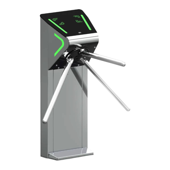
Operation Manual Continued Table 9 Explosion-proof, does not contain conductive dust, corrosive gases and Environment vapors in concentrations that destroy insulation and metals that disrupt the normal operation of the equipment installed in the turnstile in closed rooms in the absence of direct impact of atmospheric Place of installation precipitation and solar radiation vertical, not more than 1 °... - Page 7 Operation Manual The servo-operated waist-high turnstile design consists of the following major devices and components (See Figure 2): ONYX-S ONYX-M ONYX-XS 1 - turnstile rack; 6 – hub; 2 – RGB LED front status display; 7 – arm (barrier arm);...
-
Page 8: Design And Operation
Operation Manual 1.4 Design and operation 1.4.1 Actuating mechanism design Top view 1 - gear motor; Front view 2 - position sensor; 3 - antipanic device; 4 – locking solenoid; 5 – driving belt; 6 – hub shaft; 7 – mechanism body; 8 –... - Page 9 Operation Manual 1.4.2.2 In the initial state, when the turnstile is deenergized, barrier arms are locked from rotation and access is barred. 1.4.2.3 Green indicator in the intended direction (Fig. 6) is lit on LED display and barrier arms are unlocked when access permission command in the direction “A”...
-
Page 10: Instrumentation, Tools And Accessories
Operation Manual 1.5 Instrumentation, tools and accessories Special-purpose tools are not required for the turnstile installation (multi-purpose measurement instrumentation and installation tools are enough). (See Figure 9). puncher; concrete drills (according to diameter of anchors included in the turnstile scope of delivery); ... - Page 11 Operation Manual The controller operates according to the program entered into memory of microprocessor. The turnstile mechanism and LED display are controlled depending on commands coming from the controller PCB.112.21.20.01 rotor of position, rotation speed and based on the logic entered into program.
-
Page 12: Turnstile Controller Рсв.112.21.20.01
Operation Manual 1.6.2 Turnstile controller РСВ.112.21.20.01 1.6.2.1. Purpose of controller РСВ.112.21.20.01 The controller is designed for acquisition of control commands from peripherals (control panel, access control system etc.), generation of feedback signals, the turnstile LED display control and the motorized mechanism controller control. - Page 13 Operation Manual Table 7 - Application of jumpers № State State value Description CONTROLLER PCB 112.21.20.01 Tripod Turnstile type INP 1 INP 2 INP 3 OPTO 1 195 / 196 INP 4 OPTO 2 Mechanism type INP 5 OPTO 3 SGN 1 SGN 2 SGN 3...
- Page 14 Operation Manual 1.6.2.3. Description of operation The controller operates according to the program entered into microprocessor memory. The turnstile mechanism and LED displays are controlled according to control commands and status of rotor position sensors based on the logic downloaded into program. Control commands can be transmitted via RS485 (from control panel) or logical inputs (by closing and opening of inputs “INP1”...
- Page 15 Operation Manual AUTHORIZATION OF SINGLE ACCESS IN TWO DIRECTIONS Since the turnstile having one rotor can't rotate in two directions simultaneously, the controller can only unlock rotor in two directions and after access in one of directions is started, the reverse direction will be closed. The controller is switched to this mode if in the INITIAL STATUS it simultaneously acquires "TO BE OPENED A"...
- Page 16 Operation Manual Continued Table 9 OUT3 («DETECTION OF ХТ2/4 EXIT Signal is generated by controller ACCESS А ») 4) resistance of public key when rotor revolves from 64º to OUT4 («DETECTION OF (5÷7) Ohm; 120º in the relevant direction ХТ2/5 EXIT ACCESS B») 5) active level of signal...
-
Page 17: Intended Use
Operation Manual 2. INTENDED USE 2.1 Operational limitations 2.1.1 The product should be operated under the conditions specified in 1.1.4 of this document, while keeping the specifications given in section 1.2. FOLLOWING IS PROHIBITED: 1) TO USE THE TURNSTILE NOT FOR APPOINTMENT (see section 1 "DESCRIPTION AND WORK");... - Page 18 Operation Manual 2.2.2 General layout of the turnstile access ways Side view Top view Fig.12 – General layout of the turnstile access ways (conditionally) 2.2.3 Installation procedure The turnstile installation procedure is as follows: 1) The package integrity to be checked prior to unpacking. If package is damaged, then damages to be fixed (picture to be taken, damage report to be made).
- Page 19 Operation Manual а) ONYX-XS б) ONYX-S С) ONYX-M Fig.13– Tripod type turnstile installation marking...
- Page 20 Operation Manual 7) For access to fixing and technological openings of the base and terminal blocks of the ONYX-XS tripod turnstile (Fig. 14) is required: 1. Remove the top lid: loosen the screw at the turnstile housing using the hexagon. Then slide the glass lid by 1.5 cm to the side;...
- Page 21 Operation Manual 8) For access to fixing and technological openings of the base and terminal blocks of the ONYX-S tripod turnstile (Fig. 15) is required: 1. Remove the lock door by turning the lock key; 2. Remove the floor cover by unscrewing the two screws;...
- Page 22 Operation Manual 9) For access to technological openings of ONYX-M tripod turnstile base is required: 1. Remove two doors of the turnstile rack by unscrewing one screw fixed the door to the body. 2. Pull the required cables. 3. Secure with anchors. 4.
- Page 23 The cable outlet point to be aligned with the hole on the turnstile mounting plate (Fig.13) 9) Installation of hub on the tripod turnstile (Through the example of the turnstile Onyx-S). (For the sake of convenience installation of the hub with barrier arms is acceptable at the end of installation and connection of the turnstile): a) The hub (1) barrier arms (2) to be set out manually (See Fig.
- Page 24 Operation Manual 11) The following cables to be pulled to the turnstile installation site: Power supply cable 230 V ~; Control panel link cable; Access control system (ACS), if any, connection cables; The turnstile to be installed upright at the prepared location.
- Page 25 Operation Manual 2.2.4 Adjustment of the zero position of the hub with arms 1. On the electronic board PCB.730 of the magnetic sensor (Fig.19) press the button (1) and hold (make sure that the force on the button does not bend the board);...
-
Page 26: Preparation For Use
Operation Manual 2.3 Preparation for use 2.3.1 Commission guidelines Prior to the turnstile energization: 1) make sure of proper connection and good condition of all connecting cables; 2) the turnstile barrier arm turning area to be cleaned from foreign particles. When mains cable of power supply unit is connected to network the turnstile control mechanism are energized: barrier arms are locked from rotation in both directions barring access. -
Page 27: Contingency Actions
Operation Manual 2.4. Contingency actions For emergency evacuation of people (in case of fire, natural disasters, etc.) and to ensure free access, the turnstile to be released by sending the relevant command from control panel. To have fully open passage please use the anti- panic mechanism. -
Page 28: Current Repair
Operation Manual cards are used;- verification of reliability of the turnstile screw joints and earthing connections - to be tightened, if applicable;- lubrication of all rubbing stop levers, wheel and pinion teeth of the turnstile control mechanism at least monthly with lubricant OKB-122-7 according to GOST 18179-72 or LITOL 24, Ciatim or engine oil. Table 12 - Periodic maintenance by technical staff Component Period... -
Page 29: Checking The Product After Repair
Operation Manual Continued table 13 Have no a communication with the Check the wires The Indication does controller Check the LED indicator not work Damaged the wires Replace the faulty LED indicator The LED indicator is faulty The position sensor is set wrong The Adjust the position sensor Bars (arms) stay in position sensor is faulty... -
Page 30: Annex А.1. Overall And Installation Dimensions Of The Turnstile "Onyx-Xs
Annex А.1. Overall and installation dimensions of the turnstile “ONYX-XS”... -
Page 31: Annex А.2. Overall And Installation Dimensions Of The Turnstile "Onyx-S
Annex А.2. Overall and installation dimensions of the turnstile “ONYX-S”... -
Page 32: Annex А.3. Overall And Installation Dimensions Of The Turnstile "Onyx-M
Annex А.3. Overall and installation dimensions of the turnstile “ONYX-M” Ø14 4 holes... -
Page 33: Annex B. Control Panel And Connection Diagram
Annex B. Control panel and connection diagram 1 – control panel body; 5 – "FREE ACCESS" mode control button 2 – "SINGLE ACCESS" control button 6 – "PANIC" mode control button mode control button 3 – front plate; 7 – access direction LED display; 4 –... -
Page 34: Annex C. Servo-Operated Tripod Turnstile Wiring Diagram
Annex C. Servo-operated tripod turnstile wiring diagram... -
Page 35: Annex D.1 Wiring Diagram Of The Turnstile Connection To Access Control System (Acs) In Pulse Mode
Annex D.1 Wiring diagram of the turnstile connection to access control system (ACS) in pulse mode OPTO XT3.1 XT1.1 RESET OPTO1 Relay 1 Relay 2 XT2.1 Door contact 1 XT .1 Door contact 2 М + GB XT5.1 inp1 - "PANIC" inp2 - "TO BE OPENED A"... -
Page 36: Annex D.2. Wiring Diagram Of The Turnstile Connection To Access Control System (Acs) In Hold Mode
Annex D.2. Wiring diagram of the turnstile connection to access control system (ACS) in hold mode... -
Page 37: Annex D.3. Diagram Of The Turnstile Connection To Fire Alarm (Fa)
Annex D.3. Diagram of the turnstile connection to fire alarm (FA) OPTO XT3.1 XT1.1 RESET OPTO1 XT2.1 XT .1 М + GB XT5.1 inp1 - "PANIC" inp2 - "TO BE OPENED A" in pulse mode. When command is issued entry is activated for 5 sec. inp3 - "TO BE OPENED B"... -
Page 38: Annex D.4. Wiring Diagram Of The Turnstile Connection To Fire Alarm System (Fas)
Annex D.4. Wiring diagram of the turnstile connection to fire alarm system (FAS) OPTO XT3.1 XT1.1 RESET OPTO1 XT2.1 XT .1 М + GB XT5.1 OPTO XT3.1 XT1.1 RESET OPTO1 XT2.1 XT .1 М + GB XT5.1 Figure D.4 – Wiring diagram of the turnstile connection to fire alarm system (FAS) -
Page 39: Annex D.5. Wiring Diagram Of The Turnstile Connection To Control Panel
Annex D.5. Wiring diagram of the turnstile connection to control panel OPTO XT1.1 XT3.1 RESET OPTO1 XT2.1 XT .1 М + GB XT5.1... - Page 40 Manufacturer: LLC TiSO-PRODUCTION 14, Promyslova Street, Kyiv, 02088, Ukraine Phone: +38 (044) 291-21-11 Tel./fax: +38 (044) 291-21-02 E-mail: sales@tiso.global www.tiso.global SERVICE CENTER e-mail: service1@tiso.global Our equipment meets the requirements of European standards: EN ISO 12100:2010, EN ISO 14118:2018, EN 60204-1:2018,...
Need help?
Do you have a question about the ONYX-S and is the answer not in the manual?
Questions and answers