
Related Manuals for Tiso GATE-GS SLIM T3.KCC.SD Series


Summary of Contents for Tiso GATE-GS SLIM T3.KCC.SD Series
- Page 1 “TiSO-PRODUCTION” LTD WAIST-HIGH TURNSTILE SERVO-OPERATED SWING GATE GATE-GS SLIM Т3.KСC.SD OPERATION MANUAL AUIA.208-02 (rev.1.1.2) UKRAINE 2023...
-
Page 2: Table Of Contents
Operation Manual Rev.1.1 CONTENTS INTRODUCTION ................................3 WARNINGS TO THE CUSTOMER ON SAFE OPERATION OF THE TURNSTILE ........... 4 1. DESCRIPTION AND OPERATION ..........................5 1.1 General Information and Purpose ..........................5 1.2 Specifications ................................6 1.3 Product components and scope of delivery ....................... 6 1.4 Design and operation .............................. -
Page 3: Introduction
Operation Manual Rev.1.1 INTRODUCTION This Operation Manual (hereinafter referred to as OM) covers the servo-operated waist-high turnstile of swing gate type (hereinafter referred to as the "turnstile"). The Operation Manual contains information about design, specifications, installation for proper operation and maintenance of the turnstile. This Operation Manual is prepared in compliance with the specification requirements of ТU U 28.9-32421280- 005:2018. -
Page 4: Warnings To The Customer On Safe Operation Of The Turnstile
Operation Manual Rev.1.1 WARNINGS TO THE CUSTOMER ON SAFE OPERATION OF THE TURNSTILE These warnings are designed for ensuring of safety during operation of the turnstile to prevent violation of safety characteristics by improper installation or operation. These warnings are aimed at drawing attention of the customer to safety problems. -
Page 5: Description And Operation
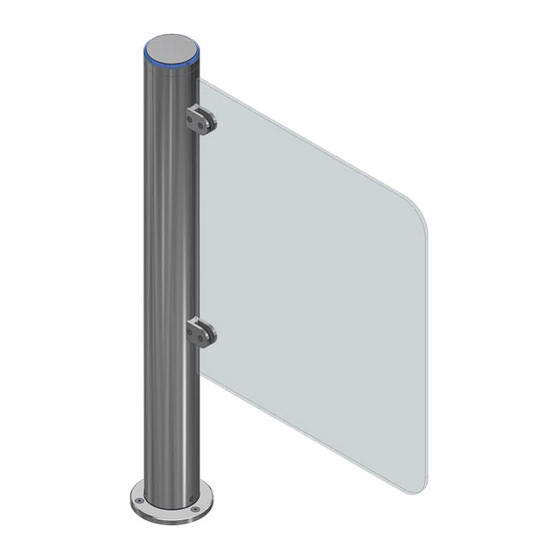
Operation Manual Rev.1.1 1. DESCRIPTION AND OPERATION 1.1 General Information and Purpose 1.1.1 Purpose Gate-GS Slim - is an automatic swing gate with a glass leaf. The ultra-thin body highlights its elegant look. Along with standard dimensions, width and height of glass leaf can be enlarged according to project requirements for the passage of wheelchairs and transportation of oversize goods. -
Page 6: Specifications
Operation Manual Rev.1.1 1.1.3 The operation condition parameters according to GOST 15150-69 for climatic modification NF4 are specified in Table 2. Table 2 The parameters for climate version NF4 (for indoor application) Operational conditions from + 1 to + 40 °С Ambient temperature 80 % if plus 25 ºС... -
Page 7: Design And Operation
Operation Manual Rev.1.1 1.3.2 Scope of Delivery Turnstile is delivered by one packing place. 1. Servo-Drive Swing Gate “GATE-GS SLIM” - 1 pc 2. Glass leaf - 1 pc 3. Control panel AUIA.111.22.00.00 - 1 pc 4. Anchor Redibolt (12×100 М10) - 3 pcs 5. -
Page 8: Instrumentation, Tools And Accessories
Operation Manual Rev.1.1 1.4.2 Principle of operation Standby Operating modes of the turnstile: 1) open in the direction "A" or "B"; 2) free access in the direction "A" or "B". The operating status of the gate in both directions is displayed in the turnstile housing top lid by means of built-in LED lighting indication. -
Page 9: Description And Operation Of Controllers As A Component Of The Turnstile
Operation Manual Rev.1.1 1.6 Description and operation of controllers as a component of the turnstile 1.6.1 Purpose of the turnstile leaf mechanism controller РСВ.201.01.00.00 The controller is designed for acquisition of commands from the turnstile controller PCB.112.21.20.01 and generation of the motorized mechanism motor control signals. 1.6.1.1 The Controller is assembled on the (85х70)mm card, on which electronic components and connectors for external connections are installed. - Page 10 Operation Manual Rev.1.1 Table 6 Connec tor / Signal parameters and Designati Direction Purpose Contact description Command “ TO BE OPENED IN THE DIRECTION А” (with 4 X1/1 ENTRY sec. closing delay) Command “ TO BE OPENED IN THE DIRECTION B” (with 4 1) logical «0»...
-
Page 11: Intended Use
Operation Manual Rev.1.1 swing gate leaf. Sensor signals come to inputs «IN5», «IN6», «IN8» (X1/5, X1/6, X1/8). Rotation speed signal from the relevant sensor come to the controller input «IN7» (X1/7). Besides motor current is constantly measured and is limited, if necessary. After leaf reaches the definite angle, the controller switches motor to braking mode to prevent impact of leaf about rotation limiter. - Page 12 Operation Manual Rev.1.1 Connection of all cables to be performed only when power supply is OFF; Cables to be laid in compliance with electric code; The turnstile to be installed by at least 2 installers. 2.2.4 Installation procedure The turnstile installation procedure is as follows: 1) The package integrity to be checked prior to unpacking.
- Page 13 Operation Manual Rev.1.1 Cables to be pulled through available access holes in the turnstile base plate 10 (See Fig.7). Fixation holes at the turnstile base plate 10 to be aligned with prepared surface holes The turnstile to be fixed by means of anchors included in the scope of delivery 11 (М8х120, 3 pcs.).
- Page 14 Operation Manual Rev.1.1 12) Turnstile connection: а) Power supply cable ~220 V to be connected (Fig.9a): - Phase L to be connected to the circuit breaker; - Neutral (N) to be connected to terminal ~220V (N); - Earth (PE) to be connected to earthing terminal (РЕ).
- Page 15 Operation Manual Rev.1.1 Fig. 11 – Turnstile leaf in zero position Fig. 12 – Signals for changing rotation angle on РСВ.201.01.00.00 controller Fig. 13 – Magnetic sensor board PCB 730.003...
-
Page 16: Preparation For Use
Operation Manual Rev.1.1 2.3 Preparation for use 2.3.1 Commission guidelines Prior to the turnstile energization 1) make sure of proper connection and good condition of all connecting cables; 2) clear the turnstile’s leaf turning area from foreign particles. Rotation of leaf is locked when mains cable of power supply unit is connected to the network. The turnstile is put in initial state access is blocked by leaf. -
Page 17: Current Repair
Operation Manual Rev.1.1 Normally the daily maintenance is carried out before the beginning of operation or during operational timeout and includes visual inspection of the turnstile's housing and, if required, troubleshooting of mechanical damages, surface corrosion and contamination. The means recommended for cleaning stainless steel products are given in Table 8. Table 8 Name of means Manufacturer Company... -
Page 18: Postrepair Checkout
Operation Manual Rev.1.1 Continuation table 10 Disruption of connection of control panel Connection of control panel with 5. Turnstile does not respond to with turnstile turnstile to be restored control panel commands Control panel is out of order Control panel to be replaced Absence of power supply +12V Power supply unit to be checked Controller РСВ.201.01.00.00 is out of order... -
Page 19: Annex А. Overall And Installation Dimensions Of "Gate-Gs Slim" Type Turnstile
Annex А. Overall and installation dimensions of “Gate-GS Slim” type turnstile Ø101 Ø101 Ø150 Ø150 Mounting base Ø150 Ø128 Ø40 Cable input Ø13 3 holes... -
Page 20: Annex B. Control Panel And Connection Diagram
Annex B. Control panel and connection diagram 1 – control panel housing; 2 – front face; 3, 5 – access direction LED displays; 4 – "SINGLE ACCESS" mode control button; 6 – "FREE ACCESS" mode switch; 7 – controller connection terminals Figure B.1 –... -
Page 21: Annex В. Wiring Diagram Of The Swing Gate Type Turnstile "Gate -Gs Slim
Annex В. Wiring diagram of the Swing Gate type turnstile «Gate –GS Slim» TOP INDICATION XT 4 (HU4) +12V LED R +12v LED G LED B ALARM OUT XT 5 (HU5) ALARM SET ZERO 730 3 +12V SPEED ANGLE 1 ANGLE 2 ZERO 3 SET ZERO IN... -
Page 22: Annex D. Wiring Diagram Of Turnstile Connection To Control Panel
Annex D. Wiring diagram of turnstile connection to control panel Gate GS SLIM X1 Control OPEN A OPEN B Gate SLIM PILLAR PILLAR INDICATION R PILLAR INDICATION G X1 Indication PILLAR INDICATION B PILLAR INDICATION R PILLAR 12V DC PILLAR INDICATION G Wiegant DATA 0 PILLAR INDICATION B Wiegant DATA 1... - Page 23 Manufacturer: LLC TiSO-PRODUCTION 14, Promyslova Street, Kyiv, 02088, Ukraine Phone: +38 (044) 291-21-11 Tel./fax: +38 (044) 291-21-02 E-mail: sales@tiso.global www.tiso.global SERVICE CENTER e-mail: service1@tiso.global Our equipment meets the requirements of European standards: EN ISO 12100:2010, EN ISO 14118:2018, EN 60204-1:2018, EN ISO...
Need help?
Do you have a question about the GATE-GS SLIM T3.KCC.SD Series and is the answer not in the manual?
Questions and answers