Table of Contents
Advertisement
Quick Links
Installation - Operation
Shot Controller
For use with non-flammable polyurethane foams. Not for use in explosive atmospheres.
2000 psi (13.8 MPa, 138 bar) Maximum Working Pressure
Important Safety Instructions
Read all warnings and instructions in this man-
ual and hydraulic proportioner manual
312062. Save these instructions.
See page 2 for model information.
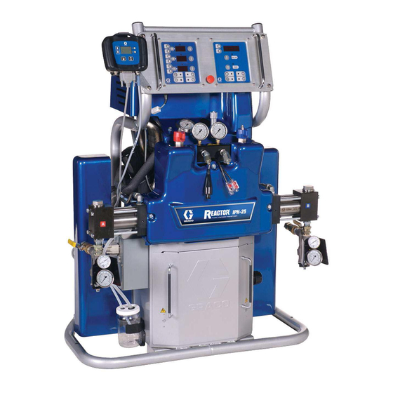
Proportioner shown includes Shot Controller, pro-
portioner also available without Shot Controller
312878E rev.c
ti11756a
Advertisement
Table of Contents

Related Manuals for Graco IPH-25 Series


Summary of Contents for Graco IPH-25 Series
- Page 1 Installation - Operation Shot Controller 312878E rev.c For use with non-flammable polyurethane foams. Not for use in explosive atmospheres. 2000 psi (13.8 MPa, 138 bar) Maximum Working Pressure Important Safety Instructions Read all warnings and instructions in this man- ual and hydraulic proportioner manual Proportioner shown includes Shot Controller, pro- 312062.
-
Page 2: Table Of Contents
Graco Standard Warranty ....36 312068 Proportioning Pump Repair-Parts Manual Graco Information ......36 Models IPH-25 SERIES... -
Page 3: Warnings
• Ground equipment, personnel, object being sprayed, and conductive objects in work area. See Grounding instructions. • Use only Graco grounded hoses. • Check gun resistance daily. • If there is static sparking or you feel a shock, stop operation immediately. Do not use equipment until you identify and correct the problem. - Page 4 Warnings WARNING ELECTRIC SHOCK HAZARD Improper grounding, setup, or usage of the system can cause electric shock. • Turn off and disconnect power at main switch before disconnecting any cables and before servicing equipment. • Connect only to grounded power source. •...
-
Page 5: Isocyanate Hazard
Isocyanate Hazard Isocyanate Hazard • Keep the ISO lube pump reservoir (if installed) filled with Graco Throat Seal Liquid (TSL), Part 206995. The lubricant creates a barrier between the ISO and the atmosphere. • Use moisture-proof hoses specifically designed for Spraying materials containing isocyanates creates ISO, such as those supplied with your system. -
Page 6: Component Identification
Component Identification Component Identification IPH System ti11820a Model 255811 shown . 1: IPH System with Front Cover Removed Key: Hydraulic Proportioner Shot Controller, HMI, and Bracket Electrical Enclosure Linear Sensor Assembly... - Page 7 Component Identification Human Machine Interface (HMI) Key: AA Up arrow key AE Bottom soft key AB Down arrow key AF Initiate shot button AC Mode select button AG LCD screen AD Top soft key Initiate Shot button Pressing this button will start a shot for either the selected shot number, the next shot number in the selected sequence, or when in manual mode will dis- pense until the user releases the button.
- Page 8 Component Identification Icons Icon Function Shown on Screen(s) General Icons Confirm changes • Exit without saving changes • • Setup screen #1 • Next Setup screen #3 • Run screen when Learn Mode is enabled • Setup screen #1 Previous •...
- Page 9 Component Identification Icon Function Shown on Screen(s) Disable Run Screen Shot Editing • Setup screen #7 Enter Learn Mode • Setup screen #8 Exit Learn Mode • Setup screen #8...
- Page 10 Component Identification Run Screen When no errors are active, “E” will be displayed. Shown only during shot dispensing in Shot or Sequence mode Displayed only in Sequence mode Key: BA Current operating mode BB n shot in sequence BC Number of shots executed for selected shot number BD Quantity of selected shot (Shot or Sequence modes) or previous shot (Manual mode) BE Quantity unit of measure (cubic centimeters or grams)
- Page 11 Component Identification Press up arrow key to access Setup Screen 8 Enter and confirm correct password Press up Press down arrow key arrow key This screen is skipped Press and hold bottom when password is disabled soft key for 2 sec Press down Press up arrow key...
-
Page 12: Conversion Kit Installation
Conversion Kit Installation Conversion Kit Installation The IPH-25 and IPH-40 systems include a hydrau- lic proportioner and conversion kit 24A024 and are assembled at the factory. These instructions are for installing Conversion Kit 24A024 onto an existing H-25 or H-40 hydraulic proportioner. - Page 13 Conversion Kit Installation Install Linear Sensor ti11759a 5. Place the magnet bracket plate (9) on the left side of the activator plate (21). 6. Pass two socket head cap screws (10) through the bottom two holes of magnet bracket plate (9) and activator plate (21).
- Page 14 Conversion Kit Installation Install Electrical Enclosure ti11757a Key: DA Screw DB Electrical enclosure cover DC Electrical enclosure DD Wire access cover screws DE Electrical cabinet 18. Remove three screws (DD) holding wire access 23. Install electrical enclosure cover (DB) to electrical cover to the electrical cabinet.
- Page 15 Conversion Kit Installation Install Shot Controller 29. Connect the “pump” plug to J12 on the motor control board. 30. Connect the “temp” plug to the “data” connector on the temperature control board. 31. Connect wire harness to the linear sensor. 32.
- Page 16 Conversion Kit Installation Simplified Schematic, Shot Controller Wiring See F . 18 on page 32 for detailed view. Key: FA Shot Controller FF Hydraulic Proportioner Motor Control FB Hydraulic Proportioner Fan Fuse Block Board FC Electrical Enclosure FG Shot Controller Power Cable FD Hydraulic Proportioner Temperature FH Port for Optional Data Reporting Kit Control Board...
- Page 17 Conversion Kit Installation Simplified Schematic, Shot Controller Electrical ti12349a...
- Page 18 Conversion Kit Installation Simplified Schematic, Alternate Gun Connection ti12350a...
-
Page 19: Setup
Setup Setup Hydraulic Proportioner Setup Setup Screen #2: Shot Number Definitions See hydraulic proportioner manual 312062. Controller Setup When in any of the setup screens, pouring is dis- abled. The shot quantity units, cubic centimeters or grams, for which each shot number quantity is defined is dependent on whether the material specific gravity To enter the setup screens, press and hold the top soft key for three seconds. - Page 20 Setup Setup Screen #4: Adjusting E52 Error Delay “Tap” and “Hold” Gun Modes “Tap” mode and “Hold” mode define how the machine responds to pulling/releasing the gun trigger and, if enabled, pressing/releasing the “Initiate Shot” button on the HMI. When in manual mode, the machine will only shoot when the gun trigger or “Initiate Shot”...
- Page 21 Setup Setup Screen #7: Enable/Disable Run To access the setup screens when the password is enabled, press the top soft key for three second and the Screen Shot Editing or “Initiate Shot” password entry screen will appear. Enter the password button and confirm to access the setup screens.
- Page 22 Setup Learn Mode Obtain Piston Range Information To view the physical piston movement, remove the front cover (CA) from the machine. Replace the cover when finished using Learn mode. Learn mode will need to be used following the installation of the conversion kit, the linear sensor 5.
- Page 23 AR Pour Gun, see manual 312888 available at www.graco.com. 1. Remove then re-supply power to the shot controller. 2. Within 20 seconds of the Idle Run Screen appear- ing, press and hold both the top soft key and the down arrow key for six seconds.
- Page 24 Setup Optional External Machine Control Key: GA Pin #1: External Machine Return Ground GB Pin #2: Not used GC Pin #3: Not used GD Pin #4: Not Used GE Pin #5: Ground for Cable Shields GF Pin #6: Not used GG Pin #7: Shot Number or Sequence n Shot Selection GH Pin #8: Dispense Request...
- Page 25 Setup Dispense Request Line After Pin #7 has been grounded n+1 times, there must be a delay of four times the period Pin #7 was grounded for each of the n+1 repetitions. For example, if Pin #7 See F . 15 on page 26. was grounded for 15 milliseconds then ungrounded for 15 milliseconds and so on, there must be a delay of 60 The gun must be configured to “Tap”...
- Page 26 Setup Pin #7: Shot Number or Sequence n Shot Request Not Grounded Grounded 15 mS 15 mS 15 mS 15 mS 15 mS 15 mS 15 mS 50 mS 4 X 15 mS 100 mS Pin #8: Dispense Request Not Grounded Grounded Dispensing begins Pin #9: Ready Status...
-
Page 27: Operation
Operation Operation Change Shot Volume/Weight The AR Pour Gun and shot controller modify the hydraulic proportioner to pour instead of spray but To change the defined shot volume or weight for the all operation procedures from hydraulic proportioner selected shot, first enter Run Screen Shot Editing mode operation manual 312062 are applicable. - Page 28 Operation Dispense Material Demo Mode Demo mode is an alternate operating mode that is iden- tical to standard operation but with a few exceptions. When in Demo mode, pouring, control of the gun and hydraulic proportioner, and Learn mode are all disabled. Also, settings and passwords saved in Demo mode are A shot can be initiated using either the gun trigger or the separate from settings saved in normal operation.
-
Page 29: Pressure Relief Procedure
Pressure Relief Procedure Pressure Relief Procedure 4. Turn PRESSURE RELIEF/SPRAY valves (SA, SB) to PRESSURE RELIEF/CIRCULATION . Route fluid to waste containers or supply tanks. Ensure 1. Relieve pressure in gun and perform gun shutdown gauges drop to 0. procedure. See gun manual 312888. 2. - Page 30 Pressure Relief Procedure...
-
Page 31: Troubleshooting
Troubleshooting Troubleshooting Key: Error Code Error Icon . 17: Error Alert Screen Error Codes Error Code Error Icon Cause Possible Solutions A key has been pressed for more than 30 • Check shot controller for stuck key • seconds Replace shot controller Linear sensor fault, often caused if in Learn •... -
Page 32: Parts
Parts Parts Model, Series Hydraulic Proportioner Conversion Kit 255811, A 253725 24A024 255812, A 253726 24A024 255813, A 253727 24A024 255814, A 255400 24A024 255815, A 255401 24A024 255816, A 255402 24A024 Hydraulic Proportioner Refer to hydraulic proportioner repair manual 312063 for parts lists for each hydraulic proportioner. - Page 33 Parts Part Description 255817 PENDANT, shot meter 256217 KIT, bracket, pendant 256230 ENCLOSURE, electrical, assy 287839 SENSOR, assembly 5◆ KIT, holder, magnet 6◆ BRACKET, mounting, linear sensor 7◆ BRACKET, mounting, magnet 8◆ SPACER, bracket, magnet 9◆ PLATE, clamp, bracket, magnet 10◆...
-
Page 34: Technical Data
Technical Data Technical Data Category Data Maximum Fluid Working Pressure Models IPH-25 and IPH-40: 2000 psi (13.8 MPa, 138 bar) Fluid:Oil Pressure Ratio Model IPH-25: 1.91:1 Model IPH-40: 1.64:1 Fluid Inlets Component A (ISO): 1/2 npt(f), 250 psi (1.75 MPa, 17.5 bar) maximum Component B (RES): 3/4 npt(f), 250 psi (1.75 MPa, 17.5 bar) maximum Fluid Outlets Component A (ISO): #8 JIC (3/4-16 unf), with #5 JIC adapter... -
Page 35: Performance Charts
Performance Charts Performance Charts AR Pour Gun Impingers and Reactor Foam Performance Chart 2000 (13.8, 138) A = IPH-25 at 50 Hz B = IPH-25 at 60 Hz C = IPH-40 at 50 Hz 1500 ❄D = IPH-40 at 60 Hz (10.3, 103) E = AR-C 23-B-1 impingers F = AR-C 36-C-1 Impingers... -
Page 36: Graco Standard Warranty
With the exception of any special, extended, or limited warranty published by Graco, Graco will, for a period of twelve months from the date of sale, repair or replace any part of the equipment determined by Graco to be defective.
Need help?
Do you have a question about the IPH-25 Series and is the answer not in the manual?
Questions and answers