Table of Contents
Advertisement
Quick Links
Installation and Operation
®
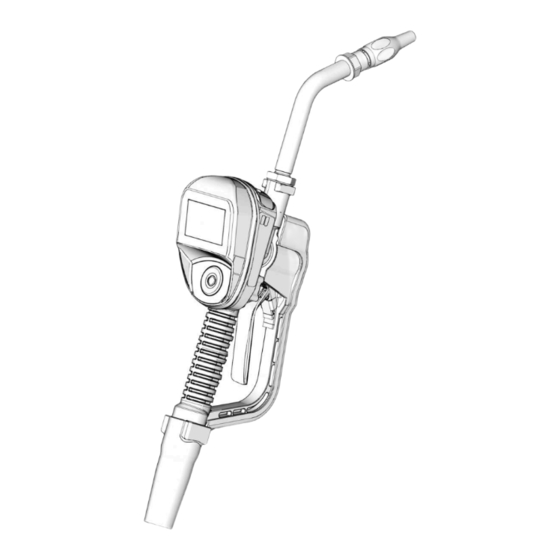
Pulse
Dispense Valve
For dispensing motor oil in conjunction with wireless communication with a Pulse Fluid
Management system. For professional use only.
Not approved for use in European explosive atmosphere locations.
Not approved for use in explosive atmospheres or hazardous (classified) locations.
See Models, page 4.
1500 psi (10 MPa, 103 bar) Maximum Working
Pressure
Important Safety
Instructions
Read all warnings and instructions in this
manual and in related Pulse System
manuals before using the equipment.
Save all instructions.
The metered dispense valve is designed to
dispense petroleum-based lubricants. Brake
cleaner and/or harsh solvents may damage the
plastic components.
Related Manuals
3A5410 - Pulse Pump Air Control (PAC)
3A5411 - Pulse Tank Level Monitor (TLM)
3A5414 - Pulse Hub
Contains Model XBee S2C Radio, IC:
1846A-XBS2C.
The metered dispense valve contains FCC ID MCQ-XBS2C. This device complies with Part 15
of the FCC Rules. Operation is subject to the following two conditions:
•
This device may not cause harmful interference.
•
This device must accept any interference received, including interference that may cause
undesired operation.
OIML Certificate R117/2019-A-NL1-20.01
https://www.oiml.org/en/oiml-cs/certificat_view
Metered
NOTICE
3A7397E
EN
Advertisement
Table of Contents

Subscribe to Our Youtube Channel
Related Manuals for Graco Pulse 26C935


Summary of Contents for Graco Pulse 26C935
- Page 1 Installation and Operation ® Pulse Metered 3A7397E Dispense Valve For dispensing motor oil in conjunction with wireless communication with a Pulse Fluid Management system. For professional use only. Not approved for use in European explosive atmosphere locations. Not approved for use in explosive atmospheres or hazardous (classified) locations. See Models, page 4.
-
Page 2: Table Of Contents
Contents Contents Models ........... . . 4 Warnings . - Page 3 Graco Information ........
-
Page 4: Models
Models Models Max Volumetric Flow Rate Model Swivel Extension Nozzle Fluid 26C935 1/2 NPT Rigid Automatic 26C936 1/2 NPT Flexible Automatic 3A7397E... -
Page 5: Warnings
Warnings Warnings The following warnings are for the setup, use, grounding, maintenance, and repair of this equipment. The exclamation point symbol alerts you to a general warning and the hazard symbols refer to procedure-specific risks. When these symbols appear in the body of this manual or on warning labels, refer back to these Warnings. - Page 6 Warnings WARNING FIRE AND EXPLOSION HAZARD When flammable fluids are present in the work area, such as gasoline and wind- shield wiper fluid, be aware that flammable fumes can ignite or explode. To help prevent fire and explosion: • Use equipment only in well-ventilated area. •...
-
Page 7: Metered Dispense Valve Overview
Metered Dispense Valve Overview Metered Dispense Header Information Valve Overview NOTE: The metered dispense valve’s operating parameters are controlled by the Pulse Fluid Management Software and set up by the System Administrator. The following information appears at the top of the Work Offline and Dispense screens. Metered Dispense Valve Name - Unique identification. -
Page 8: Sleep / Awake Mode
Metered Dispense Valve Overview Sleep / Awake Mode Open and Close the Nozzle • Sleep: Battery-saving mode. • Awake: Wakes up the metered dispense valve. Press any arrow button or ENTER on the metered dispense valve’s navigation pad. Open Lock and Unlock the Trigger Closed Unlocked •... -
Page 9: Typical Installation
The typical installation shown in F . 6 is only a guide. It is not a complete system design. Contact your Graco distributor for Mounting Bracket Kit 249440 is available to assistance in designing a system. mount the metered dispense valve on a console (F . -
Page 10: Installation
Installation Installation Pressure Relief Procedure Ground Follow the Pressure Relief Procedure whenever you see this symbol. The equipment must be grounded to reduce the risk of static sparking. Static sparking can cause fumes to ignite or This equipment stays pressurized until explode. -
Page 11: Pre-Installation Procedure
Installation Pre-Installation Procedure Flush Equipment The equipment was tested with lightweight oil, which is left in the fluid passages to protect parts. To avoid contaminating the fluid, flush the equipment with a compatible solvent before use. Follow Pressure Relief Procedure, page 10. -
Page 12: Install The Metered Dispense Valve
Installation Install the Metered Install the Extension Tube Dispense Valve Adjust the nut (c) on the extension (2) to ensure maximum thread engagement of the extension (F . 9). Follow Pressure Relief Procedure, page 10. Slide the swivel boot (a) back over the hose, the small end first, to access the swivel fitting (6) (F . -
Page 13: Install The Nozzle
Installation Install the Nozzle Thread the nozzle (3) onto extension (2) . 10). . 11 NOTICE • To prevent damaging the nozzle, only tighten the nozzle with a wrench on the flats of the nozzle bushing, as shown in F . -
Page 14: Set-Up
Set-Up Set-Up Main Menu Screen This screen provides access to the main metered dispense valve functions: • DISPENSE, page 20 • SET-UP, page 24 • UTILITY MENU, page 26 . 14 Press ENTER. REGISTERING appears in the middle of the display during registration (F . -
Page 15: Calibration
Set-Up If the metered dispense valve does not For best results, dispense a similar register with the Pulse Fluid volume to what the meter will be Management Software, FAILED measuring when in use. Performing appears on the display (F . 17). multiple calibration dispenses and calculations can be made for increasing NOTE: If the metered dispense valve... - Page 16 Set-Up It is recommended that the calibration code Kcurrent, see Steps 5-8, beginning on page be changed after calibration in order to prevent unauthorized tampering. Authorized calibration personnel should record and store the new calibration codes. See Calibration Code Section and Entering a Example: PIN Code, page 18.
-
Page 17: Calibration Log
Set-Up Calibration Log 14. Select CALIBRATE To view the calibration log: Select SET-UP. . 24 15. Enter initials to record who calibrated the meter. . 25 16. Enter the date of calibration (DDMMYYYY). Select CALIBRATE. 17. Use the UP and DOWN arrows to change the K-factor to Knew, see Step 9, page 16. -
Page 18: Security Authorization
Set-Up Calibration Code Select View Log. Each individual meter has a unique calibration code that is not managed by the Pulse Fluid Management Software. NOTE: The default code is 4357. PIN Codes PIN Codes (Personal Identification Number) are set by the System Administrator using the Pulse Fluid Management Software. - Page 19 Set-Up Authorization Using an NFC FOB Continue this process until the 4- or 5-digit PIN Code has been entered. Touch the NFC fob over the indicator at the top of the bezel, as shown in F . 32, to send After the last number is entered, the the NFC Code to the Pulse Fluid cursor automatically moves over the...
-
Page 20: Operation
Operation Operation Preset Dispense Dispense Menus Manual Dispense . 33 ACTIVATE - activates the trigger for dis- pensing. . 34 Volume of fluid dispensed - displays the quantity of fluid dispensing. ACTIVATE - activates the trigger for dis- Unit of measure, US or Metric - set using pensing. - Page 21 Operation Change Preset Before Dispense is To dispense fluid in Preset Dispense mode: Started Wake up metered dispense valve by pressing any button on the metered Highlight ACTIVATE (D)on the screen. dispense valve key pad (F . 1, page 7). Press ENTER.
- Page 22 Operation OR . . . • END (G) to finish the dispense. Press ENTER to select END. TOPOFF The TOPOFF feature allows for adding additional fluid after the preset amount of fluid has been dispensed. Topoff amounts are programmed in the Pulse Fluid Management Software.
-
Page 23: Work Orders
Operation Work Orders Work Orders Created Using Pulse Fluid Management Software . 41 . 42 WORK ORDER - identifies the Work Order WORK ORDER NUMBER - Unique number options screen (Appears on English assigned to a work order. language version only). NEXT WORK ORDER - allows the operator SELECT - displays work order options to display the next work order entered in the... -
Page 24: Setup Menus
Operation Setup Menus Work Orders Created On the Metered Dispense Valve . 43 . 44 ENTER WORK ORDER - identifies the Enter DEVICE INFORMATION Work Order options screen. NUMBERS/CHARACTERS - available The Device Information Screen is used for numbers and character that can be entered diagnostics only. -
Page 25: Signal Test
Operation SIGNAL TEST To test the signal at a particular location use the navigation arrows to select and A signal test is performed to determine RF highlight ACTIVATE. Press ENTER. signal strength once the Pulse HUB is powered up, all extenders are registered to the HUB and the PAN network is established. -
Page 26: Utility Menus
Operation Utility Menus MANUAL LIMIT The maximum amount of fluid that can The Utility Menu is PIN or NFC Code dispense while the metered dispense valve is protected. To activate the menu the Utility in MANUAL mode or WORK OFFLINE mode. Menu Code must be entered. -
Page 27: Service
Service Service Battery Replacement Install four new batteries. See the labels on the each side of the housing and F 51 for battery orientation. • Replace batteries with four AA, alkaline batteries. • Follow the correct polarity, as shown on the installation labels located on either side of the metered dispense valve, when installing batteries in the battery compartment (F... -
Page 28: Troubleshooting
Replace batteries, page 27. Electronic control is mal- Replace the electronic bezel assembly. Display does not activate functioning. Contact your Graco distributor for assis- tance ordering this part. Relieve pressure, page 10. Clean or replace filter. Filter is clogged. If the problem remains, contact your Graco distributor for repair or replacement. - Page 29 Low battery. Replace batteries, page 27. Solenoid not functioning Replace solenoid. Changes/obstructions in RF Add Graco Extender to Pulse System. pathway (.e., vehicle, Order Graco Part No. 17F885 - Weak or no RF signal overhead door) US/Canada; 17F886 - EU; 17F887 - UK;...
-
Page 30: Error Codes
Ensure that the flow rate is not higher Reed Switch Error: Error occurred than 2.7 gpm (10 lpm). For further assis- with pick-up in internal gear. tance, contact your Graco distributor. Reed switch malfunction. Replace electronic bezel housing. Error 2... - Page 31 Definition of Terms Terms Definition The Pulse HUB is a self-contained computer with the Pulse Fluid Management Software preloaded. It also is the Personal Area Network (PAN) host used for RF communication with other Pulse system components (meters, Pump Air Control [PAC’s], Tank Level Monitors [TLM’s]).
-
Page 32: Parts
Parts Parts . 53 3A7397E... -
Page 33: Related Kits
Parts Part Description VALVE, metered dispense valve (see models page 7) EXTENSION 16Y863 Flex 255194 Rigid NOZZLE 17R220 Automatic, quick close 4★ STRAINER, mesh 5 † 25M593 COVER, battery SWIVEL, straight 247344 1/2 in. NPT 10★ 155332 PACKING, o-ring HOUSING, metered dispense valve 131258 PACKING, square ring... -
Page 34: Technical Specifications
Technical Specifications Technical Specifications Metered Dispense Valve Metric Flow range 0.6 to 2.7 gpm 2 - 10 lpm Minimum Measured Quantity 2.1 quarts 2.0 liters Maximum Working Pressure 1500 psi 103.4 bar Units of Measure (factory set to pints, quarts, gallons liters quarts) Weight... -
Page 35: California Proposition 65
Technical Specifications California Proposition 65 CALIFORNIA RESIDENTS WARNING: Cancer and reproductive harm – www.P65warnings.ca.gov. 3A7397E... -
Page 36: Graco 5-Year Meter And Valve Warranty
With the exception of any special, extended, or limited warranty published by Graco, Graco will, for a period from the date of sale as defined in the table below, repair or replace equipment covered by this warranty and determined by Graco to be defective.
Need help?
Do you have a question about the Pulse 26C935 and is the answer not in the manual?
Questions and answers