Table of Contents
Advertisement
Instructions
Trabon
Divider Valves
For series progressive, oil and grease lubrication. For Professional Use Only.
Important Safety Instructions
Read all warnings and instructions in
this manual. Keep these instructions.
Models/Maximum Pressure
Table 1: Maximum Pressure Lube Points
Maximum
S
Operating
Pressure kPSI
Divider Type
(MPa, bar)
MD
3.0 (20.7, 207)
MJ
2.0 (13.8, 138)
MSP/MSPSS
3.5 (24.1, 241)
MHH
7.5 (51.7, 517)
MX
3.0 (20.7, 207)
MXP
3.0 (20.7, 207)
MGO
See Table 2
Table 2: MGO Series-Flo Divider Maximum
Operating Pressures
Maximum Operating
Maximum
Pressure kPSI (MPa, bar)
Sections
2
8
11/8
8
10
10
11
Number of Sections
6.0 (41.4, 414)
5.5 (37.9, 379)
4.0 (27.6, 276)
4.5 (31.0, 310)
4.0 (27.6, 276)
312497ZAB
EN
3 to 7
8
9
10
11
Advertisement
Table of Contents

Related Manuals for Graco Trabon MD Series


Summary of Contents for Graco Trabon MD Series
- Page 1 Instructions Trabon Divider Valves 312497ZAB For series progressive, oil and grease lubrication. For Professional Use Only. Important Safety Instructions Read all warnings and instructions in this manual. Keep these instructions. Models/Maximum Pressure Table 1: Maximum Pressure Lube Points Table 2: MGO Series-Flo Divider Maximum Operating Pressures Maximum Operating...
-
Page 2: Table Of Contents
MJ Series ....... . 19 Graco Standard Warranty ....46 Technical Specifications ...... -
Page 3: Warnings
Warnings Warnings The following Warnings are for the setup, use, grounding, maintenance and repair of this equipment. The exclama- tion point symbol alerts you to a general warning and hazard symbols refer to procedure-specific risks. Refer back to these Warnings. Additional, product-specific warnings may be found throughout the body of this manual where applicable. -
Page 4: Pressure Relief Procedure
Installation Installation NOTICE Do not install a divider valve into a system rated for more than the valve’s maximum operating pressure. Pressure Relief Procedure This type of installation could result in o-ring damage and cause the divider valve to leak. Follow the Pressure Relief Procedure whenever To install the divider valve in the system: you see this symbol. -
Page 5: Component Identification
Installation Component Identification Divider Valves A Series-Flo type divider valve is a manifold proportioning device consisting of an inlet and end section plus a minimum of three valve sections. The divider valve is held together with tie rods and nuts. The master divider valve is the first divider valve downstream from the lube pump. -
Page 6: Prefilling Lubricant Distributor Lines
Installation Prefill the Lubricant Distributor Lines NOTE: Do not replace any of the performance indicators or port plugs removed in step 1 until the line-filling Follow the procedure exactly as written, in the order procedure described in Fill the Master-to-Secondary written. -
Page 7: Filling Master Divider Valve
Installation Fill the Master Divider Valve NOTE: Do not replace any of the performance indicators or port plugs removed in step 1 from the master divider Refer to F . 6. when performing this procedure. valve assembly until the air-purging procedure described in Fill the Master Divider Valve (pg. -
Page 8: Repair
Repair Repair General Repair Instructions Purge Air From the System Before machine operation is resumed following maintenance or repair, perform manual system air purging. • Before performing any repair procedures, follow the There are several air purging procedures, depending Pressure Relief Procedure, page 4. upon the maintenance or repair procedure. -
Page 9: Section 1: Purging Air From Secondary Divider Valve Lube-To-Lube Point Lines
Repair Section 1: Purge Air from Secondary Divider Valve Lube-to-Lube Point Lines LUBE POINT BLEED HOSE SECONDARY HERE MASTER REMOVE INDICATOR OR PORT PLUG HAND PUMP TI11098 Refer to F . 7 when following this procedure 1. Install the line from the secondary divider valve to the lube point, but do not completely tighten the connection at the lube point. -
Page 10: Section 2: Purging Air From Master To Secondary Divider Valve Lube Lines
Repair Section 2: Purge Air from Master to Secondary Divider Valve Lube Lines LUBE POINT BLEED HERE FIRST SECONDARY MASTER REMOVE INDICATOR OR PORT PLUG AFTER BLEEDING INLET, REMOVE ALL INDICATORS HAND PUMP OR PORT PLUGS AND BLEED ALL PORTS TI11113 Refer to F . -
Page 11: Section 3: Purging Air From Pump To Master Divider Valve Lines
Repair Section 3: Purge Air from Pump to Master Divider Valve Lines LUBE POINT SECONDARY MASTER BLEED THROUGH ALL PORTS TI11114 SYSTEM PUMP Refer to F . 9 when following this procedure. 1. Install the line from the system pump to the master divider valve, but do not completely tighten the connection at the master valve lube inlet. -
Page 12: Valve Module
Repair Section 4: Purge Air After Addition or Replacement of a Master Divider Valve Module LUBE POINT SECONDARY BLEED DISCONNECT MASTER HAND PUMP HERE LINE NEW VALVE BLOCK TI11116 . 10 Refer to F . 10 when following this procedure. 1. -
Page 13: Module
Repair Section 5: Purge Air After Addition or Replacement of a Secondary Divider Valve Module BLEED HOSE HERE LUBE POINT SECONDARY MASTER BLEED HERE NEW VALVE BLOCK REMOVE INDICATOR OR PORT PLUG HAND PUMP TI11115 . 11 Refer to F . -
Page 14: Locating And Repairing Blockages
Repair Location and Repair of Rupture Indicator Blockages Rupture indicators are used on MSP/MH divider valve applications where lube system pressure exceeds 2500 Blockages cause a higher than normal pumping psi (17 MPa, 172 bar). High pressure from the lube line pressure. - Page 15 Repair NOTE: 4a. Master Divider Valve Equipped With Performance Indicator • If all indicator port plugs are removed, the master With the manual pump connected to the master will not cycle. The blockage is in this divider valve. divider valve as outlined in step 3 of Locate and Repair Blockages, on page 14, raise the pressure to •...
- Page 16 Repair If the lubricant does not freely discharge through 7. Clean Divider Valve. the open indicator ports of the second divider NOTE: Dirt and foreign material damage lubricating valve, the blockage is in this divider valve or the equipment. Perform all service and disassembly under supply line.
- Page 17 Consult your lubricant supplier for recommendations on alternate Use a small metal probe to ensure all the lubricants and your local Graco/Trabon distributor to passages are clean and open. verify compatibility with centralized lubricating systems.
-
Page 18: Md Series
MD Series MD Series Technical Specifications Dimensions (inches / mm) Material Steel Pressure (max) 3,000 psi (20.7 MPA, 206.8 bar) Lubricant Oil or grease Net Weight (approx.) 1-lb. 8 oz (0.68 kg) Volume (Lubricant to cycle divider valve one complete cycle) MD-2, MD-3, MD-4 0.080 in. -
Page 19: Mj Series
MJ Series MJ Series Technical Specifications Dimensions (inches / mm) Material Plated Pressure (max) 2,000 psi (13.8 MPa, 137.9 bar) Lubricant Oil or grease up to NLGI Grade 1 200°F (93°C) Max Operating Temperature Max Cycle Rate With 60 CPM Cycle Pin Net Weight (approx.) 1-lb. -
Page 20: Parts
MJ Series Parts Part No. Description 562500 VALVE, assembly, MJ 5S 562501 VALVE, assembly, MJ 10S 562502 VALVE, assembly, MJ 15S 562503 VALVE, assembly, MJ 5T 562504 VALVE, assembly, MJ 10T 562505 VALVE, assembly, MJ 15T 562508 VALVE, assembly, IND MJ 10S 562512 VALVE, assembly, IND MJ 10S Left 562510 VALVE, assembly, IND MJ 10 T 562513 VALVE, assembly, IND MJ 10T Left... -
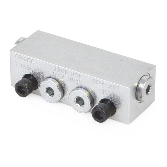
Page 21: Msp Series/Msp Sst Series
MSP Series/MSP SST Series MSP Series/MSP SST Series Technical Specifications Material Corrosion Protected Steel (optional: Type 303 Stainless Steel) Pressure (max) 1500 psi (10.3 MPa, 103.4 bar) Zero Leak Inlet 3000 psi (20.7 MPa, 206.8 bar) Shunt/Shutoff Inlet Ambient Temperature (max) 140°F (60°C) Lubricant Oil Only - up to 5000 SUS, requires 25 micron (min) fil-... -
Page 22: Dimensions (Inches / Mm)
MSP Series/MSP SST Series Dimensions (inches / mm) CROSSPORT PLATE (OPTIONAL) ti11478 Dimension A Style Tab(s) Number of Sections inch CR Right Right CL Left Left 3.578 90.881 CB-Both Right and Left 4.500 114.30 Singling None 5.422 137.718 6.344 161.138 7.266 184.556 8.188... -
Page 23: Parts
MSP Series/MSP SST Series Parts Ref Part No. Description Ref Part No. Description 24B482 VALVE, assembly, MSP 30T -SST 562711 VALVE, assembly MSP 05S 24B483 VALVE, assembly, MSP 35T - SST 562712 VALVE, assembly MSP 10S 562760 VALVE, assembly, MSP 40T - SST 562713 VALVE, assembly MSP 15S 24B497 BLOCK, base, MSP, NPTF, SST... - Page 24 MSP Series/MSP SST Series 5 or 6 312497ZAB...
-
Page 25: Mhh Series
MHH Series MHH Series Technical Specifications Material Steel Body (corrosion protected) Steel Piston (honed fit) Pressure (max) 7,500 psi (52 MPa, 517 bar) for Petroleum or Synthetic Oil - fluoroelastomer O-rings Lubricant Petroleum or synthetic oil only Maximum Operating Temperature Fluoroelastomer O-rings (557722) 350°F (163°C) Maximum Cycle Rate Without Cycle Pin... -
Page 26: Dimensions (Inches / Mm)
MHH Series Dimensions (inches / mm) 2.188 1.656 (55.56) (42.06) 1.125 (28.58) .406 (10.31) LUBE .734 3.000 OUTLET (18.85) (76.2) .625 (TYPICAL) 1.750 (15.9) (44.4) PISTON ENCLOSURE .484 PLUG (TYPICAL) .922 (TYP) (12.3) (23.41) "A" MOUNTING SCREW (TYPICAL) OUTLET IS PLUGGED ON ONE SIDE WHEN WORKING SECTION IS SINGLED... -
Page 27: Parts
MHH Series Parts Ref Part No. Description Ref Part No. Description 560943 BLOCK, inlet, MHH, SAE 562679 VALVE, assembly MHH 06S 560976 BLOCK, inlet, MHH, ISO 6149 562680 VALVE, assembly MHH 09S 563421 BLOCK, inlet, MHH, NPSF, w/bleed 562681 VALVE, assembly MHH 12S 563422 BLOCK, inlet, MHH SAE w/bleed 24X029 VALVE, assembly MHH 15S 563279 BLOCK, MHH end w/alt inlet... -
Page 28: Mxp Series
MXP Series MXP Series Technical Specifications Material Zinc Plated Steel Pressure (max) 3,000 psi (20.7 MPa, 206.8 bar) Lubricant Oil or grease Maximum Operating Temperature 350°F (177°C) Maximum Cycle Rate With Cycle Pin 60 CPM Maximum Cycle Rate Without Cycle Pin or With Prox 110-200 CPM* Cycle Switch Net Weight (approx.) -
Page 29: Dimensions (Inches / Mm)
MXP Series Dimensions (inches / mm) CROSS PORT PLATE OPTIONAL LUBE INLET INDICATOR PORT LUBE OUTLET (OPTIONAL) Style Tab(s) Number Dimension A Dimension B Weight inch inch pound CR Right Right Sections CL Left Left 6.66 169.21 5.35 135.89 18.2 CB-Both Right and Left 8.01... -
Page 30: Parts
MXP Series Parts Ref Part No. Description Ref Part No. Description 562834 VALVE, single, .150 MXP w/indicator 562813 VALVE, twin, .025 MXP 563519 BLOCK, BSPLT interm MXP 1/4 NPSF 562814 VALVE, twin, .050 MXP 563521 BLOCK, BSPLT interm MXP SAE 562815 VALVE, twin, .075 MXP 563522... -
Page 31: Mgo Series
MGO Series MGO Series Technical Specifications Material Zinc Plated Steel and Phosphate Coated Cast Iron Pressure (max) 3-7 section divider valve assembly 6000 psi (41 MPa, 414 bar) 8 section divider valve assembly 5500 psi (38 MPa, 379 bar) 9 section divider valve assembly 5000 psi (34 MPa, 345 bar) 10 section divider valve assembly 4500 psi (31 MPa, 310.3 bar) -
Page 32: Dimensions (Inches / Mm)
MGO Series Dimensions (inches / mm) Dimension A Dimension B Dimension C Divider Valve inch inch inch MGO - 3 10.04 255.1 11.00 279.4 8.58 217.8 11.78 299.1 12.75 323.8 10.31 261.9 MGO - 4 MGO - 5 13.51 343.2 14.50 368.3 12.05... -
Page 33: Parts
MGO Series Parts Ref Part No. Description 562570 VALVE, MGO, assembly 150S SAE 562571 VALVE, MGO, assembly 300S SAE 562572 VALVE, MGO, assembly 450S SAE 562573 VALVE, MGO, assembly 600S SAE 562574 VALVE, MGO, assembly 150T SAE 562575 VALVE, MGO, assembly 300TS SAE 562576 VALVE, MGO, assembly 450T SAE 562577 VALVE, MGO, assembly 600T SAE 562578 VALVE, MGO, assembly 150S SAE IND... -
Page 34: Mx Series
MX Series MX Series Technical Specifications Material Plated Steel Pressure (max) 3,000 psi (21 MPa, 206.8 bar) Lubricant Oil or grease Maximum Operating Temperature 200°F (93°C) Maximum Cycle Rate With Cycle Pin 60 CPM Maximum Cycle Rate Without Cycle Pin 200 CPM Net Weight (approx.) 21-lb. -
Page 35: Dimensions (Inches / Mm)
MX Series Dimensions (inches / mm) Dimension A Dimension B Dimension C Number of Sections inch inch inch 5.08 128.9 5.61 142.5 6.63 168.3 157.5 6.74 171.1 7.75 196.9 7.33 186.1 7.86 199.6 8.88 225.4 8.45 214.7 8.99 228.2 10.00 254.0 9.58 243.2... -
Page 36: Parts
MX Series Parts Ref Part No. Description 562514 VALVE, MX assembly 25S 562515 VALVE, MX assembly 25T 562516 VALVE, MX assembly 50S 562517 VALVE, MX assembly 50T 562538 VALVE, MX assembly 75S 562539 VALVE, MX assembly 75T 562540 VALVE, MX assembly 100S 562541 VALVE, MX assembly 100T 562542 VALVE, MX assembly 125S 562543 VALVE, MX assembly 125T... -
Page 37: Accessories
Accessories Accessories Tube Clips Mounting Brackets Clips are plated and provided with 17/64 in. (6.75 mm) All mounting brackets include screws, lock washers and mounting holes. nuts. Part No. Description Part No. Description 557324 Holds 1 - 1/4 in. (6.35 mm) OD tube 563435 MSP and MH, M-3 and M-4, 1/8 in. -
Page 38: Automatic Relief Indicator
Accessories Automatic Relief Indicator An automatic relief indicator pinpoints lube line blockage but allows the lube system to continue supplying lubricant to points that are not blocked. They are used primarily in secondary divider valves. The excessive pressure created by line blockage moves a piston, enabling the lubricant to escape through a vent. When pressure is relieved the spring resets the piston. -
Page 39: Rupture-To-Atmosphere Indicator
Accessories Rupture-to-Atmosphere Indicator Rupture-to-Atmosphere Indicators are standard on all Graco pumps. When the pressure reaches a predetermined pressure setting, the pressure disc ruptures, venting lubricant into the atmosphere and relieving pressure. Description Pressure PSI* (MPa, Bar) Complete Assembly Replacement Disc Color... -
Page 40: Rupture Discs
Accessories Rupture Discs All discs have a 11/16 in. diameter. Description Pressure PSI* Single Disc Disc Color Quantity 6/package (MPa, bar) 900 (6.2 62) 557431 Black 1175 (8.1, 81) 557432 Green 1450 (10, 100) 557433 Yellow 563962 1750 (12, 121) 557434 563963 2050 (14, 141) -
Page 41: Cycle Counters - Part No. 563444
Accessories Cycle Counters - Part No. 563444 The cycle counter assures that the lubricant is flowing through the system. Every count indicates one complete cycle of the divider valve. Visual inspection and recording of counts provides a constant check on the performance of the lubricant system and the pump. -
Page 42: Proximity Cycle Switches
Accessories Proximity Cycle Switches The proximity cycle switches are magnetically operated single throw switches that sense the movement of the divider valve piston when it is cycling. Each proximity cycle switch provides a signal that is used to monitor the system. -
Page 43: Proximity Switch Connection Cables
Accessories Proximity Switch Connection Cables Connection Cables for: 3-Pin Proximity Switch 5-Pin Proximity Switch Connector Length - ft (m) Part No. Connector Length - ft (m) Part No. Straight 6 (1.83) 558021 Straight 6 (1.83) 558023 Straight 12 (3.66) 558022 Straight 12 (3.66) 558024... -
Page 44: Maximum Cycle Rate And Flow Guidelines
Maximum Cycle Rate and Flow Guidelines Maximum Cycle Rate and Flow Guidelines Smallest Number of Sections Piston Assembly Smallest Number of Sections Piston Assembly 312497ZAB... -
Page 45: California Proposition 65
California Proposition 65 California Proposition 65 CALIFORNIA RESIDENTS WARNING: Cancer and reproductive harm – www.P65warnings.ca.gov. 312497ZAB... -
Page 46: Graco Standard Warranty
With the exception of any special, extended, or limited warranty published by Graco, Graco will, for a period of twelve months from the date of sale, repair or replace any part of the equipment determined by Graco to be defective.
Need help?
Do you have a question about the Trabon MD Series and is the answer not in the manual?
Questions and answers