Table of Contents
Advertisement
Quick Links
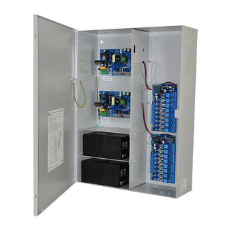
Maximal F Series
Dual Power Supply
Access Power Controllers (fused)
Models Include:
Maximal11F
- Power Supply 1:
12VDC @ 3.3A or 24VDC @ 3.6A.
- Power Supply 2:
12VDC @ 3.3A or 24VDC @ 3.6A.
- Sixteen (16) fuse protected
power-limited outputs.
Maximal33F
- Power Supply 1:
12VDC @ 5.3A or 24VDC @ 5.6A.
- Power Supply 2:
12VDC @ 5.3A or 24VDC @ 5.6A.
- Sixteen (16) fuse protected
non power-limited outputs.
Installation Guide
Rev. MDFF052319
Installing Company: _______________ Service Rep. Name: __________________________________
Address: _____________________________________________ Phone #: __________________
Altronix Corp.
140 58th St. Brooklyn, NY
Maximal55F
- Power Supply 1: 12VDC @ 9.3A.
- Power Supply 2: 12VDC @ 9.3A.
- Sixteen (16) fuse protected
non power-limited outputs.
Maximal75F
- Power Supply 1: 12VDC @ 9.3A.
- Power Supply 2: 24VDC @ 9.6A.
- Sixteen (16) fuse protected
non power-limited outputs.
Maximal77F
- Power Supply 1: 24VDC @ 9.6A.
- Power Supply 2: 24VDC @ 9.6A.
- Sixteen (16) fuse protected
non power-limited outputs.
More than just power.
TM
Advertisement
Table of Contents

Subscribe to Our Youtube Channel
Related Manuals for Altronix Maximal F Series


Summary of Contents for Altronix Maximal F Series
- Page 1 Maximal F Series Dual Power Supply Access Power Controllers (fused) Models Include: Maximal11F Maximal55F - Power Supply 1: - Power Supply 1: 12VDC @ 9.3A. 12VDC @ 3.3A or 24VDC @ 3.6A. - Power Supply 2: 12VDC @ 9.3A. - Power Supply 2: - Sixteen (16) fuse protected 12VDC @ 3.3A or 24VDC @ 3.6A.
-
Page 2: Table Of Contents
Maximal F Series Configuration Chart ........ -
Page 3: Maximal F Series Overview
The fire alarm disconnect feature is individually selectable for any or all of the sixteen (16) outputs. All interconnecting equipment must be UL Listed. Maximal F Series Configuration Chart: Nominal DC Output Voltage Options... -
Page 4: Agency Listings
• ACM8 board main fuses are rated @ 10A. Output fuses are rated @ 3.5A. eFlow Power Supply/Charger: • Input: 120VAC, 60Hz. • For output voltage and supply current refer to Maximal F series Configuration Chart, pg. 3. • Auxiliary Class 2 Power-Limited output rated @ 1A (unswitched). • Overvoltage protection. -
Page 5: Maximal F Installation Instructions
Maximal F Installation Instructions: Wiring methods shall be in accordance with the National Electrical Code/NFPA 70/ANSI, the Canadian Electric Code, Part I, Part II and with all local codes and authorities having jurisdiction. Product is intended for indoor use only. Power Supply Board LED Diagnostics (pg. - Page 6 14. Installation of Tamper Switch (Fig. 3a, pg. 10): Mount UL Listed tamper switch (Altronix model TS112 or equivalent) at the top of the enclosure. Slide the tamper switch bracket onto the edge of the enclosure approximately 2” from the right side (Fig. 3a, pg. 10).
-
Page 7: Maintenance
Output Voltage Test: Under normal load conditions, the DC output voltage should be checked for proper voltage level (refer to Maximal F series Configuration Chart, pg. 3). Battery Test: Under normal load conditions check that the battery is fully charged, check specified voltage at the battery terminals and at the board terminals marked [+ BAT –] to ensure that there is no break in the battery connection wires. -
Page 8: Power Supply Board Terminal Identification
Power Supply Board Terminal Identification: Terminal Legend Function/Description Connect 120VAC 60Hz to these terminals: L to hot, N to neutral. L, G, N Do not use terminal marked [G]. + DC – Factory connected to ACM8 board. Trigger EOL Fire Alarm Interface trigger input from a short or FACP. Trigger inputs can be normally open, Supervised normally closed from an FACP output circuit (Class 2 power-limited input) (Fig. -
Page 9: Power Supply Board Output Voltage Settings
Power Supply Board Output Voltage Settings: Fig. 1a OFF - 24V ON - 12V Access Power Controller Typical Application Diagram (for each ACM8): Fig. 2 Fig. 2a Intact = Dry Input Normally Open (N.O.) Cut = Wet Input Door Releasing FACP FACP Device... -
Page 10: Maximal F Battery Hookup And Tamper Switch Installation
Fig. 3 - Maximal F Series Tamper Switch OFF - 24V ON - 12V Power Supply Board AC DC NC C NO NC C NO TRIGGER +AUX- AC FAIL BAT FAIL SUPERVISED RESET Line Neutral Earth Ground OFF - 24V... -
Page 11: Nec Power-Limited Wiring Requirements
NEC Power-Limited Wiring Requirements: Power-limited and non power-limited circuit wiring must remain separated in the cabinet. All power-limited circuit wiring must remain at least 0.25” away from any non power-limited circuit wiring. Furthermore, all power-limited circuit wiring and non power-limited circuit wiring must enter and exit the cabinet through different conduits. One such example of this is shown below. -
Page 12: Facp/Optional Power Supply Hook-Up Diagrams
FACP Hook-Up Diagrams: Fig. 5 Optional hook-up using two (2) isolated Fig. 6 Polarity reversal input from FACP power supply inputs (Only applicable on signaling circuit output (polarity is Maximal11F, not evaluated by UL): referenced in alarm condition): CUT JUMPERS JUMPER J1 AND J2 FACP... - Page 13 Notes: Maximal11F/33F/55F/75F/77F Series Access Power Controllers (Fused) Installation Guide - 13 -...
- Page 14 Notes: - 14 - Maximal11F/33F/55F/75F/77F Series Access Power Controllers (Fused) Installation Guide...
-
Page 15: Enclosure Dimensions
(21.6mm) 4” (101.6mm) 2” (50.8mm) 19” (482.6mm) Altronix is not responsible for any typographical errors. –––––––––––––––––––––––––––––––––––––––––––––––––––––––––––––––––––––––––––––––––––––––––––––––––––––––––––––––– 140 58th Street, Brooklyn, New York 11220 USA | phone: 718-567-8181 | fax: 718-567-9056 website: www.altronix.com | e-mail: info@altronix.com | Lifetime Warranty IIMaximal11F/33F/55F/75F/77F Series... - Page 16 - UL Listed in the U.S. and Canada. - Local or remote control of up to (2) two Altronix eFlow power output(s) via LAN and/or WAN. - Monitor real time diagnostics: DC output voltage, output current, AC & battery status/service, input trigger state change, output state change and unit temperature.
Need help?
Do you have a question about the Maximal F Series and is the answer not in the manual?
Questions and answers