Table of Contents
Advertisement
Available languages
Available languages
Quick Links
Stampato su carta reciclata - Nessun albero è stata abbattuto
- Marchio "Angelo Blu" ⁄ Printed on resycled paper - no trees
have been cutted down - mark "Blue Angel"
Ego 2 easy
.................................................................................................................................. 1
Istruzioni per l'installazione e l'uso ..................................................................................................
Ego 2 easy
................................................................................................................................ 21
Installation and operating manual ....................................................................................................
Advertisement
Chapters
Table of Contents

Related Manuals for EBARA Ego 2 easy


Summary of Contents for EBARA Ego 2 easy
- Page 1 Ego 2 easy ..........................1 Istruzioni per l’installazione e l’uso ....................Ego 2 easy ..........................21 Installation and operating manual ....................Stampato su carta reciclata - Nessun albero è stata abbattuto - Marchio “Angelo Blu” ⁄ Printed on resycled paper - no trees...
-
Page 2: Table Of Contents
Italiano (IT) Manuale di utilizzo e installazione SOMMARIO Informazioni generali ........................... 22 Destinazione d’uso ............................. 22 Identificazione della pompa ........................23 Manutenzione della pompa, parti di ricambio e messa fuori servizio ............23 Sicurezza .............................. 23 Specifiche tecniche ..........................24 Norme e meccanismi di protezione ...................... -
Page 3: Informazioni Generali
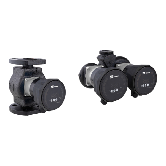
INFORMAZIONI GENERALI DESTINAZIONE D’USO Le pompe di circolazione Ego 2 (T) easy vengono utilizzate per il trasporto del fluido all'interno di sistemi di distribuzione di acqua calda per riscaldamento, sistemi di condizionamento dell'aria e ventilazione. Sono progettate come gruppi pompanti singoli o doppi a velocità... -
Page 4: Identificazione Della Pompa
IDENTIFICAZIONE DELLA POMPA Ego (T) 2 easy (-/C) 40/120 Pump family Twin pump Bronze hydraulic casting 2 easy Pump name (-/C) Communication Nominal pipe diameter Maximum head (in 0.1 m of H (F = Flange connection type) MANUTENZIONE DELLA POMPA, PARTI DI RICAMBIO E MESSA FUORI SERVIZIO Il presente prodotto e i suoi componenti devono essere smaltiti in modo rispettoso dell'ambiente. -
Page 5: Specifiche Tecniche
FLUIDO DELLA POMPA Le pompe di circolazione Ego 2 easy sono destinate alla circolazione dei liquidi nei sistemi di riscaldamento centrale, della ventilazione e dei climatizzatori. La versione Ego 2 B easy , con corpo in acciaio , viene usata in impianti ad uso sanitario. Differiscono dalle pompe di circolazione standard a velocità... - Page 6 TEMPERATURE AMBIENTE UMIDITÀ Temperatura ambiente e temperatura del fluido consentite: Temperatura Temperatura del fluido [°C] Umidità relativa ambiente [°C] min. max. dell’ambiente circostante Fino a 25 Fino a 30 < 95 % Fino a 35 Fino a 40 • La temperatura del fluido deve essere superiore o uguale alla temperatura ambiente per evitare l'accumulo di condensa sulla superficie della pompa.
-
Page 7: Specifiche Elettriche
SPECIFICHE ELETTRICHE Valori elettrici Potenza Corrente Avviame Pompa Tensione nominale nominale nominale ) [A] Ego 2 (T) easy xx/40 230 VAC ± 15 %, 47-63 Hz Ego 2 (T) easy xx/60 0,75 Le pompe possono operare Circuito Ego 2 (T) easy xx/80 a tensione ridotta con 1,15 di avvio... - Page 8 3.4.2.2 RELÈ OUTPUT Disponibile solo nella variante Ego 2 (T) easy C. Proprietà elettriche Corrente nominale Voltaggio Massimo 250 VAC, 30 VDC Potenza massima 300 VA 3.4.2.3 ETHERNET Disponibile solo nella variante Ego 2 (T) easy C. Proprietà elettriche Connettori RJ-45, 10BASE-T, 10 Mbit/s.
- Page 9 3.4.2.4 MODBUS Disponibile solo nella variante Ego 2 (T) easy C. Specifiche Modbus Protocollo dati Modbus RTU Connettore Screwless terminals 2+1 pins. Modbus Tipo RS-485 connessione Modbus Configurazione Due fili + comune Conduttori: A, B e COM (Common). cavo Modbus Trasmettitore Integrato, Connessione passiva o daisy chain.
-
Page 10: Installazione Della Pompa
INSTALLAZIONE DELLA POMPA INSTALLAZIONE NELLA CONDOTTA La pompa deve essere installata nelle tubazioni con l'asse del motore elettrico in posizione orizzontale (figura 1) e in una delle posizioni consentite (figura 2). La freccia di direzione sull'alloggiamento idraulico mostra la direzione del flusso d'acqua. Affinché la pompa funzioni con vibrazioni e rumore minimi, si consiglia di installare la pompa in una parte della tubazione senza curve per almeno 5 D (D = diametro nominale del tubo) da entrambi i lati dell'alloggiamento idraulico. -
Page 11: Impianto Elettrico
IMPIANTO ELETTRICO Il collegamento elettrico si effettua con il connettore fornito a corredo della pompa Segnale Descrizione 230 VAC, alimentazione con energia elettrica Messa a terra di sicurezza La pompa è dotata di fusibile per la protezione da sovracorrente, protezione termica e protezione di base contro la sovratensione. Non ha bisogno di un ulteriore interruttore termico. -
Page 12: Regolazione E E Funzionamento
REGOLAZIONE E FUNZIONAMENTO GESTIONE E FUNZIONI Tutte le pompe dispongono di: • Schermo – consente di monitorare e controllare e le modalità operative della pompa, i parametri e lo stato di accensione/spegnimento della pompa. La versione Ego 2 (T) easy C dispone di: •... - Page 13 DISPLAY Tramite il monitor è possibile controllare e visualizzare le modalità operative della pompa, l'accensione / lo spegnimento, i parametri della pompa e gli errori. Per le descrizioni delle modalità operative della pompa, consultare il capitolo 5.2 “Funzionamento”. 1. Rappresentazione grafica a colonne dei parametri della pompa 2.
- Page 14 Tasto Pressione breve: • per scorrere tra i parametri dal basso verso l’alto quando non si modificano i valori dei parametri, per scorrere tra le modalità operative dal basso verso l’alto quando è attiva la selezione della modalità operativa, • •...
- Page 15 RELÈ OUTPUT Configurazione disponibile solamente nella versione Ego 2 (T) easy C. Configurazione C module Descrizione funzione Predefinito Il relè è in posizione attiva solo quando la pompa è Errore per relè 2 accesa ed è presente un errore. Il relè è in posizione attiva quando la pompa è Predefinito Pronto accesa e non si sono verificati errori.
- Page 16 Le pompe della versione “C” hanno tre ingressi/uscite analogici con funzioni diverse. Possono essere configurati tramite l'interfaccia di rete (pagina “pompa”) o tramite Modbus. Ingressi/Uscite Funzione Descrizione funzione Run [predefinito – Modalità Attivazione/disattivazione della pompa. In base alle SET1 impostazioni predefinite si attiva collegandosi a SET3. operativa 1] Impostare la pompa sulle impostazioni massime quando MAX II/Min [predefinito –...
- Page 17 Posizione dell’interruttore Funzione Descrizione della modalità operativa Le funzioni del terminale vengono configurate tramite Configurazione della rete l'interfaccia di rete. SET1= RUN ingresso SET2= MAX ingresso SET3 = FB (10.5 V) uscita, si può utilizzare per alimentare gli Modalità operativa 1 ingressi RUN e MAX.
- Page 18 ETHERNET Disponibile solamente nella configurazione Ego 2 (T) easy C. La pompa dispone di un server web integrato che consente l'accesso diretto alla pompa tramite una connessione Ethernet esistente. L'indirizzo predefinito per accedere alla pompa è 192.168.0.245/. Il server web utilizza pagine HTML per regolare e visualizzare: impostazioni della modalità...
-
Page 19: Modalità Operative
MODALITÀ OPERATIVE La pompa può funzionare in 5 diverse modalità. Possiamo impostare la pompa nella modalità operativa più adatta, a seconda dell'impianto in cui opera la pompa. Modalità operativa della pompa: • Modalità automatica (impostazione di fabbrica), • Pressione proporzionale •... - Page 20 FUNZIONAMENTO POMPE GEMELLARI Le pompe doppie hanno un doppio alloggiamento idraulico con valvola di non ritorno integrata, che gira automaticamente in base alla portata, e due motori separati. Ego 2 (T) easy le pompe non hanno una logica di controllo che garantisca il funzionamento continuo di almeno una pompa - la logica di controllo deve essere eseguita dal cliente/utente stesso.
-
Page 21: Errori E Soluzioni Dei Problemi
ERRORI E RISOLUZIONE DEI PROBLEMI In caso di guasto della pompa, sullo schermo viene visualizzato un codice di errore. Codice di Descrizione Probabile causa errore Errore di carico E10 (dry) Basso carico del motore Basso carico rilevato. La pompa funziona senza fluido. Elevato carico del motore Guasto al motore o presenza di fluido viscoso. - Page 22 English (EN) Installation and operating manual TABLE OF CONTENTS General information ..........................22 Uses ................................22 Pump labeling ............................23 Pump maintenance, spare parts and decommissioning ................23 Safety ..............................23 Tehnical specifications ......................... 24 Standards and protections ......................... 24 Pump medium ............................
-
Page 23: General Information
GENERAL INFORMATION USES The Ego circulating pumps are used for the transfer of liquid medium within systems for hot-water heating, air-conditioning and ventilation. They are designed as single or twin variable-speed pumping aggregates where the speed is regulated by electronic device. -
Page 24: Pump Labeling
PUMP LABELING Ego (T) 2 easy (-/C) 40/120 Ego 2 easy Pump family Modbus version Twin pump Maximum pressure (dm) Bronze hydraulic casting Nominal inlet diameter (DN) 2 easy Pump name Range (-/C) Communication Twin Version Nominal pipe diameter Model Maximum head (in 0.1 m of H (F = Flange connection type) PUMP MAINTENANCE, SPARE PARTS AND DECOMMISSIONING... -
Page 25: Tehnical Specifications
TEHNICAL SPECIFICATIONS STANDARDS AND PROTECTIONS Pumps are made in according to the following standards and protections: Protection class: Insulation class: Motor protection: IP44 Thermal - built in Installation specification Pump type Nominal pressure Fitting length [mm] EGO 2 (T) EASY 25/40 EGO 2 (T) EASY 25/60 EGO 2 (T) EASY 25/80 EGO 2 (T) EASY 25/100... -
Page 26: Temperatures And Ambient Humidity
TEMPERATURES AND AMBIENT HUMIDITY Permitted ambient and media temperature: Ambient temperature Medium temperature [°C] Relative ambient humidity [°C] min. max. Up to 25 < 95 % • Medium temperature should be higher or the same as ambient temperature, so that the condensate does not gather on pump surface. -
Page 27: Electrical Specification
ELECTRICAL SPECIFICATION POWER SUPPLY Electrical properties Rated Rated current Pump Rated voltage Startup power [W] ) [A] Ego 2 (T) easy xx/40 230 VAC ± 15 %, 47-63 Hz Ego 2 (T) easy xx/60 0,75 Build-in Pumps can operate at power (����... - Page 28 3.4.2.2 RELAY OUTPUT Only available in variant Ego 2 (T) easy C. Electrical properties Rated current Maximum voltage 250 VAC, 30 VDC Maximum power 300 VA 3.4.2.3 ETHERNET Only available in variant Ego 2 (T) easy C. Electrical properties Connector RJ-45, 10BASE-T, 10 Mbit/s.
- Page 29 3.4.2.4 MODBUS Only available in variant Ego 2 (T) easy C. Modbus specification Data protocol Modbus RTU Modbus connector Screwless terminals 2+1 pins. Modbus connection RS-485 type Modbus wire Two-wire + common Conductors: A, B and COM (Common). configuration Communication Integrated, Connect either via passive taps or daisy chain.
-
Page 30: Pump Installation
PUMP INSTALLATION INSTALLATION INTO PIPE LINES The pump must be installed into pipe lines with its electromotor axis in horizontal position (figure 1) and in one of the allowed positions (figure 2). Direction arrow on hydraulic housing shows direction of water flow. For pump to operate with minimal vibrations and noise, it is recommended to install pump in part of the pipe line without curves for at least 5 D (D = rated pipe diameter) from both side of hydraulic housing. -
Page 31: Electrical Installation
ELECTRICAL INSTALLATION Electrical connection is done with connector supplied with the pump. Markings Descriptions 230 VAC, electric power supply Safety ground The pump has a built-in over current fuse and protection, temperature protection and basic overvoltage protection. It doesn’t need an additional thermal protection switch. Connection leads should be capable of carrying rated power and should be properly fused. -
Page 32: Setup And Operation
SETUP AND OPERATION CONTROL AND FUNCTIONS All pumps feature: Display panel - it controls and overviews pump modes, parameters and on/off status. • Variant Ego 2 (T) easy C features: 10-step switch - it allows us to change relay output, analog inputs/outputs and resetting the pumps •... - Page 33 DISPLAY PANEL With the use of the display panel, you can control and overview pump modes, on/off control, pump parameters and errors. To see how pump modes work, see chapter 5.2 Operation. 9. Bar graph display of pump parameters Numerical display of values Unit display Display of the currently selected mode Night mode...
- Page 34 Short press: • Scrolling through parameters upwards when not changing parameter values, scrolling through modes upwards when mode selection is selected, • • changing parameters upwards when setting parameter values. Long press: • 3 seconds together with puts us in night mode, 5 seconds together with keys to restore pump to factory settings.
- Page 35 RELAY OUTPUT Relay output configuration is only possible in variant Ego 2 (T) easy C. Configuration S module U module C module Function description Fault Default for Default for The relay is in active position only when the pump (error) Relay 2 Relay 2 is powered up and an error is present.
- Page 36 C variant pumps have three analog inputs/outputs with different functions. They can be configured through the web interface (page “pump”) or through Modbus. Input/Output Function Function description Turning the pump on/off. By default activating with Run [Default - Mode 1] SET1 connection to SET3.
- Page 37 ETHERNET Only available in variant Ego 2 (T) easy C. The pump has a built-in web server which allows you to access your pump directly via an existing Ethernet connection. The default address for access to the pump is 192.168.0.245/ The web server uses HTML pages to set/view: Regulation mode settings, •...
-
Page 38: Operation
OPERATION The pump can operate in 5 different modes. We can set the pump in the most appropriate mode, depending on the system where the pump operates. The pump modes: Automatic mode (factory default), • • proportional pressure, constant pressure, •... - Page 39 TWIN PUMP OPERATION Twin pumps have double hydraulic housing with integrated check valve, which automatically turns based on flow, and two separated motors. Ego 2 (T) easy pumps do not have a control logic that ensures the continuous operation of at least one pump - the control logic must be carried out by the customer / user himself.
-
Page 40: Error And Troubleshooting
ERROR AND TROUBLESHOOTING If pump failure occurs, the error code will appear on the display. Error code Description Probable cause Load errors E10 (dry) Low motor load Low load detected. Pump is running dry. High motor load Motor might be faulty or viscous medium is present. Protection active Circuit is too hot and power was reduced to less than 2/3 of rated E22 (hot) - Page 41 PUMP CURVES/CURVE Ego (T)(C) easy -/40 Ego (T)(C) easy -/60 Ego (T)(C) easy -/100 Ego (T)(C) easy -/80 Ego (T)(C) easy -/120...
- Page 42 PICTURES picture 1 picture 2...
- Page 43 picture 3 picture 4...
- Page 48 Cod. Rev. - 01.2024 EBARA Pumps Europe S.p.A. EBARA Pumps Europe S.p.A. UK EBARA POMPY POLSKA Sp. z o.o. Via Torri di Confine 2/1 int. C Unit A, Park 34 ul. Działkowa 115 A 36053 Gambellara (Vicenza), Italy Collett Way - Didcot...
Need help?
Do you have a question about the Ego 2 easy and is the answer not in the manual?
Questions and answers