Table of Contents
Advertisement
Quick Links
No. 20111-2-01-21
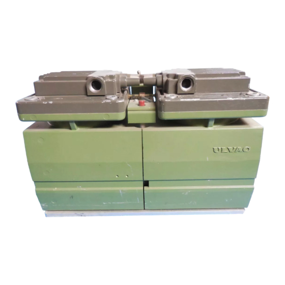
DIAPHRAGM DRY VACUUM PUMP
INSTRUCTION MANUAL
MODEL DA-60D
MODEL DA-120S
Prior to use
For safe and efficient use of this pump, please read this manual
carefully before operation.
After reading the manual, keep it in your file for future reference.
Specifications in this manual are subject to change without notice
due to future improvement.
ULVAC KIKO,Inc.
Advertisement
Table of Contents

Related Manuals for Ulvac DA-60D


Summary of Contents for Ulvac DA-60D
- Page 1 No. 20111-2-01-21 DIAPHRAGM DRY VACUUM PUMP INSTRUCTION MANUAL MODEL DA-60D MODEL DA-120S Prior to use For safe and efficient use of this pump, please read this manual carefully before operation. After reading the manual, keep it in your file for future reference.
-
Page 2: Table Of Contents
Contents Pages with a shaded background are those which contain items related to safety. Before Using the Equipment ......................01 Checks When Opening Packaging ....................02 Using the Pump Safely ........................03 ・Safety icons .......................... 03 ・Cautions for Safety in Use ....................04 1.Product Outline .......................... - Page 3 Figures and Tables Fig.2.1 DA-60D Dimensions ......................2 Fig.2.2 DA-120S Dimensions ......................2 Fig.3.1 Change region of the voltage and frequency ................ 4 Fig.3.2 Example of Piping Used When Evacuating a Vessel ............5 Table 1.1 Product Specifications (50/60 Hz) ..................1...
-
Page 4: Before Using The Equipment
Before Using the Equipment Thank you for purchasing this product. Your custom is very much appreciated. This pump is designed solely for vacuum discharge, and may malfunction or cause accidents if not handled appropriately. Read the manual thoroughly, and pay due attention to inspections, maintenance, and safety. -
Page 5: Checks When Opening Packaging
Contact your agent or the sales division of the manufacturer if there are any problems with the pump. ! Note Do not hold or push the tube at the top of the pump while removing it from the packaging. Damage to the tube may affect performance of the pump. DA-60D DA-120S Tube dD 02... -
Page 6: Using The Pump Safely
Using the Pump Safely To ensure that the pump is handled correctly, read this section thoroughly before use. This manual and the warning labels on the pump include safety icons as an aid to understanding safety requirements. These safety icons warn the operator and others of possible dangers and damage and should always be followed. -
Page 7: Cautions For Safety In Use
・Cautions for Safety in Use Danger Applications (1) This pump is not designed to be explosion-proof, and should therefore not be used to discharge explosive gases. (2) In addition to discharge of gas via the outlet, gas may also leak from other parts of the pump, and it should therefore not be used with toxic gases. - Page 8 Warning Operation (14) This pump is not designed to be explosion-proof. When using the pump, ensure that there are no inflammable materials such as solvents, or explosive gases, in the vicinity. Use under such conditions may result in injury or fire. (15) Inserting fingers or objects into the motor inlet may result in electric shock, injury, or fire.
- Page 9 Caution Operation (4) Touching rotating components (eg motor, main shaft, axial joints, cooling fan) while the pump is in operation may result in injury. (5) The overload protector operates when the pump becomes excessively hot. Touching it in this condition may result in burns. (6) Touching the motor while the pump is in operation or while it is still hot immediately after having been switched off may result in burns.
- Page 10 (2) Do not hold or push the tube at the top of the pump (see below). Damage to the tube may affect performance of the pump. Tube DA-60D DA-120S Applications (3) This pump is not designed to be corrosion-proof. Use it only with clean air at normal temperature, or with gases of equivalent characteristics.
-
Page 11: Product Outline
(4) Do not attempt to discharge gases containing particles, dust, water, or corrosive gases. (5) Do not operate the pump for long periods at near-atmospheric pressure. 1.2 Specifications Table 1.1 Product Specifications (50/60 Hz) Model DA-60D DA-120S Pumping Speed 50Hz 60L/min 120L/min 60Hz... -
Page 12: Dimensions
115V,200V,220V, a cable termination is “loose end”. ※When motor specification is 220V, the manual reset type thermal protector is not attached. Fig.2.1 DA-60D Dimensions ※When motor specifications are 115V,200V,220V, a cable termination is “loose end”. ※When motor specification is 220V, the manual reset type thermal protector is not attached. -
Page 13: Installation And Storage
3. Installation and Storage 3.1 Cautions for Installation and Storage See Warning Warning (1)(2)(3)(5)(6)(7)(8)(9)(10)(11)(12)(13), P04 See Caution (1)(2)(3), P05 Caution See Note (1)(2), P07 Note 3.2 Environmental Conditions for Installation, Storage, and Operation The fine clearances used in this pump require that the following conditions be satisfied during storage, installation, and operation. -
Page 14: Fluctuations In The Power Voltage And Frequency
3.5 Fluctuations in the power voltage and frequency Standard: Rotation electricity machine general rules JIS C 4034-1:1999,JEC-2137-2000 To the voltage change and frequency change in Domain A, in main rated values, it operates continuously, and can be used practically convenient, and to the voltage change and frequency change in Domain B, it shall operate with main rated values and shall be used practically convenient. -
Page 15: Checking Operation After Installation
3.6 Checking Operation After Installation 1) Remove the rubber caps from the inlet and outlet. 2) Check that the pump switch is OFF (set to O), and connect the power supply. Note: Ensure that the power cord is sufficient for the rated voltage and current. Note: Extension cords should be 3-wire, with lead wires having a cross-sectional area of at least 1.0 mm 3) Turn the switch ON (set to l) and check that gas is being drawn into the inlet. -
Page 16: Cautions For Operation
4. Cautions for Operation 4.1 Cautions for Operation See Danger (1)(2), P04 Danger See Warning (8)(14)(15)(16), P04, 05 Warning See Caution (4)(6)(7), P06 Caution See Note (3)(4)(5)(6)(7)(8)(9)(10), P07 Note 4.2 Operation of the Thermal Protector 1) When the thermal protector operates, switch the pump power supply OFF (set to O), remove the power cord from the outlet, and contact the manufacturer. -
Page 17: Pump Performance
5. Pump Performance 5.1 Pressure Achieved The term “pressure achieved” as employed in the catalogue and in this manual is defined as “the minimum pressure obtained by the pump without introduction of gas from the pump inlet . Note that the indicator values for pressure may differ between types of vacuum gauges. Pressure achieved in practice, occasionally becomes higher than that noted in the catalogue for the following reasons. -
Page 18: Maintenance, Inspection, And Repair
6. Maintenance, Inspection, and Repair 6.1. Cautions for Maintenance, Inspection, and Repair See Danger (3), P04 Danger See Warning (4)(17)(18), P04, 05 Warning See Caution (8)(9), P06 Caution See Note (11), P07 Note Maintenance and repair by the customer’s repair technician is limited to the following procedures. - Page 19 <Consumables List> Table 6.1 Consumables List(DA-60D,120S) Description Material Life expectancy 6,000~8,000 hrs Diaphragm 2 pcs EPDM 6,000~8,000 hrs Suction/exhaust valve 16 pcs 6,000~8,000 hrs Pump head cover gasket 2 pcs 6,000~8,000 hrs Air filter 2 pcs Urethane foam O-ring(S-14) 6,000~8,000 hrs...
-
Page 20: Replacing And Cleaning Consumables
6.4 Replacing and Cleaning Consumables See Caution (9), P06 Caution The pump becomes very hot after operation. After stopping the pump, leave it ① for 30 minutes to cool, and replace and clean components only after it has cooled to a safe temperature. Use a dust mask and gloves when replacing diaphragms and valves to prevent ②... - Page 21 In the replacement procedure, the terms “primary side” and “secondary side” shall be used to refer to specific locations. Refer to the terms and diagram below when performing the replacement. Exhaust tube Suction tube DA-60D Exhaust tube Suction tube DA-120S...
- Page 22 Parts Removal *First unplug the pump’s power cable from the main power supply. *The picture shown is the DA-60D, but the procedure is the same for the DA-120D. Step 1: Remove (1) the hex socket bolts (M10×22) × Qty.8 (4 each on both the primary and secondary sides), and then remove (2) the pump heads.
- Page 23 Step 2: Remove (1) the small pan head screws (M3×5) Qty. × 4, (2) the exhaust valve holders ((4) the plain washers on the suction side) and (3) the suction/exhaust valves from the pump heads. The valves come in pairs and each one is placed on top of the other.
- Page 24 ii. Attaching Parts & Assembly Step 4: Put the new diaphragm on the connecting rod to replace the old one removed in Step 3. The front and rear sides of the diaphragm are different from each other. Refer to the pictures below to ensure that the front side is the side which is facing up.
- Page 25 Step 6: Using the torque wrench with a bit size of 4 mm (5.0 Nm), fasten the push plates for the diaphragms with hex socket bolts (M5×16) that have Loctite 242 applied onto 5 to 6 threads from their screw tip. When tightening the bolts, do so in the order shown in the picture on the left, going over them three times, gradually tightening each one of them.
- Page 26 Pay attention to the position of the exhaust valves order. *Please note that the mounting orientation of the pump head is different for DA-60D and DA-120S. Refer to the pictures on the left to make sure that the pump heads are attached correctly.
- Page 27 Long outlet. Please note that the mounting position of the Long air filter is different for DA-60D and DA-120S. Refer to the pictures on the left to ensure that the filters are attached correctly. After inserting the air filters, connect the primary and secondary side pump heads with connecting tubes.
- Page 28 *Please note that the mounting orientation of the pump head is different for DA-60D and DA-120S. Refer to the Suction/exhaust pictures on the left to ensure that the outlet Power cord pump heads are attached correctly.
-
Page 29: Troubleshooting List
6.5 Troubleshooting List Table 6.3 Troubleshooting List Problem Causes Solutions Reference (1) Not connected to power supply. (1) Connect power supply. (2) Switch is OFF. (2) Set switch to I. (3) Problem with power supply voltage. (3) Ensure that voltage variation is within +/-10%. -
Page 30: In Conclusion
7. In Conclusion Please contact the manufacturer’s sales division if you have any questions. Warranty (1) The warranty for this pump (this equipment) extends for a period of one year from the date of shipment. (2) Any malfunctions or defects which occur under normal usage conditions during the warranty period will be repaired free of charge. -
Page 31: Usage Status Check Sheet
Usage Status Check Sheet (for use in Instruction Manual) * For the purpose of safety control of repair personnel, fill in within the heavy line frame and attach the sheet to the item of which repair is requested. * In case this sheet were not attached or filled in, your request of repair and service may not be accepted. - Page 32 株式会社アルバック 規格品事業部 東日本営業部 〒253-8543 神奈川県茅ヶ崎市萩園2500 TEL:0467-89-2416 株式会社アルバック 規格品事業部 西日本営業部 〒532-0003 大阪府大阪市淀川区宮原3-3-31 上村ニッセイビル5F TEL:06-6397-2286 ULVAC KIKO,Inc. https://ulvac-kiko.com/en Please contact us for products, Service Base or other Inquiries from here. https://showcase.ulvac.co.jp/en/ ULVAC,Inc. Components Division 2500 Hagisono, Chigasaki, Kanagawa, 253-8543, Japan TEL:+81-467-89-2261...
Need help?
Do you have a question about the DA-60D and is the answer not in the manual?
Questions and answers