Table of Contents
Advertisement
Quick Links
No.27700-2-01-8
INSTRUCTION MANUAL
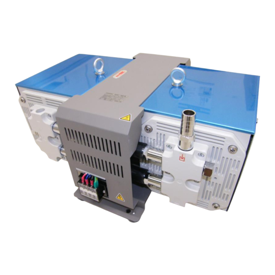
Diaphragm-type Dry Vacuum Pump
Model: DAL-181D, 361S
Request to Users
Please read this manual thoroughly to ensure safe and
effective use of the equipment.
Keep this manual in a safe place.
Due to periodic improvements in performance, the
equipment described in this manual is subject to
changes in dimensions and specifications without prior
notice.
ULVAC KIKO,Inc.
Advertisement
Table of Contents

Related Manuals for Ulvac DAL-181D


Summary of Contents for Ulvac DAL-181D
- Page 1 No.27700-2-01-8 INSTRUCTION MANUAL Diaphragm-type Dry Vacuum Pump Model: DAL-181D, 361S Request to Users Please read this manual thoroughly to ensure safe and effective use of the equipment. Keep this manual in a safe place. Due to periodic improvements in performance, the...
-
Page 2: Table Of Contents
Regular Inspections ......................8 Replacing and Cleaning Consumables ..............10 Cleaning Inlet Filters ....................11 Replacing Diaphragms ....................11 Replacing DAL-181D Unit Valves ................15 Replacing DAL-361S Unit Valves ..………………………………………………….17 Replacing O-rings ..................... 18 Replacing Piping ....................... 19 Replacing Exhaust Filters ..................21... - Page 3 Figures and Tables Fig.2.1 DAL-181D and DAL 361S Dimensions ................. 2 Fig.3.1 Change region of the voltage and frequency ................ 4 Fig.3.2 Wiring Diagram........................4 Fig.3.3 Fitting Piping ........................5 Fig.3.4 Example of Piping Used When Evacuating a Vessel ............5...
-
Page 4: Before Using The Equipment
Before Using the Equipment Thank you for purchasing this product. Your custom is very much appreciated. This pump is designed solely for vacuum discharge, and may malfunction or cause accidents if not handled appropriately. Read the manual thoroughly, and pay due attention to inspections, maintenance, and safety. -
Page 5: Checks When Opening Packaging
Checks When Opening Packaging Check the following after opening the packaging. (1) Is the product as you requested? (2) Are the accessories and necessary parts included? Standard accessories ・User’s manual -------------------- × 1 ・Piping protector cap (supplied with piping) -------------------- × 2 ・Piping (long hose nipple:L-1) -------------------- ×... -
Page 6: Using The Pump Safely
Using the Pump Safely To ensure that the pump is handled correctly, read this section thoroughly before use. This manual and the warning labels on the pump include safety icons as an aid to understanding safety requirements. These safety icons warn the operator and others of possible dangers and damage and should always be followed. -
Page 7: Cautions For Safety In Use
・Cautions for Safety in Use Danger Applications (1) This pump is not designed to be explosion-proof, and should therefore not be used to discharge explosive gases. (2) In addition to discharge of gas via the outlet, gas may also leak from other parts of the pump, and it should therefore not be used with toxic gases. - Page 8 Warning Operation (14) This pump is not designed to be explosion-proof. When using the pump, ensure that there are no inflammable materials such as solvents, or explosive gases, in the vicinity. Use under such conditions may result in injury or fire. (15) Inserting fingers or objects into the motor inlet may result in electric shock, injury, or fire.
- Page 9 Caution Operation (4) Touching rotating components (eg motor, main shaft, axial joints, cooling fan) while the pump is in operation may result in injury. (5) The overload protector operates when the pump becomes excessively hot. Touching it in this condition may result in burns. (6) Touching the motor while the pump is in operation or while it is still hot immediately after having been switched off may result in burns.
- Page 10 Note Installation (1) The pump may malfunction if it is subjected to shocks or tipped over on its side. Applications (2) This pump is not designed to be corrosion-proof. Use it only with clean air at normal temperature, or with gases of equivalent characteristics. (3) This pump is designed solely for vacuum extraction.
-
Page 11: Product Outline
(4) Do not attempt to discharge gases containing particles, dust, water, or corrosive gases. (5) Do not operate the pump for long periods at near-atmospheric pressure. 1.2 Specifications Table 1-1 Product Specifications Model DAL-181D DAL-361S Voltage 50Hz 180 L/min 360 L/min... -
Page 12: Overall View
See Warning (8), P04 Warning See Caution (5), P06 Caution 2. Overall View Motor direction Fig.2.1 DAL-181D and 361S Dimensions 3. Installation and Storage 3.1 Cautions for Installation and Storage See Warning Warning (1)(2)(3)(5)(6)(7)(8)(9)(10)(11)(12)(13), P04 See Caution (1)(2)(3), P05 Caution... -
Page 13: Environmental Conditions For Installation, Storage, And Operation
3.2 Environmental Conditions for Installation, Storage, and Operation The fine clearances used in this pump require that the following conditions be satisfied during storage, installation, and operation. 1. Ambient temperature of 7~40°C and maximum relative humidity of 85% during operation. 2. -
Page 14: Electric Wiring
Fig. 3.1 Change region of the voltage and frequency 3.5 Electric Wiring 1) Fit the piping and inlet filter before use. 2) Ensure that a switch with internal breaker is installed between the pump terminal block and the power supply. 3) Modification to pump wiring is required. -
Page 15: Fitting Piping
3.6 Fitting Piping The piping (long hose nipple (L-1,L-2)) is not fitted. After opening the packing fit it as shown in to Fig.3-3. 1) Select Inlet piping(long hose nipple (L-1))attachment point ① or ②. Note: At the time of shipment, a G 1/2 plug is attached to ②. 2) Attach the G 1/2 plug to the unused hole of ①... -
Page 16: Cautions For Operation
4. Cautions for Operation 4.1 Cautions for Operation See Danger (1)(2), P04 Danger See Warning (8)(14)(15)(16), P04-P05 Warning See Caution (4)(6)(7), P06 Caution See Note (2)(3)(4)(5)(6)(7)(8)(9), P07 Note 4.2 Operation of the Thermal Protection Relay 1) When the thermal protection relay operates, switch the pump power supply OFF (set to O), remove the power cord from the outlet, and contact the manufacturer. -
Page 17: Pump Performance
5. Pump Performance 5.1 Pressure Achieved The term “pressure achieved” as employed in the catalogue and in this manual is defined as “the minimum pressure obtained by the pump without introduction of gas from the pump inlet (ie the no-load condition)”. Note that the indicator values for pressure may differ between types of vacuum gauges. -
Page 18: Maintenance, Inspection, And Repair
6. Maintenance, Inspection, and Repair 6.1 Cautions for Maintenance, Inspection, and Repair See Danger (3), P04 Danger See Warning (4)(17)(18), P04, 05 Warning See Caution (8)(9), P06 Caution See Note (10), P07 Note Maintenance and repair by the customer’s repair technician is limited to the following procedures. - Page 19 Quantity Components Material Average life 181D 361S Synthetic rubber O-rings (P-18) 10,000h-12,000h (FPM) Synthetic rubber O-rings (P-48) 10,000h-12,000h (FPM) Synthetic rubber T-joints 10,000h-12,000h (EPDM) Synthetic rubber Elbows 10,000h-12,000h - (EPDM) Synthetic rubber Straight pipes 10,000h-12,000h - (EPDM) Synflex tubes Nylon 10,000h-12,000h Connecting tubes Silicon...
-
Page 20: Replacing And Cleaning Consumables
Period of Method of Inspection item Inspection details operation inspection O-rings Damage or leakage Visual inspection T-joints Deformed, hard or cracked Visual inspection Elbows Deformed, hard or cracked Visual inspection Every 4.000 Straight pipes Deformed, hard or cracked Visual inspection Synflex tubes Deformed, hard or cracked Visual inspection... -
Page 21: Cleaning Inlet Filters
1) Cleaning Inlet Filters It is recommended that inlet filters be cleaned at the same time diaphragms, valves and O-rings are replaced. Use tools 4, 6 and 7. (1) Use spanner to remove inlet pipe. Use a thin rod to remove the inlet filter behind the valve retainer hole. - Page 22 2)-2 Removing Diaphragms Hexagonal set screw To fasten (M10 x 25) To remove Spacer Metal plate of position diaphragm Diaphragm Photo 4 Photo 5 Photo 6 (1) Grasp the rim of the diaphragm and rotate it in an anti-clockwise direction to remove it.
- Page 23 1 in place. Note: Hook pump panel 2 onto the pump panel 1. Note: Ensure that pump panels 1 and 2 are not loose. DAL-181D * The unit is as follows when the pump head and piping have been fitted. L-shaped hose...
- Page 24 T-joint Straight piping T-joint Straight piping Photo 13 Fan side Photo 12 Terminal Block side DAL-361S * The unit is as follows when the pump head and piping have been fitted. Synflex tube ブ Connecting tube L-shaped hose T-joint connection Elbow Connecting tube Photo 15 Top View...
-
Page 25: Replacing Dal-181D Unit Valves
3) Replacing DAL-181D Unit Valves It is recommended to replace valves at the same time as replacing diaphragms. Use tools 1, 2, 3, 6, 7 and 8 (1) Remove pump panels 1 and 2, piping and pump heads. Use the same procedure as 2)-1 Removing Pump Heads in 2) Replacing Diaphragms. - Page 26 Inlet side Stage 1 Stage 2 Stage 3 Stage 4 (slot) Exhaust side (hole) Inlet side 気側 Exhaust side Valve retainer Photo 22 (7) Position the valve retainer on the pump head as shown in Photo 22 and fix it in place with hexagonal bolts (M5×16).
-
Page 27: Replacing Dal-361S Unit Valves
4) Replacing DAL-361S Unit Valves It is recommended to replace valves at the same time as replacing diaphragms. Use tools 1, 2, 3, 6, 7 and 8. (1) Use the same procedure as steps (1)-(4) in 3) Replacing DAL-181 Unit Valves and remove the pump heads and valve retainers. -
Page 28: Replacing O-Rings
(7) Fit and fix in place, the valve retainers, pump heads, piping and panels 1 and 2. For 181D, this procedure is the same as steps (7)-(8) of 3) Replacing DAL-181D Unit Valves. For 361S, this procedure is the same as steps (3)-(4) of 4) Replacing DAL-361S Unit Valves. -
Page 29: Replacing Piping
(3) After replacing piping, use the same procedure as 2)-3 Fitting Pump Heads in 2) Replacing Diaphragms to reassemble the unit. DAL-181D Piping to be Replaced Unit with pump heads and Piping for DAL-181D... - Page 30 DAL-361S Piping to be Replaced Unit with pump heads and Piping for DAL-360S piping fitted. Synflex tube ブ Connecting tube L-shaped hose T-joint connection Elbow Connecting tube Top View Elbow T-joint T-joint Fan side Terminal Block side 20...
-
Page 31: Replacing Exhaust Filters
(5) Fit and fix in place the valve retainers, pump heads, piping and panels 1 and 2. For 181D, this procedure is the same as steps (7)-(8) in 3) Replacing DAL-181D Unit Valves. For 361S, this procedure is the same as steps (3)-(4) in 4) Replacing DAL-361S Unit Valves. -
Page 32: Troubleshooting List
6.5 Troubleshooting List Table 6.3 Troubleshooting List Problem Causes Solutions Reference (1) Not connected to power supply. (1) Connect power supply. (2) Switch is OFF. (2) Set switch to I. (3) Problem with power supply voltage. (3) Ensure that voltage variation is within +/-10%. -
Page 33: In Conclusion
7. In Conclusion Please contact the manufacturer’s sales division if you have any questions. Warranty (1) The warranty for this pump (this equipment) extends for a period of one year from the date of shipment. (2) Any malfunctions or defects which occur under normal usage conditions during the warranty period will be repaired free of charge. -
Page 34: Usage Status Check Sheet
Usage Status Check Sheet (for use in Instruction Manual) * For the purpose of safety control of repair personnel, fill in within the heavy line frame and attach the sheet to the item of which repair is requested. * In case this sheet were not attached or filled in, your request of repair and service may not be accepted. - Page 35 株式会社アルバック 規格品事業部 東日本営業部 〒253-8543 神奈川県茅ヶ崎市萩園2500 TEL:0467-89-2416 株式会社アルバック 規格品事業部 西日本営業部 〒532-0003 大阪府大阪市淀川区宮原3-3-31 上村ニッセイビル5F TEL:06-6397-2286 ULVAC KIKO,Inc. https://ulvac-kiko.com/en Please contact us for products, Service Base or other Inquiries from here. https://showcase.ulvac.co.jp/en/ ULVAC,Inc. Components Division 2500 Hagisono, Chigasaki, Kanagawa, 253-8543, Japan TEL:+81-467-89-2261...
Need help?
Do you have a question about the DAL-181D and is the answer not in the manual?
Questions and answers