Table of Contents
Advertisement
Quick Links
No. 20980-2-01-11
INSTRUCTION MANUAL
DIAPHRAGM DRY VACUUM PUMP
MODEL
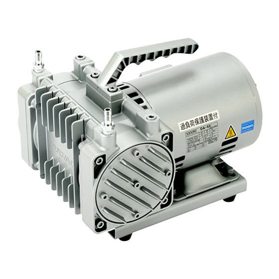
DA-30D,DA-60S
Prior to use
For safe and efficient use of this pump, please read this
manual carefully before operation.
After reading the manual, keep it in your file for future
reference.
Specifications in this manual are subject to change without
notice due to future improvement.
ULVAC KIKO. Inc.
Advertisement
Table of Contents

Related Manuals for Ulvac DA-30D


Summary of Contents for Ulvac DA-30D
- Page 1 For safe and efficient use of this pump, please read this manual carefully before operation. After reading the manual, keep it in your file for future reference. Specifications in this manual are subject to change without notice due to future improvement. ULVAC KIKO. Inc.
-
Page 2: Table Of Contents
Contents Pages with a shaded background are those, which contain items related to safety. …………………………………….01 Before Using the Equipment …………………………………….02 Checks When Opening Packaging …………………………………….03 Using the Pump Safely …………………………………….03 ・ Safety icons …………………………………….04 ・ Cautions for Safety in Use ……………………………………..1 1. - Page 3 Figures and Tables ……………………………………..2 Fig.1 DA-30D Dimensions ……………………………………..2 Fig.2 DA-60S Dimensions Fig.3 Change region of the voltage and frequency……………………………………..4 ………………...5 Fig.4 Example of Piping Used When Evacuating a Vessel ……………………………………..1 Table 1 Product Specifications ……………………………………..6 Table 2 Protector Specifications ……………………………………..8...
-
Page 4: Before Using The Equipment
Before Using the Equipment Thank you for purchasing this product. Your custom is very much appreciated. This pump is designed solely for vacuum discharge, and may malfunction or cause accidents if not handled appropriately. Read the manual thoroughly, and pay due attention to inspections, maintenance, and safety. -
Page 5: Checks When Opening Packaging
Checks When Opening Packaging Check the following after opening the packaging. (1) Is the product as you requested? (2) Are the accessories and necessary parts included? Standard accessories ・User’s manual -------------------- ×1 ・Inlet and outlet caps (fitted to inlet and outlet) -------------------- ×2 〈In case motor specification is 100V〉... -
Page 6: Using The Pump Safely
Using the Pump Safely To ensure that the pump is handled correctly, read this section thoroughly before use. This manual and the warning labels on the pump include safety icons as an aid to understanding safety requirements. These safety icons warn the operator and others of possible dangers and damage and should always be followed. -
Page 7: Cautions For Safety In Use
・Cautions for Safety in Use Danger Applications (1) This pump is not designed to be explosion-proof, and should therefore not be used to discharge explosive gases. (2) In addition to discharge of gas via the outlet, gas may also leak from other parts of the pump, and it should therefore not be used with toxic gases. - Page 8 Warning Power Supply (15) It will cause a serious damage or movement failure to the motor in case of impressing the inverter controlled pressure is given towards the motor itself. Please carefully be noted and do not take the above action. Operation (16) This pump is not designed to be explosion-proof.
- Page 9 Caution Installation The fine clearances used in this pump require that the following conditions be satisfied during storage, installation, and operation. Ambient temperature of 7~40°C and maximum relative humidity of 85% during operation. Equal to or less than meters above the sea level 1000m storage and operation. Other conditions for storage and operation.
- Page 10 Note Installation The pump may malfunction if it is subjected to shocks or tipped over on its side. Do not place objects on, or stand on, the pump. A malfunction may result if the pump is handled in this manner. (3) Float the pump from the system using a rubber shock absorber;...
-
Page 11: Product Outline
(3) Ensure that the gas entering the pump does not contain rubbish, dust, or water (except steam). Note (4) Do not operate the pump for long periods at near-atmospheric pressure. 1.2 Specifications Table 1 Product Specifications Model DA-30D DA-60S 50Hz Pumping 30 L/min 60 L/min Speed 60Hz... -
Page 12: Dimensions
2. Dimensions Fig.1 DA-30D Dimensions Fig.2 DA-60S Dimensions... -
Page 13: Installation And Storage
3. Installation and Storage 3.1 Cautions for Installation and Storage See Warning Warning (1)(2)(3)(5)(7)(9)(10)(11)(12)(13)(15)(16), P04,05 Caution See Caution (1)(2)(3), P06 Note See Note (1)(2)(3)(4), P07 3.2 Environmental Conditions for Installation, Storage, and Operation The fine clearances used in this pump require that the following conditions be satisfied during storage, installation, and operation. -
Page 14: Fluctuations In The Power Voltage And Frequency
3.5 Fluctuations in the power voltage and frequency Standard: Rotation electricity machine general rules JIS C 4034-1:1999,JEC-2137-2000 To the voltage change and frequency change in Domain A, in main rated values, it operates continuously, and can be used practically convenient, and to the voltage change and frequency change in Domain B, it shall operate with main rated values and shall be used practically convenient. -
Page 15: Checking Operation After Installation
3.6 Checking Operation After Installation 1) Remove the rubber caps from the inlet and outlet. 2) Check that the pump switch is OFF, and insert the plug into the 100 V wall socket. Note: Ensure that the power plug is sufficient for the rated voltage and current. 3) Turn the switch ON and check that gas is being drawn into the inlet. -
Page 16: Operation Of The Thermal Protection Relay
4.2 Operation of the Thermal Protection Relay 1) When the thermal protection relay operates, switch the pump power supply OFF, remove the power cord from the outlet, and contact the manufacturer. Note that the pump will be very hot and should not be touched. -
Page 17: Evacuation Rate
5.2 Evacuation Rate The maximum rate of evacuation is reached when air is introduced, and decreases slightly as pressure is reduced. The resistance of the piping system increases with small bore piping which extends over long distances, and this reduces the rate of evacuation. The declared rate of evacuation for this pump is the maximum value achieved with dry air. -
Page 18: Replacing And Cleaning Consumables
Table.3 Consumables List Components Quantity Material Average life Diaphragms Synthetic rubber (NBR) 6,000~8,000hr Air filters Urethane 6,000~8,000hr Head gaskets Synthetic rubber (NBR) 6,000~8,000hr Suction / Exhaust valves 6,000~8,000hr ― Bearing 1set 15,000hr Suction valves 2 [4] Synthetic rubber (NBR) 6,000~8,000hr [ ] : For DA-60S Note that the average life for a component varies with the conditions of use. - Page 19 In the replacement procedure, the terms “primary side” and “secondary side” shall be used to refer to specific locations. Refer to the terms and diagram below when performing the replacement. Exhaust tube (rear) Suction Suction Exhaust tube tube tube DA-60S DA-30D...
- Page 20 i. Parts Removal *First unplug the pump’s power cable from the main power supply. Step 1: Remove (1) the hex socket bolts (M6×25) × Qty.4, and then remove (2) the pump head. Do the same on the opposing pump head. Step 2: First, remove (1) the small flat head screws (M5×12) ×...
- Page 21 Step 4: Remove (1) the hex socket bolts (M5×12) × Qty.4, and then remove (2) the front cover. There are no replacement parts, but during assembly, use it for adjusting the connecting rod position. This step completes the parts removal procedure. The next section is the assembly.
- Page 22 Step 6: Attach the filters at the position shown in the picture on the left. The position is the same for both the primary side and the secondary side. Filter Step 7: Put a new head gasket on the position shown in the Direction of exhaust/suction outlet picture on the left to replace the old one removed in Step 3.
- Page 23 Step 9: Attach the diaphragm. Place the diaphragm on the connection rod, and then adjust its position so that the spacing between the diaphragm, the casing and the connecting rod are even. Step 10: After adjusting the position of the diaphragm, place the push plate for the diaphragm on its top, then fasten them with the small flat head screws (M5×12) ×...
- Page 24 Attachment direction of pump head Step 11: Attach the pump head. First before attaching the pump head, rotate the eccentric shaft to make sure it is in the same position as shown in the picture. The picture shows the attachment of the pump head on the secondary side.
-
Page 25: Troubleshooting List
6.5 Troubleshooting List Table.5 Troubleshooting List Problem Causes Solutions Reference (1) Not connected to power supply. (1) Connect power supply. (2) Switch is OFF. (2) Set switch to 0N. (3) Problem with power supply voltage. (3) Ensure that voltage variation is within +/-10%. (4) Problem with pump wiring. -
Page 26: In Conclusion
7. In Conclusion Please contact the manufacturer’s sales division if you have any questions. Warranty (1) The warranty for this pump (this equipment) extends for a period of one year from the date of shipment. (2) Any malfunctions or defects which occur under normal usage conditions during the warranty period will be repaired free of charge. -
Page 27: Usage Status Check Sheet
Usage Status Check Sheet (for use in Instruction Manual) * For the purpose of safety control of repair personnel, fill in within the heavy line frame and attach the sheet to the item of which repair is requested. * In case this sheet were not attached or filled in, your request of repair and service may not be accepted. - Page 28 株式会社アルバック 規格品事業部 東日本営業部 〒253-8543 神奈川県茅ヶ崎市萩園2500 TEL:0467-89-2416 株式会社アルバック 規格品事業部 西日本営業部 〒532-0003 大阪府大阪市淀川区宮原3-3-31 上村ニッセイビル5F TEL:06-6397-2286 ULVAC KIKO,Inc. https://ulvac-kiko.com/en Please contact us for products, Service Base or other Inquiries from here. https://showcase.ulvac.co.jp/en/ ULVAC,Inc. Components Division 2500 Hagisono, Chigasaki, Kanagawa, 253-8543, Japan TEL:+81-467-89-2261...
Need help?
Do you have a question about the DA-30D and is the answer not in the manual?
Questions and answers