Table of Contents
Advertisement
Quick Links
No.27500-2-01-7
Instruction Manual
Diaphragm Type Dry
Vacuum Pump
DA-41D, DA-81S
DA-41DK, DA-81SK
Indoor specification
Request
Please read this Instruction Manual before starting the pump in order to
use the pump effectively and safely. Please keep this Instruction Manual
carefully.
We reserve our right to change dimensions or specifications of the
motors described in this Instruction Manual for improvement of the
performance without prior notice.
ULVAC KIKO Inc.
Advertisement
Table of Contents

Related Manuals for Ulvac DA-41D


Summary of Contents for Ulvac DA-41D
- Page 1 No.27500-2-01-7 Instruction Manual Diaphragm Type Dry Vacuum Pump DA-41D, DA-81S DA-41DK, DA-81SK Indoor specification Request Please read this Instruction Manual before starting the pump in order to use the pump effectively and safely. Please keep this Instruction Manual carefully. We reserve our right to change dimensions or specifications of the motors described in this Instruction Manual for improvement of the performance without prior notice.
-
Page 2: Table Of Contents
CONTENTS Before use ············································································································ 01 Confirmation in unpacking ························································································ 02 Directions to use safely···························································································· 03 Safety logotypes ···································································································· 03 Precautions about safety in operation ········································································· 04 1. Outline of Equipment ····························································································· 1 1-1. Intended Use and Prohibitions of Equipment ·························································· 1 1-2. - Page 3 Table 1 -1 Equipment Specifications ············································································ 1 Table 6 -1 Consumable Parts List ·············································································· 10 Table 6 -2 Inspection Positions and Guideline of Parts Replacement ································ 11 Table 6 -3 DA-41D(K),DA-81S(K) major parts material Indication ····································· 22 Table 6 -4 Trouble Check List ··················································································· 23...
-
Page 4: Before Use
After reading, store this Instruction Manual on the location where available for reading by operators. Prohibited copying of Instruction Manual Any portion of this Instruction Manual cannot be copied for use by the third party without ULVAC's consent. Observance of laws and ordinances When disposing this pump, please handle by observing laws and the regulations that the local government established. -
Page 5: Confirmation In Unpacking
Whether loosen external screws or inlet-exhaust pipe. Whether coming off positions are found. In case there is trouble by any chance, please contact vendor or ULVAC Sales Department. ATTENTION Do not hold or push the tube at the top of the pump while removing it from the packaging. -
Page 6: Directions To Use Safely
Directions to use safely Please read this "Directions to use safely" before start using the pump and operate the pump correctly. Safety logotype is enumerated in this Instruction Manual and alarm indication on the pump so that operators may understand the items to be observed. Safety logotype is prepared to use the pump correctly and safely and to prevent injury and damage of operators, etc. -
Page 7: Precautions About Safety In Operation
Please pay attention during maintenance work. <Maintenance / repair> When requesting ULVAC overhaul, fill the type of suction gas in "Usage Status Check Sheet" provided at the end of this Instruction Manual. In case the pump is used for exhaust of toxic gas by any chance, internal pump unit is polluted by the toxic gas. - Page 8 (17) Do not allow other personnel than repair engineers to disassemble or repair the pump. * 1 Repair engineers: Those who are trained by ULVAC technical training. (18) Wear dust mask and gloves when conducting replacement work. A minute abrasive particle suspends in the air, and there is a risk to go into the human body when breathing.
- Page 9 Public Cleaning Law ". Never conduce burnout disposal. (10) When the pump failed to operate or abnormal, turn off the power supply to the pump (push switch to ○ side) and disconnect power cable. Contact the vendor or ULVAC for inspection / repair immediately.
- Page 10 In case there is possibility to such trash and dust, mount filters at inlet port to remove them to protect a pump (9) Corrosion-resistant plastic is used in the external covering of the DA-41D, DA-81S however it is not resistant to all chemicals.
-
Page 11: Outline Of Equipment
CAUTION (4) Although corrosion resistance resin for external packaging of DA-41D, DA-81S partly, there are chemicals that erode the corrosion resistance. Prevent splashing the following chemicals on the pump. It is recommended to wipe off chemicals attached regardless description in the followings. -
Page 12: Protector (Thermal Protector)
1-3. Protector (thermal protector) 1) A autoreset type thermal protector for overload protection is built in this pump. This protector prevents motor burnout trouble by shutting the power supply to the motor automatically when rotation stops during operation due to pump failure or current supplied to the motor exceeded due to overload. -
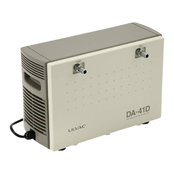
Page 13: Appearance
2. Appearance Fig. 2 -1 DA-41D, DA-81S Appearance Fig. 2 -2 DA-41DK, DA-81SK Appearance Symbols on Symbols on Model No. Dimensions Model No. Dimensions drawing drawing 217mm 202mm DA-41D,81S DA-41DK,81SK (8.5”) (8”) 336.5mm 288mm DA-41D,81S DA-41DK,81SK (11.3”) (13.2”) 157mm 140mm... -
Page 14: Installation / Storage
3. Installation / Storage 3-1. Precautions in Installation / Storage See "Warning" (1) (2) (3) (5) (6) (7) (8) (9) (10) (11) (12) (13) on P. 04. WARNING See "Caution"(1) (2) (3) on P. 05. CAUTION See "Attention" (1) (2) (7) on P. 06.07. ATTENTION 3-2 Installation / Storage and Ambient Condition during Operation This pump is a machine having precise clearance. -
Page 15: Verification Run In Installation
3-4 Verification Run in Installation 1) Detach rubber screen that attached to the inlet / exhaust pipe. 2) Confirm that the pump switch is set to OFF (pushed to ○ side) and connect it to power source. Please use the three core power supply cable (lead wire size 0.75mm or more) as the extension cable, if necessary. -
Page 16: Caution In Operation
4-2 When Thermal Protector Operated 1) When a thermal protector operated, at first turn off the pump power supply (push to ○ side) and disconnect power cable. Contact ULVAC or local agent. Temperature of the pump is very high at this time. -
Page 17: Starting In Cold Ambient
4-3 Starting in Cold Ambient In the cold ambient, there is a case to confront with difficulty in start because of hardened grease and diaphragm of the bearing. When it is difficult to start, follow the procedure described below. 1) Open the inlet port to atmosphere and repeat switch ON, OFF two or three times until the pump starts. -
Page 18: Pump Performance
"Ultimate Pressure" mentioned in Catalog and this Instruction Manual means "the lowest pressure obtained by a pump in the status that no gas is filled from the pump inlet port (idling operation status)”. Ulvac is measuring the pressure by connecting a film-type (diaphragm type) vacuum gauge to inlet port of the pump. -
Page 19: Maintenance・Inspection・Repair
ATTENTION Maintenance / repair range that allowed to perform by repair engineers in the Customers are the following 4 items. Do not conduct the other repair and remodeling other than Ulvac standard option. 1) Replacement of diaphragms 2) Replacement of valves... -
Page 20: Periodic Inspection
Conduct periodic inspections of consumable parts in every 4,500 hours after started using and replace parts according to "Guideline of Parts Replacement". Replacement method [6-4. refer to replacement of consumable part]. In case there is no repair engineer, Ulvac Service Section shall be happy to replace the parts. -
Page 21: Replacement Of Consumable Parts
Wear gloves when replacing diaphragms and valves always. There is a risk of injury. Prepare the following tools and refer to drawing when working replacement. When having difficulty in preparing the tools, ask Ulvac Service Section. 1 Phillips screwdriver: No. 2 2 Hexagonal wrench: (1) Opposite sides 4 mm (2) Opposite sides 5 mm 3 Torque wrench: (1) Hexagon socket of opposite side 4 mm , set tightening torque to 5N∙m... -
Page 22: Replacement Of Diaphragm
Wear gloves when mounting or replacing diaphragms always. There is a risk of injury. CAUTION Use tool No. 1, 2, 3, 4, 5, 6, 7, and 8 1) -1 In case of DA-41D, 81S (* Used DA-81S for reference Photo) Truss head Truss head Front Panel... - Page 23 Bottom dead Diaphragm Top dead center center Hexagon socket head cap screw (M6 x 25) Photo 7 Photo 8 Photo 9 Detach the diaphragm from the main unit. The edge of the diaphragm at the top dead center position (circumference portion) can be grabbed. When one diaphragm is pushed down (bottom dead center), another diaphragm comes up (top dead center).
- Page 24 CAUTION (16) Raise the pump and mount the inlet / exhaust pipe. (Photo 1) 1) - 2.In case of DA-41DK, 81SK * Replace the diaphragm according to the procedure for 1)-1 DA-41D, 81S (4) to (13).
-
Page 25: Replacement Of Valves
No adhesive / screws are used for mounting the valve plate. Valve plate can be detached easily by hands since the valve plate is simply embedded in a circular form groove. (Photo 15) Valve plates of 2 pcs. each DA-41D (K) and 81S (K) are embedded. Valve A Valve B... - Page 26 Detach used valves. (Photo 16) Clean the pump head and the valve retainer with solvent. When clean pump heads, clean both faces of the valve surface side and diaphragm side.
- Page 27 Valve mounting order of DA-41D, DA-41DK Valve mounting order of DA-81S, DA-81SK Secondary side First side Secondary side First side Valve mounting (1): Mount valve A to the position shown by the above Photo one by one. (mount to arrow position)
- Page 28 ● Tighten several times in diagonal / even 5 N · m tightening torque. CAUTION DA-41D (81S) Mount inlet / exhaust pipe, front panel, and top panel. * Procedure is the same as (14) to (16) of 1) replacement of Diaphragm.
-
Page 29: Replacement Of Inlet / Exhaust Filter
3) Replacement of inlet / exhaust filter (It is recommended to replace at the same time when replacing diaphragms.) Use tool No. 1, 2, 3, 4, 6 and 7 DA-41D (K), 81S (K) common procedure (DA-41D (K) filter mounting portion) (DA-81S (K) filter mounting portion) Photo 18 Remove valve retainer from the pump head. -
Page 30: Replacement Of O Ring
Disassemble inlet / exhaust pipe from valve retainer and remove O ring (P-10A) ● Although Inlet / exhaust pipe are different for DA-41D (K) and DA-81S (K), O rings used (P-10A) are same. (Photo 20) ● O rings can be removed by hands. In case a tool is... -
Page 31: Replacement Of Bearing
● Referring the above disassembly process, parts to mount and quantities shall be accurate. CAUTION Mount each part. Procedure is the same as (7) to (8) of 2) replacement of valves. 5) Replacement of bearing Request Ulvac Service Section. -
Page 32: 41D(K), 81S(K) Major Parts Material Indication
6-5 DA-41D (K), 81S (K) Major Parts Material Indication Table 6-3 DA-41D(K)、81S(K) Material Indication Table DA-41D、81S DA-41DK、81SK № № Part Name Material Part Name Material Casing Casing Pump head Pump head Connecting lod Connecting lod Eccentric axis S45C Eccentric axis... -
Page 33: 6-6Trouble Check List
6-6 Trouble Check List Table 6 -4 Trouble Check List Trouble Cause How to resolve problem Ref. contents (1) Not connected to power supply (1) Connected to power supply (2) Switch is not turned ON (2) Push switch to | side (3) Adjust voltage fluctuation to lower than (3) Abnormal voltage of power source input ±10%... - Page 34 Trouble Cause How to resolve problem Ref. contents (1) Performing continuous operation in the (1) Do not conduct continuous operation in Temperature of status that absorption gas pressure is high vicinity of atmospheric pressure pump surface is (2) Mount refrigerating machine such as gas (2) Absorption gas is high temperature abnormally high air conditioners at inlet...
-
Page 35: Conclusion
7. Conclusion In case you have questions, please feel free to contact ULVAC Sales Department. Warranty (1) The warranty for this pump (this equipment) extends for a period of one year from the date of shipment. (2) Any malfunctions or defects which occur under normal usage conditions during the warranty period will be repaired free of charge. -
Page 36: Usage Status Check Sheet (For Use In Instruction Manual)
Usage Status Check Sheet (for use in Instruction Manual) * For the purpose of safety control of repair personnel, fill in within the heavy line frame and attach the sheet to the item of which repair is requested. * In case this sheet were not attached or filled in, your request of repair and service may not be accepted. - Page 37 株式会社アルバック 規格品事業部 東日本営業部 〒253-8543 神奈川県茅ヶ崎市萩園2500 TEL:0467-89-2416 株式会社アルバック 規格品事業部 西日本営業部 〒532-0003 大阪府大阪市淀川区宮原3-3-31 上村ニッセイビル5F TEL:06-6397-2286 ULVAC KIKO,Inc. https://ulvac-kiko.com/en Please contact us for products, Service Base or other Inquiries from here. https://showcase.ulvac.co.jp/en/ ULVAC,Inc. Components Division 2500 Hagisono, Chigasaki, Kanagawa, 253-8543, Japan TEL:+81-467-89-2261...
Need help?
Do you have a question about the DA-41D and is the answer not in the manual?
Questions and answers