Table of Contents
Advertisement
INSTRUCTION MANUAL
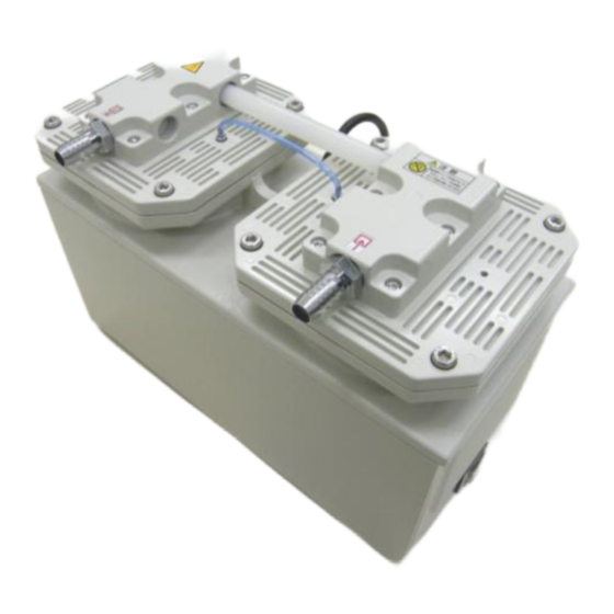
Diaphragm-type Dry Vacuum Pump
DA-121DC、121DD、121DE、121DF
DA-241SC、241SD、241SE、241SF
(According to CE, UKCA, TUV, cTUVus)
DA-121D series
Please read this manual thoroughly to ensure safe and
effective use of the equipment.
Keep this manual in a safe place.
Due to periodic improvements in performance, the
equipment described in this manual is subject to
changes in dimensions and specifications without prior
notice.
Model
Request to Users
ULVAC KIKO,Inc.
No.26700-2-06-8
Original instructions
DA-241S series
Advertisement
Table of Contents

Related Manuals for Ulvac DA-121D Series


Summary of Contents for Ulvac DA-121D Series
- Page 1 Model DA-121DC、121DD、121DE、121DF DA-241SC、241SD、241SE、241SF (According to CE, UKCA, TUV, cTUVus) DA-241S series DA-121D series Request to Users Please read this manual thoroughly to ensure safe and effective use of the equipment. Keep this manual in a safe place. Due to periodic improvements in performance, the...
- Page 2 Declaration of Conformity Company:ULVAC KIKO,Inc. Address:291-7 Chausubaru Saito-city,Miyazaki (ZIP Cord:881-0037) Japan. This declaration is issued under the sole responsibility of the manufacturer. In accordance with the following Directive: 2006/42/EC Machinery Directive 2011/65/EU+(EU)2015/863 RoHS Directive declare under our sole responsibility that the product,...
- Page 3 Declaration of Conformity Company:ULVAC KIKO,Inc. Address:291-7 Chausubaru Saito-city,Miyazaki (ZIP Cord:881-0037) Japan. This declaration is issued under the sole responsibility of the manufacturer. In accordance with the following Directive: Supply of Machinery (Safety) Regulations 2008 (S.I. 2008 No. 1597, as amended by S.I. 2019 No. 696) The Restriction of the Use of Certain Hazardous Substances in Electrical and Electronic Equipment Regulations 2012 (S.I.
-
Page 4: Table Of Contents
3) Replacing DA-121D series Valves ................13 4) Replacing DA-241S series Valves ................14 5) Replacing the DA-121D series outlet filter ..............15 6) Replacing the DA-241S series outlet filter ..............15 7) Replacing DA-121D and DA-241S series O Rings ........... 16... - Page 5 Figures and Tables Fig.2.1 DA-121D series Dimensions ....................2 Fig.2.2 DA-241S series Dimensions....................3 Fig.3.1 Change region of the voltage and frequency ................5 Fig.3.2 Example of Piping Used When Evacuating a Vessel ............... 6 Table 1.1 Product Specifications (50/60 Hz) ..................1...
-
Page 6: Before Using The Equipment
Before Using the Equipment Thank you for purchasing this product. Your custom is very much appreciated. This pump is designed solely for vacuum discharge, and may malfunction or cause accidents if not handled appropriately. Read the manual thoroughly, and pay due attention to inspections, maintenance, and safety. -
Page 7: Checks When Opening Packaging
! Caution Do not hold or push the tube at the top of the pump while removing it from the packaging. Damage to the tube may affect performance of the pump. DA-121D DA-241S series series DA-241S series DA-121D series 02... -
Page 8: Using The Pump Safety
Using the Pump Safety To ensure that the pump is handled correctly, read this section thoroughly before use. This manual and the warning labels on the pump include safety icons as an aid to understanding safety requirements. These safety icons warn the operator and others of possible dangers and damage and should always be followed. -
Page 9: Cautions For Safety In Use
・Cautions for Safety in Use Danger Applications (1) This pump is not designed to be explosion-proof, and should therefore not be used to discharge explosive gases. (2) Not be used with toxic gases. In addition to discharge of gas via the outlet, gas may also leak from other parts of the pump, and it should therefore not be used with toxic gases. - Page 10 Warning Operation (12) This pump is not designed to be explosion-proof. When using the pump, ensure that there are no inflammable materials such as solvents, or explosive gases, in the vicinity. Use under such conditions may result in injury or fire. (13) Inserting fingers or objects into the pump inlet may result in electric shock, injury, or fire.
- Page 11 Caution (4) Do not hold or push the tube at the top of the pump (see below). Damage to the tube may affect performance of the pump. DA-121D series DA-241S series Operation (5) Touching rotating components (e.g. motor, main shaft, axial joints, cooling fan) while the pump is in operation may result in injury.
- Page 12 Note Installation (1) The pump may malfunction if it is subjected to shocks or tipped over on its side. Applications (2) This pump is not designed to be corrosion-proof. Use it only with clean air at normal temperature, or with gases of equivalent characteristics. (3) This pump is designed solely for vacuum extraction.
-
Page 13: Product Outline
1. Product Outline 1.1 Purpose of Use and Prohibitions This product is a dry vacuum pump which employs reciprocating motion of a rubber diaphragm for vacuum discharge. Observe the following prohibitions to ensure normal operation of the pump. Prohibitions Warning (1) This pump employs only vacuum operation, and must not be pressurized. -
Page 14: Dimensions
Warning See Warning (8), P04 Caution See Caution (6), P06 2. Dimensions Fig.2.1 DA-121D series Dimensions 2... - Page 15 Fig.2.2 DA-241S series Dimensions 3...
-
Page 16: Installation And Storage
3. Installation and Storage 3.1 Cautions for Installation and Storage Warning See Warning (1)(2)(3)(5)(6)(7)(8)(9)(10)(11), P04 Caution See Caution (1)(2)(3), P05 (4),P06 Note See Note (1), P07 3.2 Environmental Conditions for Installation, Storage, and Operation The fine clearances used in this pump require that the following conditions be satisfied during storage, installation, and operation. -
Page 17: Checking Operation After Installation
Fig. 3.1 Change region of the voltage and frequency 3.6 Checking Operation After Installation 1) Remove the rubber caps from the inlet and outlet. 2) Check that the pump switch is OFF (set to O), and connect the power supply. Note: Ensure that the power cord is sufficient for the rated voltage and current. -
Page 18: Piping
3.7 Piping 1) Install piping carefully to prevent leaks. 2) Piping connected to the inlet should be at least 12 mm inside diameter. 3) Ensure that piping connected to the outlet does not cause back pressure. Maximum back pressure is 0.03 MPa (gauge pressure). 4) In case of selecting the inlet pipe and exhaust pipe that are not from our products, please select the exhaust pipe that has same or larger inner diameter length with the inlet pipe. -
Page 19: Cautions For Operation
4. Cautions for Operation 4.1 Cautions for Operation Danger See Danger (1)(2), P04 Warning See Warning (8), P04 (12)(13)(14), P05 Caution See Caution (5)(7)(8), P06 Note See Note (2)(3)(4)(5)(6)(7)(8)(9), P07 4.2 Operation of the Thermal Protector 1) When the thermal protector operates, switch the pump power supply OFF (set to O), remove the power cord from the outlet, and contact the manufacturer. -
Page 20: Pump Performance
5. Pump Performance 5.1 Pressure Achieved The term “pressure achieved” as employed in the catalogue and in this manual is defined as “the minimum pressure obtained by the pump without introduction of gas from the pump inlet . Note that the indicator values for pressure may differ between types of vacuum gauges. Pressure achieved in practice, occasionally becomes higher than that noted in the catalogue for the following reasons. -
Page 21: Maintenance, Inspection, And Repair
6. Maintenance, Inspection, and Repair 6.1. Cautions for Maintenance, Inspection, and Repair Danger See Danger (3), P04 Warning See Warning (4) , P04 (15)(16), P05 Caution See Caution (9)(10), P06 Note See Note (10), P07 Maintenance and repair by the customer’s repair technician is limited to the following procedures. - Page 22 <Consumables List> Table 6.1 Consumables List(DA-121D,241S series) Quantity Components Material Average life 121D 241S ――― Inlet Filter Stainless steel Outlet Filter Urethane 6000 h Synthetic rubber Diaphragms 6000 h (EPDM) A valve PTFE 6000 h C valve PTFE 6000 h B valve Retainer 6000 h A valve Retainer...
-
Page 23: Replacing And Cleaning Consumables
7. Dust Mask and Gloves ※ Use tool Nos. 5 and 6 to wipe areas contaminated while replacing components. 1) Cleaning DA-121D series and DA-241S series Inlet Filters It is recommended that diaphragms, valves, and O rings be cleaned when they are replaced. - Page 24 2) Replacing DA-121D series and DA-241S series Diaphragms It is recommended that both diaphragms be replaced simultaneously. Use tools 1, 2, 4, 5, 6 and 7 listed above. (Note: Always wear gloves.) Stage 2 Stage 1 M8×25 Photo 1 Photo 2 (1) Remove the eight M8×25 hex socket head screws shown in Photo 1.
- Page 25 3) Replacing DA-121D Valves It is recommended that these valves be replaced at the same time as the diaphragms. Use tools 1, 2, 5, and 6 listed above. (1) Remove the stage 1 and stage 2 pump heads as described in 2) Replacing DA-121D and DA-241S Diaphragms, step (1).
-
Page 26: Replacing Da-241S Series Valves
Note: Check that the O ring is flattened to the extent that it is no longer visible when viewed from the side. (5) Fit the pump head to the pump while referring to 2) Replacing DA-121D series and DA-241S series Diaphragms. -
Page 27: Replacing The Da-121D Series Outlet Filter
(Photos 11-1, 11-2) Outlet filter Photo 11-1 Photo 11-2 6) Replacing the DA-241S series outlet filter (Use tool 1,5) ① Use 5) Replacing the DA-121D series outlet filter to replace the stage 1 outlet filter. (Photo 12) Outlet filter Photo 12 15... -
Page 28: Replacing Da-121D And Da-241S Series O Rings
7) Replacing DA-121D and DA-241S O Rings It is recommended that these O rings be replaced at the same time as the diaphragms. Use tools 1, 2, 3, 4, 5, and 6 listed above. (1) Remove the valve retainers as described in 3) Replacing DA-121D Valves, steps (1)~(2). P-48 O rings P-48 O rings P-18 O rings... -
Page 29: Troubleshooting List
6.5 Troubleshooting List Table 6.3 Troubleshooting List Problem Causes Solutions Reference (1) Not connected to power supply. (1) Connect power supply. (2) Switch is OFF. (2) Set switch to I. (3) Problem with power supply voltage. (3) Ensure that voltage variation is within +/-10%. -
Page 30: In Conclusion
7. In Conclusion Please contact the manufacturer’s sales division if you have any questions. Warranty (1) The warranty for this pump (this equipment) extends for a period of one year from the date of shipment. (2) Any malfunctions or defects which occur under normal usage conditions during the warranty period will be repaired free of charge. -
Page 31: Usage Status Check Sheet
Usage Status Check Sheet (for use in Instruction Manual) * For the purpose of safety control of repair personnel, fill in within the heavy line frame and attach the sheet to the item of which repair is requested. * In case this sheet were not attached or filled in, your request of repair and service may not be accepted. - Page 32 株式会社アルバック 規格品事業部 東日本営業部 〒253-8543 神奈川県茅ヶ崎市萩園2500 TEL:0467-89-2416 株式会社アルバック 規格品事業部 西日本営業部 〒532-0003 大阪府大阪市淀川区宮原3-3-31 上村ニッセイビル5F TEL:06-6397-2286 ULVAC KIKO,Inc. https://ulvac-kiko.com/en Please contact us for products, Service Base or other Inquiries from here. https://showcase.ulvac.co.jp/en/ ULVAC,Inc. Components Division 2500 Hagisono, Chigasaki, Kanagawa, 253-8543, Japan TEL:+81-467-89-2261...
Need help?
Do you have a question about the DA-121D Series and is the answer not in the manual?
Questions and answers