Table of Contents
Advertisement
Quick Links
No. 20D00-2-01-3
Original instructions
INSTRUCTION MANUAL
Oscillating Piston Dry Vacuum Pump
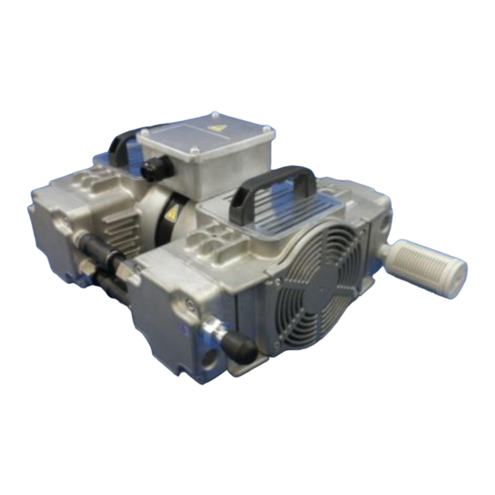
DOP-301SB/SVB
DOP-301SB
DOP-301SVB
Request to Users
Please read this manual thoroughly to ensure safe and
effective use of the equipment.
Keep this manual in a safe place.
Due to periodic improvements in performance, the
equipment described in this manual is subject to changes
in dimensions and specifications without prior notice.
ULVAC KIKO, Inc.
Advertisement
Table of Contents

Related Manuals for Ulvac DOP-301SB


Summary of Contents for Ulvac DOP-301SB
- Page 1 Please read this manual thoroughly to ensure safe and effective use of the equipment. Keep this manual in a safe place. Due to periodic improvements in performance, the equipment described in this manual is subject to changes in dimensions and specifications without prior notice. ULVAC KIKO, Inc.
- Page 2 Declaration of Conformity Company:ULVAC KIKO,Inc. Address:291-7 Chausubaru Saito-city,Miyazaki (ZIP Cord:881-0037) Japan. This declaration is issued under the sole responsibility of the manufacturer. In accordance with the following Directive: 2006/42/EC Machinery Directive 2011/65/EU+(EU)2015/863 RoHS Directive declare under our sole responsibility that the product,...
- Page 3 Declaration of Conformity Company:ULVAC KIKO,Inc. Address:291-7 Chausubaru Saito-city,Miyazaki (ZIP Cord:881-0037) Japan. This declaration is issued under the sole responsibility of the manufacturer. In accordance with the following Directive: Supply of Machinery (Safety) Regulations 2008 (S.I. 2008 No. 1597, as amended by S.I. 2019 No. 696) The Restriction of the Use of Certain Hazardous Substances in Electrical and Electronic Equipment Regulations 2012 (S.I.
-
Page 4: Table Of Contents
Contents Pages with a shaded background are those which contain items related to safety. 0.Before Using the Equipment ......................01 0.1 Checks When Opening Packaging ..................02 0.2 Using the Pump Safely ......................03 ・ Safety icons ..........................03 ・ Cautions for Safety in Use ...................... - Page 5 (used with requests for disassembly and repair) ・ Product information, service bases, and contact information Figures and Tables Fig. 1.1 DOP-301SB ........................2 Fig. 1.2 DOP-301SVB ........................2 Fig. 3.1 Fluctuations in the power voltage and frequency ............... 5 Fig. 3.2 Example of Piping Used When Evacuating a Vessel ............
-
Page 6: 0.Before Using The Equipment
0.Before Using the Equipment Thank you for purchasing this product. Your custom is very much appreciated. This pump is only for vacuum pumping, and may malfunction or cause accidents if not handled appropriately. Read the manual thoroughly, and pay due attention to inspections, maintenance, and safety. -
Page 7: Checks When Opening Packaging
4. Use ventilation holes, and fit a cooling fan, to reduce the temperature in the vicinity of the pump. Ensure that the pump cooling fan inlet is not blocked. Ensure that a space of at least 100mm is available on all sides of the pump. DOP-301SB DOP-301SVB... -
Page 8: Using The Pump Safely
0.2 Using the Pump Safely To ensure that the pump is handled correctly, read this section thoroughly before use. This manual and the warning labels on the pump include safety icons as an aid to understanding safety requirements. These safety icons warn the operator and others of possible dangers and damage and should always be followed. -
Page 9: Cautions For Safety In Use
・Cautions for Safety in Use Danger Applications (1) This pump is not designed to be explosion-proof, and should therefore not be used to evacuate explosive gases. (2) In addition to discharge of gas via the pump outlet, gas may leak from the pump itself. Use it only with clean air at normal temperature, or gases of equivalent characteristics. - Page 10 Warning Power Supply (10)When attaching the main power cord to the pump, please use the power cord which meets the rated voltage and current, pursuant to the provision. 4-Core-cable(Size of the wire lead: 1.0mm or larger, 300V or more, 10A or more, 100°C or higher, one earth cable included) Ensure that one of the core wires is used as an earth wire.
- Page 11 Caution Installation (1) To prevent back injuries, always use at least two people when lifting and moving the pump. (2) Microscopic particles resulting from wear of components are discharged from the outlet and contaminate the room. If necessary, connect a pipe from the discharge outlet to the outside of the building.
- Page 12 Caution Maintenance and Repair (9) If the pump ceases operation, switch off the main power supply immediately to prevent accidents, remove the power cord from the wall outlet, and contact your dealer or the manufacturer for inspection and repair. (10)After stopping the pump, leave it for 30 minutes or more and begin work on it only after checking that it has cooled sufficiently.
-
Page 13: Product Outline
(4) Do not attempt to evacuate gases containing particles, dust, water, or corrosive gases. (5) Do not operate the pump for long periods at near-atmospheric pressure. 1.2 Specifications Table 1.1 Product Specifications (50Hz/60Hz) Model DOP-301SB DOP-301SVB Evacuate rate (L/min) 300/330 Pressure achieved (kPa) 3φ... -
Page 14: Thermal Protector
2) Always fit other protective devices (eg earth leakage breaker, motor breaker) in addition to the overload protection relay. Warning See "Warning" (8) on p.04. Caution See "Caution" (6) on p.06. 2. Dimensions Fig. 1-1 DOP-301SB... -
Page 15: Installation And Storage
Fig.1-2 DOP-301SVB 3. Installation and Storage 3.1 Cautions for Installation and Storage See "Warning" (1), (2), (3), (5), (6), (7), (8), (9), (10), (11), (12) and (13) on p.04 Warning and 05. See "Caution" (1), (2) (3) and (4) on Caution p.06. -
Page 16: Environmental Conditions For Installation, Storage, And Operation
3.2 Environmental Conditions for Installation, Storage, and Operation The fine clearances used in this pump require that the following conditions be satisfied during storage, installation, and operation. (1) Ambient temperature of 0~40°C and maximum relative humidity of 85% during operation. (2) Other conditions (during storage and operation) a) Level floor of sufficient strength b) No condensation... -
Page 17: Fluctuations In The Power Voltage And Frequency
3.5 Fluctuations in the power voltage and frequency Standard: Rotation electricity machine general rules IEC60034-1:2004 To the voltage change and frequency change in Domain A, in main rated values, it operates continuously, and can be used practically convenient, and to the voltage change and frequency change in Domain B, it shall operate with main rated values and shall be used practically convenient. -
Page 18: Cautions For Operation
4. Cautions for Operation 4.1 Cautions for Operation Danger See "Danger" (1) and (2) on p.04. See "Warning"(8), (14), (15) and (16) Warning on p.04 and p.05. See "Caution" (4), (5), (7) and (8) on Caution p.06. See "Note" (3), (4), (5), (6) and (7) on Note p.07. -
Page 19: Evacuation Rate
(1) The fact that the vacuum gauge is mounted a distance from the pump, the steam generated by water droplets and rust etc on the inside walls of the pump and piping, and a variety of gases present in the system result in increased pressure. (2) Leaks into the vacuum system introduce other gases, resulting in increased pressure. -
Page 20: Cautions For Maintenance, Inspection, And Repair
“Guidelines for Replacement and Cleaning "on the following page. Refer to 6.4 Replacing Consumables and Cleaning for procedures. Request replacement by the manufacturer’s service division if a repair technician is not available. <Consumables List> Table 6.1 Consumables List (DOP-301SB/301SVB) Components Quantity Material Average life ―――... -
Page 21: Replacing Consumables And Cleaning
< Guidelines for Replacement and Cleaning > Replace or clean components if performance is reduced and/or the following symptoms appear. Backup inlet and outlet valves: Replace in the event of abnormal wear, hardening, or cracking. Cup packing: Replace in the event of abnormal wear, hardening, or cracking. Inlet and outlet valves: Replace in the event of deformation, hardening, or chipping. -
Page 22: Preparations For Replacing The Pump Parta
It is recommended that the consumables for the remaining three heads are also replaced using this procedure. The replacement procedure is described using the DOP-301SB. Remove the angle when replacing consumables in the DOP-301SVB. -
Page 23: Removing The Head Cover
(4) Using the 5 mm hex wrench, loosen the M6X20 hex-headed bolt holding the handle. (5) Remove the handle and panel. (6) Stand the pump up so that the head may be removed vertically. (4), (5) Loosen the bolt. (6) Stand the pump up so that the head may be removed Vertically. -
Page 24: Removing The Cylinder
3) Removing the Cylinder (1) Mark the casing and cylinder with a permanent marker before removing the cylinder. (2) While wearing the gloves, turn the fan slowly upwards. Always ensure that gloves are worn. (3) Remove the cylinder upwards. (1) Mark the casing and cylinder. (2) Turn the fan upwards. -
Page 25: Removing Small Cylinder Components
(3) Remove the holder plate. (4) Remove cup packing. (5) Removal complete. 5) Removing Small Cylinder Components (1) Loosen the outlet valve holder plate M3×L5 roundhead screw. (2) Remove the outlet valve holder plate, backup outlet valve, and outlet valve. (3) Loosen the inlet valve holder plate M3×L5 roundhead screw. - Page 26 (6) Cylinder list a: Inlet valve b: Outlet valve c: Backup outlet valve d: Backup inlet valve a d c b...
-
Page 27: Removing Small Holder Plate Components
6) Removing Small Holder Plate Components (1) Holder plate and cup packing components list e: Inlet valve rubber separator f: Cup packing f e 7) Replacing and Assembling Consumables (1) Replace the cup packing. Place the cup packing on the connecting rod to ensure that the canopy is downwards. - Page 28 (4) Place two inlet valves on the washed cylinder and place the backup inlet valve, inlet valve holder plate on top. Ensure that the inlet valve holder plate is mounted in the correct orientation. The top of the inlet valve holder plate is set facing up so that the shorter direction (distance from the center of the hole to the edge face) is pointing towards the right-hand side of the inlet valve.
- Page 29 (11) Lay the pump on its side and fit the panel and handle. (12) Replacement of consumables is now complete (fit the angle to complete replacing consumables in the DOP-301SB). (7) Inserting the cylinder. (8) Replacing the gasket.
-
Page 30: Troubleshooting List
6.5 Troubleshooting List Table 6.3 Troubleshooting List Problem Causes Solutions Reference (1) Not connected to power supply. (1) Connect power supply. (2) The main power supply switch is not (2) Set switch to I. (3) Problem with power supply voltage. (3) Ensure that voltage variation is within +/-10%. -
Page 31: In Conclusion
7. In Conclusion Please contact the manufacturer’s sales division if you have any questions. Warranty (1) The warranty for this pump (this equipment) extends for a period of one year from the date of shipment. (2) Any malfunctions or defects which occur under normal usage conditions during the warranty period will be repaired free of charge. -
Page 32: Usage Status Check Sheet
Usage Status Check Sheet (for use in Instruction Manual) * For the purpose of safety control of repair personnel, fill in within the heavy line frame and attach the sheet to the item of which repair is requested. * In case this sheet were not attached or filled in, your request of repair and service may not be accepted. - Page 33 株式会社アルバック 規格品事業部 東日本営業部 〒253-8543 神奈川県茅ヶ崎市萩園2500 TEL:0467-89-2416 株式会社アルバック 規格品事業部 西日本営業部 〒532-0003 大阪府大阪市淀川区宮原3-3-31 上村ニッセイビル5F TEL:06-6397-2286 ULVAC KIKO,Inc. https://ulvac-kiko.com/en Please contact us for products, Service Base or other Inquiries from here. https://showcase.ulvac.co.jp/en/ ULVAC,Inc. Components Division 2500 Hagisono, Chigasaki, Kanagawa, 253-8543, Japan TEL:+81-467-89-2261...
Need help?
Do you have a question about the DOP-301SB and is the answer not in the manual?
Questions and answers