Table of Contents
Advertisement
Quick Links
No. 20106-2-01-14
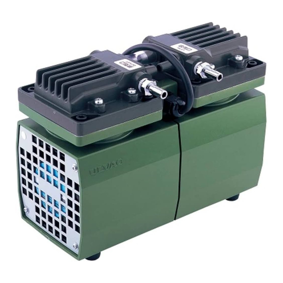
DIAPHRAGM DRY VACUUM PUMP
INSTRUCTION MANUAL
MODEL DA-20D
MODEL DA-40S
Prior to use
For safe and efficient use of this pump, please read this manual
carefully before operation.
After reading the manual, keep it in your file for future reference.
Specifications in this manual are subject to change without notice
due to future improvement.
ULVAC KIKO, Inc.
Advertisement
Table of Contents

Related Manuals for Ulvac DA-20D


Summary of Contents for Ulvac DA-20D
- Page 1 No. 20106-2-01-14 DIAPHRAGM DRY VACUUM PUMP INSTRUCTION MANUAL MODEL DA-20D MODEL DA-40S Prior to use For safe and efficient use of this pump, please read this manual carefully before operation. After reading the manual, keep it in your file for future reference.
-
Page 2: Table Of Contents
Contents Pages with a shaded background are those, which contain items related to safety. Before Using the Equipment ..........01 Checks When Opening Packaging ..........02 Using the Pump Safely ..........03 Safety icons ..........03 Cautions for Safety in Use .......... - Page 3 ..........16 7. In Conclusion ..........17 Warranty ..........17 Usage Status Check Sheet Figures and Tables Fig.1 DA-20D Dimensions ..........2 Fig.2 DA-40S Dimensions ..........2 Fig.3 Attaching Anti-vibration Rubbers ..........4 Fig.4 Screws for Anti-vibration Rubbers ..........4 Fig.5 Change region of the voltage and frequency ........
-
Page 4: Before Using The Equipment
Before Using the Equipment Thank you for purchasing this product. Your custom is very much appreciated. This pump is designed solely for vacuum discharge, and may malfunction or cause accidents if not handled appropriately. Read the manual thoroughly, and pay due attention to inspections, maintenance, and safety. -
Page 5: Checks When Opening Packaging
Checks When Opening Packaging Check the following after opening the packaging. (1) Is the product as you requested? (2) Are the accessories and necessary parts included? Standard accessories ・User’s manual -------------------- ×1 ・Inlet and outlet caps (fitted to inlet and outlet) -------------------- ×2 〈In case motor specification is 100V〉... -
Page 6: Using The Pump Safely
Using the Pump Safely To ensure that the pump is handled correctly, read this section thoroughly before use. This manual and the warning labels on the pump include safety icons as an aid to understanding safety requirements. These safety icons warn the operator and others of possible dangers and damage and should always be followed. - Page 7 Warning Installation (1) Do not use the pump in an explosive atmosphere. Such use may result in injury and fire. (2) Ensure that there are no inflammable materials such as solvents in the vicinity when using the pump. (3) Ensure that the pump is freely ventilated to prevent overheating, which may result in fire or burns.
- Page 8 Caution Installation The fine clearances used in this pump require that the following conditions be satisfied during storage, installation, and operation. 1. Ambient temperature of 7~40°C and maximum relative humidity of 85% during operati 2. Equal to or less than meters above the sea level 1000m storage and operation. 3.
- Page 9 Caution Maintenance and Repair (10) Dispose in accordance with legislation for disposal and cleaning of waste products, handle as industrial waste, and do not incinerate. (11) If the pump ceases operation, turn power OFF (set switch to O) immediately to prevent accidents, remove the power cord from the wall outlet, and contact your dealer or the manufacturer for inspection and repair.
-
Page 10: Product Outline
(3) Ensure that the gas entering the pump does not contain rubbish, dust, or water (except steam). Note (4) Do not operate the pump for long periods at near-atmospheric pressure. 1.2 Specifications Table.1 Specifications Model DA-20D DA-40S PumpingSpeed (50Hz/60Hz) 20/24 L/min 40/46 L/min 5.33×10 19.9 ×10 Ultimate Pressure (*9.33 ×10... -
Page 11: Fig.1 Da-20D Dimensions
2. DIMENSIONAL DRAWING ※・When motor specifications are 115V, 200V, and 220V ,a power cord is three core cable. Plug adapter is not attached. Fig.1 DA-20D Dimensions Fig.2 DA-40S Dimensions... -
Page 12: Cautions For Safety In Use
3. Installation and Storage 3.1 Cautions for Installation and Storage See Warning Warning (1)(2)(3)(5)(6)(7)(8)(9)(10)(11)(12)(13)(15), P04 See Caution (1)(2)(3), P05 Caution Note See Note (1)(2)(3)(4)(8), P06 3.2 Environmental Conditions for Installation, Storage, and Operation The fine clearances used in this pump require that the following conditions be satisfied during storage, installation, and operation. -
Page 13: Electric Wiring
Insertion-type connector Switch Fig.3 Attaching Anti-vibration Rubbers Protrusion into pump 3.5~4mm Fig.4 Screws for Anti-vibration Rubbers 3-4 Electric Wiring (1) The wire diameter of power cord must be φ0.75mm or more. (2) We recommend end-user to equip protection device such as earth leakage breaker motor breaker on electric wiring to prevent from motor burnout which may occur by overcurrent. -
Page 14: Fluctuations In The Power Voltage And Frequency
3.5 Fluctuations in the power voltage and frequency Standard: Rotation electricity machine general rules JIS C 4034-1:1999,JEC-2137-2000 To the voltage change and frequency change in Domain A, in main rated values, it operates continuously, and can be used practically convenient, and to the voltage change and frequency change in Domain B, it shall operate with main rated values and shall be used practically convenient. -
Page 15: Checking Operation After Installation
3.6 Checking Operation After Installation 1) Remove the rubber caps from the inlet and outlet. 2) Check that the pump switch is OFF, and insert the plug into the 100 V wall socket. Note: Ensure that the power plug is sufficient for the rated voltage and current. 3) Turn the switch ON and check that gas is being drawn into the inlet. -
Page 16: Operation Of The Thermal Protector
4.2 Operation of the Thermal Protector 1) When the thermal protector operates, switch the pump power supply OFF, remove the power cord from the outlet, and contact the manufacturer. Note that the pump will be very hot and should not be touched. -
Page 17: Maintenance, Inspection, And Repair
6. Maintenance, Inspection, and Repair 6.1. Cautions for Maintenance, Inspection, and Repair Danger See Danger (3), P03 Warning See Warning (4)(18)(19), P04 Caution See Caution (10)(11)(12)(13), P06 See Note (12), P06 Note Maintenance and repair by the customer’s repair technician is limited to the following procedures. Do not undertake other repairs, or make modifications other than the standard options supplied by the manufacturer. -
Page 18: Replacing And Cleaning Consumables
<Replacement Guide> Replace or clean components if performance is reduced or the following symptoms become apparent. Table.3 Locations for Maintenance and Inspection Period of Method of Inspection item Replacement guidelines operation inspection Deformation, crack and Diaphragm Visual check hardening Suction / exhaust valve Deformation and crack Visual check Hardening, deformation,... - Page 19 In the replacement procedure, the terms “primary side” and “secondary side” shall be used to refer to specific locations. Refer to the terms and diagram below when performing the replacement. Primary side Secondary side Primary side Secondary side Exhaust tube Suction tube Suction tube Exhaust tube DA-20D DA-40S...
- Page 20 i. Parts Removal *First unplug the pump’s power cable from the main power supply. Step 1: Remove (1) the hex socket bolts (M6×18) × Qty.4, and then remove (2) the pump head. Do the same on the opposing pump head. Step 2: First, remove (1) the small flat head screws (M5×10) ×...
- Page 21 ii. Attaching Parts & Assembly Step 4: Attach the diaphragm. Check that the Teflon liner is placed on the circumference of the diaphragm. Teflon liners Step 5: Replace the diaphragm with a new one and place the push plate for the diaphragm on top of it.
- Page 22 Step 6: Attach the air release valve on the suction side. Suction Correct Replace the old air release valve removed in Step 3 with a side position new one. Attach the parts in the order of the air release valve, plain washer and then the small pan head screw (M3×5).
- Page 23 Step 8: Attach the pump head. Please note that the Position of the exhaust valve mounting orientation of the pump head is different for DA-20D and DA-40S. Refer to the pictures on the left to make sure that the pump heads are attached ① ①...
- Page 24 Position of the exhaust suction tube different for DA-20D and DA-40S. Refer to the pictures on the left to make sure that the pump heads are attached correctly. *Pump head covers attached in an incorrect ①...
-
Page 25: Troubleshooting List
Troubleshooting List Table.4 Troubleshooting List Problem Causes Solutions Reference (1) Not connected to power supply. (1) Connect power supply. (2) Switch is OFF. (2) Set switch to I. (3) Ensure that voltage variation is within (3) Problem with power supply voltage. +/-10%. -
Page 26: In Conclusion
7. In Conclusion This manual contains only general information about pump operation. Therefore, if you come up with any question or trouble, contact our representative or ULVAC KIKO. Warranty (1) The warranty for this pump (this equipment) extends for a period of one year from the date of shipment. -
Page 27: Usage Status Check Sheet
Usage Status Check Sheet (for use in Instruction Manual) * For the purpose of safety control of repair personnel, fill in within the heavy line frame and attach the sheet to the item of which repair is requested. * In case this sheet were not attached or filled in, your request of repair and service may not be accepted. - Page 28 株式会社アルバック 規格品事業部 東日本営業部 〒253-8543 神奈川県茅ヶ崎市萩園2500 TEL:0467-89-2416 株式会社アルバック 規格品事業部 西日本営業部 〒532-0003 大阪府大阪市淀川区宮原3-3-31 上村ニッセイビル5F TEL:06-6397-2286 ULVAC KIKO,Inc. https://ulvac-kiko.com/en Please contact us for products, Service Base or other Inquiries from here. https://showcase.ulvac.co.jp/en/ ULVAC,Inc. Components Division 2500 Hagisono, Chigasaki, Kanagawa, 253-8543, Japan TEL:+81-467-89-2261...
Need help?
Do you have a question about the DA-20D and is the answer not in the manual?
Questions and answers