Table of Contents
Advertisement
Quick Links
No.29100-2-03-13
INSTRUCTION MANUAL
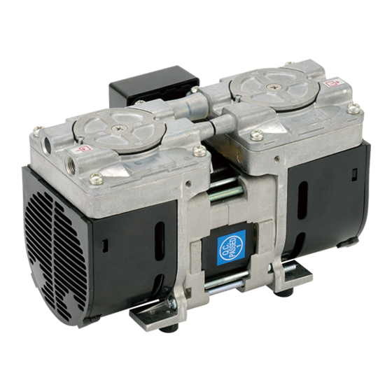
Diaphragm-type Dry Vacuum Pump
Model: DAP-6D, 12S Series
Request to Users
Please read this manual thoroughly to ensure safe
and effective use of the equipment.
Keep this manual in a safe place.
Due to periodic improvements in performance, the
equipment described in this manual is subject to
changes in dimensions and specifications without
prior notice.
ULVAC KIKO, Inc.
Advertisement
Table of Contents

Related Manuals for Ulvac DAP-6D Series


Summary of Contents for Ulvac DAP-6D Series
- Page 1 Please read this manual thoroughly to ensure safe and effective use of the equipment. Keep this manual in a safe place. Due to periodic improvements in performance, the equipment described in this manual is subject to changes in dimensions and specifications without prior notice. ULVAC KIKO, Inc.
-
Page 2: Table Of Contents
Contents Pages with a shaded background are those, which contain items related to safety. 1.Before Using the Equipment ............2. Using the Pump Safely ..............・Safety icons ................2 ・Cautions for Safety in Use ............. 2 3. Product Outline ................4.Dimentional Drawing.............. -
Page 3: Before Using The Equipment
1. Before Using the Equipment Thank you for purchasing this product. Your custom is very much appreciated. This pump is designed solely for vacuum discharge, and may malfunction or cause accidents if not handled appropriately. Read the manual thoroughly, and pay due attention to inspections, maintenance, and safety. -
Page 4: Using The Pump Safely
2. Using the Pump Safely To ensure that the pump is handled correctly, read this section thoroughly before use. This manual and the warning labels on the pump include safety icons as an aid to understanding safety requirements. These safety icons warn the operator and others of possible dangers and damage and should always be followed. - Page 5 Warning Installation (1) Do not use the pump in an explosive atmosphere. Such use may result in injury and fire. (2) Ensure that there are no inflammable materials such as solvents in the vicinity when using the pump. (3) Ensure that the pump is freely ventilated to prevent overheating, which may result in fire or burns.
- Page 6 Warning Operation (15) This pump is not designed to be explosion-proof. When using the pump, ensure that there are no inflammable materials such as solvents, or explosive gases, in the vicinity. Use under such conditions may result in injury or fire. (16) Inserting fingers or objects into the motor inlet may result in electric shock, injury, or fire.
- Page 7 Caution Operation (2) Do not close the outlet while the pump is in operation. (3) Touching rotating components (ex motor, main shaft, axial joints, cooling fan) while the pump is in operation may result in injury. (4) The overload protector operates when the pump becomes excessively hot. Touching it in this condition may result in burns.
- Page 8 Note Operation (7) Ensure that the pump is used within an ambient temperature range of 0 - 40°C. Use at high temperatures will dramatically reduce the life of the pump. Install cooling equipment (e.g. a fan) if the pump is to be used at an ambient temperature in excess of 40°C, and set ambient temperature to 40°C or less.
-
Page 9: Product Outline
3. Product Outline 3.1 Purpose of Use and Prohibitions This product is a dry vacuum pump which employs reciprocating motion of a rubber diaphragm for vacuum discharge. Observe the following prohibitions to ensure normal operation of the pump. Prohibitions Warning (1) This pump employs only vacuum operation, and must not be pressurized. -
Page 10: Dimentional Drawing
4. Dimensional Drawing Motor specifications ※ 200V,220V is attached to Power supply cord without switch and plug Fig.-1 DAP-6D Dimensions Fig.-2 DAP-12S Dimensions -8-... -
Page 11: Installation And Operation
5. Installation and Operation Install the pump in a place as free from dust and moisture, where the pump can be easily checked and maintained. Install the pump tightly in a stable horizontal position. Use the pump at an ambient temperature of 0°C to 40°C,equal to or less than meters above the sea level 1000m, and humidity 85% RH (relative humidity). - Page 12 After verifying that the power switch of the pump is turned OFF, connect the power cord or the motor lead to the power supply according to the motor rating. Turn ON the pump to check that pump is pumping. After that, turn OFF the power to stop the pump. Install either a circuit protector or a glass pipe fuse.
-
Page 13: Cautions In Operation
(2) If the thermal protector is activated, turn OFF the power switch and contact our representative or ULVAC KIKO. Never touch the motor, which is still very hot. (3) Restart operation after eliminating the cause of trouble and verifying that the motor temperature has lowered. -
Page 14: Maintenance, Inspection, And Repair
7. Maintenance, Inspection, and Repair 7.1. Cautions for Maintenance, Inspection, and Repair Danger When requesting the manufacturer’s service division to dismantle and repair the pump, always note the gas, which the pump has been used with on the Usage Check Sheet. Note that if it has been used to discharge toxic gas for any reason it will be contaminated. -
Page 15: Replacing And Cleaning Consumables
Guideline for replacement: • Diaphragm Replace the diaphragm if a small crack, wear, hardening or deformation is found on the surface. • Suction/exhaust valve Replace the valve if deformation, breakage, bend or the similar is found. • Head gasket Replace the pump head cover gasket if hardening, crack, elongation or the similar is found. - Page 16 Tools Required for Setup Have the following tools on hand and perform the replacement while referring to the diagram. If there is no repair technician available, or if you do not have access to the required tools, please make the appropriate request to our repair services department. ・...
- Page 17 i. Parts Removal Pump head *First unplug the pump’s power cable from the main power supply. Step 1: Remove the pump head. First, remove the 8 small pan head screws (M4×12) shown in the picture on the left, and then remove the pump head. Small pan head Small pan head screw...
- Page 18 ii. Attaching Parts & Assembly Step 4: Attach the diaphragm. Put the new diaphragm on the Concave positioning guide connecting rod to replace the old one removed in Step 3. The connecting rod, diaphragm and the push plate for the diaphragm have either a concave or a convex part to help provide a correct assembly.
- Page 19 Step 6: Attach the valve. Put the new valve on the pump head to replace the old one removed in Step 2. As shown in the pictures below, make sure that the valve is fully pushed in on both the suction and the exhaust sides.
- Page 20 Step 8: Place the head gasket on the pump head. The head gasket has notches on both sides as positioning guides. Align the notches to the pins on the pump head. Align the notches to the pins Step 9: Place the pump head cover on the head gasket. As Small flat head screw with the head gasket, the pump head cover has notches on both sides as positioning guides.
-
Page 21: Troubleshooting
Check location of leak, diameter and length of connection piping, and repair. The maintenance of the items marked with * are undertaken by ULVAC KIKO. 8. Storage Turn OFF the power switch, unplug the power cord, store the pump in a place as free from dust and moisture as possible. -
Page 22: Conclusion
9. Conclusion This manual contains only general information about pump operation. Therefore, if you come up with any question or trouble, contact our representative or ULVAC KIKO. Warranty (1) The warranty for this pump (this equipment) extends for a period of one year from the date of shipment. -
Page 23: Usage Status Check Sheet
Usage Status Check Sheet (for use in Instruction Manual) * For the purpose of safety control of repair personnel, fill in within the heavy line frame and attach the sheet to the item of which repair is requested. * In case this sheet were not attached or filled in, your request of repair and service may not be accepted. - Page 24 株式会社アルバック 規格品事業部 東日本営業部 〒253-8543 神奈川県茅ヶ崎市萩園2500 TEL:0467-89-2416 株式会社アルバック 規格品事業部 西日本営業部 〒532-0003 大阪府大阪市淀川区宮原3-3-31 上村ニッセイビル5F TEL:06-6397-2286 ULVAC KIKO,Inc. https://ulvac-kiko.com/en Please contact us for products, Service Base or other Inquiries from here. https://showcase.ulvac.co.jp/en/ ULVAC,Inc. Components Division 2500 Hagisono, Chigasaki, Kanagawa, 253-8543, Japan TEL:+81-467-89-2261...
Need help?
Do you have a question about the DAP-6D Series and is the answer not in the manual?
Questions and answers