Table of Contents
Advertisement
Quick Links
Advertisement
Table of Contents

Related Manuals for Allen-Bradley 160-RS1


Summary of Contents for Allen-Bradley 160-RS1
- Page 1 160-RS1 User Manual Serial Communication Module FRN 1.xx...
- Page 2 In no event will the Allen-Bradley Company be responsible or liable for indirect or consequential damages resulting from the use or application of this equipment.
-
Page 3: Table Of Contents
Table of Contents Preface Using This Manual Who Should Use This Manual? ....... . p–i Conventions . - Page 4 toc–ii Table of Contents Chapter 7 Using the RS1 Module with Required Items..........7–1 Example Network .
-
Page 5: Preface
Preface Using This Manual The purpose of this manual is to provide you with the necessary information to apply the Bulletin 160-RS1 Communication Module. Described in this manual are methods for installing, configuring, and troubleshooting the RS1 Communication Module. For information on specific drive features, refer to the Bulletin 160 User Manual. -
Page 6: Reference Manuals
Allen-Bradley Publication Index SD499 including ordering instructions. Also indicates whether the documents are available on CD-ROM or in multi-languages. A glossary of industrial automation terms and abbreviations Allen-Bradley Industrial Automation Glossary AG-7.1 Safety Precautions ATTENTION: Only personnel familiar with 160 Drives, Communication Modules and associated machinery should plan or implement the installation, start-up, configuration... -
Page 7: Module Description
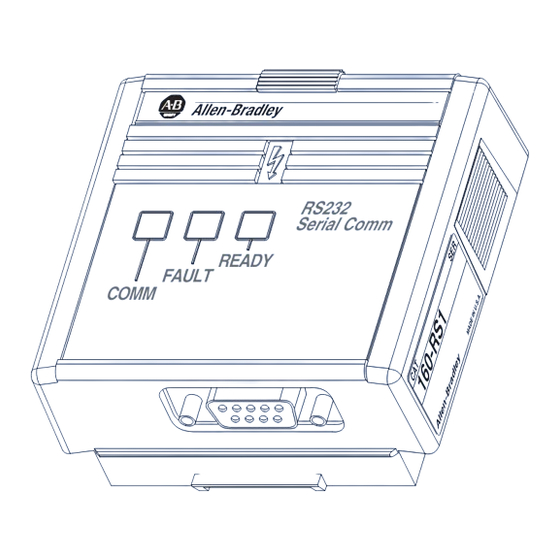
Chapter Product Overview This chapter contains the following information: • The physical layout of the module. • Location of configuration switches. • Overview and components. Module Description The RS1 Module is an optional interface device designed to provide a direct, digital link between RS-232 devices and the 160 Drive. The module connects to the drive through the expansion/keypad port on the front of the drive. -
Page 8: Configuration Dip Switches
1–2 Product Overview Configuration DIP Switches The Communication Module has one four position DIP switch for setting the baud rate, protocol and checksum type. DIP switches are located on the rear of the module (see below) and are only accessible when the module is removed from the 160 Drive. -
Page 9: Required Tools And Equipment
This chapter can help you start using the RS1 Communication Module. If you have installed or configured a network previously and are familiar with Allen-Bradley communication modules and drives, this information can help reduce the time of installation. If you are uncertain, use the full installation/configuration information... -
Page 10: Procedures
2–2 Quick Start for Experienced Users Procedures For Further Information Step Action Refer to . . . Review Attention statements in the Preface. Ensure that power has been removed to the 160 Drive. 160 Drive User Manual Verify that the 160 Drive is correctly installed and 160 Drive wired. -
Page 11: Emc Directive 89/336/Eec Compliance
Chapter Installation and Wiring This chapter contains information needed to: • Meet the requirements of the EMC and Low Voltage directives for CE compliance. • Remove a pre-installed Program Keypad Module or Ready/Fault Indicating Panel. • Configure and install the RS1 Module. •... -
Page 12: Module Configuration Switches
3–2 Installation and Wiring Module Configuration Switches The RS1 Module utilizes a four position DIP switch (see figure below) to configure the baud rate, protocol and checksum. These switches must be set to match the application settings. Refer to the paragraphs that follow for details. -
Page 13: Setting The Protocol - Sw3
Installation and Wiring 3–3 Setting the Protocol – SW3 As shown in the table below, SW3 sets the protocol being used (point- to-point or multi-drop). If EPROM Mode is active (SW1 & SW2 are On), the protocol will be read from P108 - [EPROM Protocol]. Important: If an “AIC+”... -
Page 14: Module Installation/Removal
3–4 Installation and Wiring Module Installation/Removal ATTENTION: The drive contains high voltage capacitors which take time to discharge after removal of mains supply. Before installing or removing a keypad/module, ensure iso- lation of mains supply from line inputs L1, L2, L3 (R, S, T). -
Page 15: Removing The Rs1 Module
Installation and Wiring 3–5 Figure 3.3 Communication Module Installation Latch must be in this position before installation. Once installed, push the latch down until it locks into place. Module should be flush with top surface of drive Removing the RS1 Module If you need to reconfigure the RS1 Module DIP switches, you must remove the module from the drive. -
Page 16: Wiring The Connector
3–6 Installation and Wiring Wiring the Connector The examples below can be used as a guide when wiring. Important: Keep communication wiring away from high noise sources such as motor cables. Figure 3.5 Wiring the RS1 Connector Pin 1 Pin 9 9 Pin, Female D-Shell Connector Personal Computer Serial Connections RS1 Module... - Page 17 Installation and Wiring 3–7 Figure 3.5 Wiring the RS1 Connector - continued SLC 500 Port 1 Serial Communications RS1 Module SLC RS-232 Port 9 Pin, Male , D-Shell Connector 9 Pin, Female , D-Shell Connector RS232 Serial Comm N.C. N.C. READY FAULT COMM...
-
Page 18: Connecting The Communication Cable To The Module
3–8 Installation and Wiring Connecting the Communication Follow these steps to connect your module. Cable to the Module 1. Verify that the cable/connector is correctly wired (See Figure 3.5). 2. Locate the D-shell connector at the base of the RS1 Module. 3. -
Page 19: Powering Up The Drive
Chapter Modes of Operation Chapter 4 contains the following information: • Powering up the drive with the RS1 Module installed. • The modes of operation and LED indications. Powering Up the Drive After you have installed the RS1 Module, apply power to the drive and to the connected device. -
Page 20: Power-Up Mode
4–2 Modes of Operation Modes of Operation The RS1 Module has three modes of operation. • Power-up mode • Run mode • Error mode Power-up Mode The following sequence of operation occurs: 1. During power-up, the READY LED illuminates. 2. The module reads and stores the DIP switch settings. If the power-up sequence is successful, the module enters the run mode and the COMM LED flashes green or turns solid green. -
Page 21: Supported Pccc Command List
Supported PCCC Command The RS1 Module communicates over RS-232 using the List Allen-Bradley DF1 protocol. The DF1 protocol uses PCCC (Programmable Controller Communication Commands) to determine the data format. PCCC describes the action of the message (set or get) and the location of the data involved. For further PCCC information, refer to DF1 Protocol and Command Set Reference Manual, publication 1770-6.5.16. - Page 22 5–2 RS1 Data Table Interface Table 5.B Data Table Format Parameter Number File Address Description None N10:0 Total number of drive & RS1 parameters (R/W - values only). Parameters 1-1xx N10:1 - N10:1xx Drive parameter value read or write. 160 drive parameters 1-99 and RS1 parameters 100-1xx.
- Page 23 RS1 Data Table Interface 5–3 Parameter Read Full Response Format Data Word Description Character Parameter Value or Status Word Descriptor Multiply Value Divide Value Base Value Offset Value Parameter Text Parameter Text Parameter Text Parameter Text Parameter Text Parameter Text Parameter Text Parameter Text File, Group, Element...
- Page 24 5–4 RS1 Data Table Interface 6. Reference Command (N41:1) Writing sends a speed reference to the 160 drive. This is a scaled speed reference from 0 to 32767, where 0 = 0 Hz and 32767 = P33 - [Maximum Frequency]. 7.
-
Page 25: Rs1 Parameters
Chapter Parameter Descriptions This chapter provides a listing and description of the RS1 Parameters. Important: Refer to your 160 User Manual for drive parameter descriptions. RS1 Parameters The RS1 Module contains a set of parameters that are used to define how the module will interact with the network. - Page 26 6–2 Parameter Descriptions Parameter Number Drive Min./Max. Access [Parameter Name] and Description Values Default (N10:, N30:) (N13:, N33:) Read/Write [EPROM BAUD] 1 to 4 9600 Baud The baud rate used when SW1 & SW2 are set to “On” (EPROM Mode). 1 = 1200 Baud 2 = 2400 Baud 3 = 4800 Baud...
- Page 27 Parameter Descriptions 6–3 Parameter Number Drive Min./Max. Access [Parameter Name] and Description Values Default (N10:, N30:) (N13:, N33:) Read [DIP Switches] 0 to 0xF 0000 Displays the current DIP switch settings. 0 to 15 Description Switch 9600 (Default) SW1, 2400 1200 EPROM Mode DF1 Point-to-Point (Default) SW3...
- Page 28 6–4 Parameter Descriptions End of Chapter 6...
-
Page 29: Required Items
Chapter Using the RS1 Module with DriveExplorer™ Software The purpose of this chapter is to provide an overview of the steps needed to use the Bulletin 9306 DriveExplorer software program with the RS1 Module and 160 Drive. DriveExplorer is a Windows® 95/ Windows NT®/Windows®... -
Page 30: Setting Baud Rates And Configuring The Communications Port
7–2 Using the RS1 Module with DriveExplorer™ Software Setting Baud Rates and 1. Before proceeding, the RS1 Module baud rate should be set as desired and the module installed as explained in Chapter 3. Configuring the Communications Port 2. The PC serial port must now be configured using DriveExplorer. A. -
Page 31: Uploading Editable Parameters
Using the RS1 Module with DriveExplorer™ Software 7–3 Uploading Editable Parameters It is possible to upload editable parameters and their values (in internal units) from the drive and store them in a file. There are three upload options: upload all parameters, upload selected parameters, and upload links. - Page 32 7–4 Using the RS1 Module with DriveExplorer™ Software End of Chapter 7...
-
Page 33: Required Tools
Programmable Controller This chapter provides an overview of the steps needed to use the RS1 Module with a MicroLogix 1000 (or other Allen-Bradley programmable controllers). The programmable controller can send control messages to the RS1 Module and receive status messages back. -
Page 34: Setting The Drive To Enable Network Control
8–2 Using the RS1 Module with a Programmable Controller Setting the Drive to Enable The 160 drive must be configured to accept logic and speed commands from the network. This can be done by configuring two of Network Control the 160 parameters: 1. -
Page 35: Program The Ladder
Using the RS1 Module with a Programmable Controller 8–3 Program the Ladder The example ladder program in Figure 8.2 demonstrates writing a Logic Command to the drive and reading the Logic Status from the drive. In the following example ladder program, B3:0/0 is set every 2 seconds. -
Page 36: Reading And Writing Parameters
8–4 Using the RS1 Module with a Programmable Controller Figure 8.2 Writing Logic Command and Reading Logic Status LAD 3 - DF 1 LOGIC --- Total Rungs in File = 5 This rung writes the Logic Command - Data in N7:8 is written to the Drive at N41:0 Enable for the Logic command Write B3:0... -
Page 37: Program The Ladder For Parameter Reads And Writes
Using the RS1 Module with a Programmable Controller 8–5 You can read or write RS1 Module parameters through location N10 or N13. For location N10, the RS1 parameters start at N10:101, thus accessing location N10:101 reads or writes RS1 parameter P1 - [Node Address]. - Page 38 8–6 Using the RS1 Module with a Programmable Controller Figure 8.4 Reading and Writing Drive Parameters LAD 5 - PARAMETER --- Total Rungs in File = 5 Parameter Write - when it's time to perform a parameter write B3:0.4 and B3:1.4 will be set. Data from N7:51 will written out Channel 0 to the 160 - RS1 module at location N10:30 (parameter 30).
-
Page 39: Led Indicators And Troubleshooting
Chapter Troubleshooting The purpose of this chapter is to help you troubleshoot your RS1 Module. ATTENTION: Servicing energized industrial control equipment can be hazardous. Electrical shock, burns, or un- intentional actuation of controlled industrial equipment may cause death or serious injury. Follow the safety-related practices of NPFA 70E, Electrical Safety for Employee Workplaces, when working on or near energized equipment. -
Page 40: Ready Led
9–2 Troubleshooting READY LED The green READY LED will illuminate whenever the RS1 Module is connected to the drive and power is applied. COMM LED The COMM LED provides status information on module operations. Table 9.A shows how to use the LED to detect and correct common operating problems. -
Page 41: Rs1/Df1 Error Codes
Troubleshooting 9–3 Table 9.B (continued) 160 Drive1 Fault Codes Fault Code Fault Indication Description Corrective Action Phase W Fault Phase to ground fault detected between drive Check wiring between drive and motor. Check motor and motor phase W. for grounded phase. UV Short Fault Excessive current has been detected between Check the motor and external wiring to the drive... - Page 42 9–4 Troubleshooting End of Chapter 9...
-
Page 43: Electrical
Appendix Specifications Electrical Supply Voltage Supplied by Drive Power Consumption 1.25 Watts maximum Environmental Ambient Temperature Operating 0 to 50° C (32 to 122° F) Storage –40 to 85° C (–40 to 185° F) Relative Humidity 0 to 95% non-condensing Vibration 1.0 G Operational 2.5 G Non-operational... - Page 44 A–2 Specifications End of Appendix A...
- Page 45 Appendix RS1 Module Compatibility The 160-RS1 Module has been tested and found to be compatible with the following Allen-Bradley products: • MicroLogix 1000 Protocol Point-to-Point PCCC Command 0xA1 Protected Type Logical Read with 2 Address Fields 0xA9 Protected Type Logical Write with 2 Address Fields...
- Page 46 B–2 RS1 Module Compatibility End of Appendix B...
- Page 47 Index Logic Command/Status, 5–3 Baud Rate, Setting, 3–2 BCC Checksum, 3–3 Modes of Operation Error Mode, 4–2 Power-up Reset, 4–2 Cabling, 3–6 Run Mode, 4–2 CE Compliance, 3–1 Module Installation, 3–4 Checksum Mode Setting, 3–3 CRC Checksum, 3–3 Parameter Descriptions, 6–1 Parameters Downloading, 7–3 Data Table Interface, 5–1...
- Page 48 I–2 Index Notes...
- Page 50 Publication 0160-5.14 – March, 1999 P/N 189177 (02) Supersedes October, 1998 Copyright 1999 Rockwell International Corporation. All rights reserved. Printed in USA...
Need help?
Do you have a question about the 160-RS1 and is the answer not in the manual?
Questions and answers