
Subscribe to Our Youtube Channel
Related Manuals for Allen-Bradley 1606-XLS960BUFFER


Summary of Contents for Allen-Bradley 1606-XLS960BUFFER
- Page 1 Buffer Module - 24V, 40 A, 160 ms Catalog Number 1606-XLS960BUFFER Reference Manual Original Instructions...
- Page 2 Buffer Module - 24V, 40 A, 160 ms Reference Manual Important User Information Read this document and the documents listed in the additional resources section about installation, configuration, and operation of this equipment before you install, configure, operate, or maintain this product. Users are required to familiarize themselves with installation and wiring instructions in addition to requirements of all applicable codes, laws, and standards.
-
Page 3: Table Of Contents
Table of Contents Terminology and Abbreviations ........5 Product Overview . - Page 4 Table of Contents Notes: Rockwell Automation Publication 1606-RM105A-EN-P - July 2020...
-
Page 5: Terminology And Abbreviations
Terminology and Terminology Descriptions Abbreviations Describes a condition where the supply voltage is in the rated supply voltage range and the Power supply mode supplying power supply can deliver enough current for the buffer module and the load. This mode can also be called “Normal mode”. Describes a condition where the input voltage is below the transfer threshold level, the unit Buffer mode is running on capacitors (buffering), and the output is loaded within the allowed limits. -
Page 6: Specifications
64 x 124 x 142 mm Dimensions W x H x D (2.52 x 4.88 x 5.59 in.) Weight 1040 g (2.3 lb) — Catalog Numbers Catalog Numbers Descriptions 1606-XLS960BUFFER Buffer module 1606-XLC Panel/wall-mount bracket 1606-XLA-S76 Side-mount bracket Rockwell Automation Publication 1606-RM105A-EN-P - July 2020... -
Page 7: Functional Description
Functional Description This section describes how the buffer module works in general and some specific uses. Figure 1 - Typical Wiring Diagram Figure 2 - Transfer Behavior Power Transfer Threshold Supply Output Power Buffer Load Supply Module Supply Voltage optional Power Power Buffer... -
Page 8: Electrical Ratings
Electrical Ratings Attributes Values Notes -20%/+25% Supply voltage — DC 24V 19.2…30V DC — Supply voltage range 23…30V DC — Normal operating voltage range 22.5V DC Back-up threshold jumper set to “22.5V fixed” Transfer voltage for switching into – 1V Back-up threshold jumper set to “V –... -
Page 9: Select The Backup Threshold Voltage
Select the Backup The functionality of the buffer is determined by what mode the buffer is in, either Fixed mode or Variable mode. You can set the mode using the backup Threshold Voltage jumper selector. The factory default setting is Fixed mode. If the buffer has no jumper, it is also in Fixed mode. -
Page 10: Buffer Time
Buffer Time The buffer time (sometimes also called autonomy time) is the maximum period for which the capacitor can maintain the required output current. The buffer time mainly depends on the output current in buffer mode. To increase the buffer time, any given number of buffer modules can be connected in parallel. -
Page 11: Operating Diagrams
Operating Diagrams Figure 8 - Operating Diagram Figure 9 - Signal Schematic Hold-up Time Power Supply Mains Buffer Capacitor 7 Active Optocoupler high ohmic Ready Optocoupler 8 Ready low ohmic 5,1V Optocoupler high ohmic Active Optocoupler low ohmic 3 mA 1.25 Hz 10 Hz 9 Inhibit... -
Page 12: Inhibit Input
Inhibit Input Buffering can be disabled or interrupted with the Inhibit input (pin 9). To use the Inhibit input, connect pin 6 to either the positive pole of the terminal voltage or to the external control voltage, and connect pin 9 to the corresponding negative pole. -
Page 13: Functional Diagram
Functional Diagram Figure 10 - Functional Diagram Status Buffer Capacitor Charger & Inrush Limiter Buffer Safety and Reverse- Capacitor Over- Polarity Shut-Down Buffer Capacitor Supply Voltage Protection Voltage Discharger Protection Buffer Capacitor 6 (+) 9 Inhibit Chassis Opto-coupler Ground Input / Output Voltage Monitor 8 Ready Back-up... -
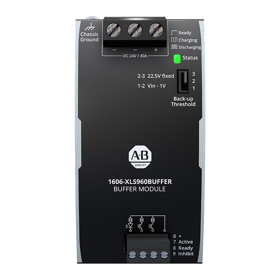
Page 14: Front Side And User Elements
Front Side and User Elements Figure 11 - Front Side of Buffer Module User Elements Chassis Ground Terminal To be connected on the top side of the housing with a ring-type terminal (ring cable lug) which is suitable for an M4 screw. -
Page 15: Electromagnetic Compatibility
Electromagnetic The buffer module is suitable for applications in industrial, residential, commercial, and light industry environments. Compatibility The following table shows the EMC immunity for all operating modes according to generic standards EN 61000-6-1 and EN 61000-6-2. Attributes Standards Values Criteria 8 kV Contact discharge... -
Page 16: Environment
Environment Attributes Values Notes -25…+70 °C (-13…158 °F) — Operational temperature Storage temperature -40…+70 °C (-40…158 °F) For storage and transportation 5...95% r.H. IEC 60068-2-30 Humidity 2…12.5 Hz: ±1.6 mm (0.06 in.); Vibration sinusoidal 12.5…500 Hz: 1 g IEC 60068-2-6 2 hours / axis 0.5 m²(s³) Vibration random... -
Page 17: Dielectric Strength
Dielectric Strength The signal port (active and ready signal and inhibit input) is floating and separated from the supply voltage. The manufacturer conducts type and factory tests. Field tests can be conducted in the field using the appropriate test equipment, which applies the voltage with a slow ramp (2 seconds up and 2 seconds down). -
Page 18: Physical Dimensions And Weight
Physical Dimensions and Attributes Values and Notes Weight Width 64 mm (2.13 in.) Height 124 mm (4.88 in.) 142 mm (5.59 in.) Depth The DIN rail height must be added to the unit depth to calculate the total required installation depth. Weight 1040 g (2.3 lb) Use 35 mm (1.38 in.) DIN rails according to EN 60715 or EN... -
Page 19: Mounting Brackets
Mounting Brackets This section describes the brackets that can be used to mount the buffer module. Wall Mounting Bracket 1606-XLC This bracket is used to mount the buffer module on a wall without using a DIN rail. To mount a unit on a wall or a panel, the two Zinc-plated steel brackets have to be installed on the side of the unit. -
Page 20: Side Mounting Bracket 1606-Xla-S76
Side Mounting Bracket 1606-XLA-S76 This bracket is used to mount the buffer module sideways with or without using a DIN rail. The two aluminum brackets and the black plastic slider of the unit have to be detached, so that the steel brackets can be mounted. For sideway DIN rail mounting, the removed aluminum brackets and the black plastic slider must be mounted on the steel bracket. -
Page 21: Wiring Diagram
Wiring Diagram In all figures in this section, the buffer module is the 1606-XLS960BUFFER. Where a redundancy module is shown, it is the 1606-XLSRED40. Figure 20 - General Wiring Diagram Figure 21 - Signals Supplied from an External Voltage Source... - Page 22 Notes: Rockwell Automation Publication 1606-RM105A-EN-P - July 2020...
-
Page 23: Additional Resources
Automation products in a secure system, harden the control system, manage user access, and dispose of equipment. Industrial Components Preventive Maintenance, Enclosures, and Contact Provides a quick reference tool for Allen-Bradley industrial automation controls and Ratings Specifications, publication IC-TD002 assemblies. - Page 24 At the end of life, this equipment should be collected separately from any unsorted municipal waste. Rockwell Automation maintains current product environmental information on its website at rok.auto/pec. Allen-Bradley, expanding human possibility, and Rockwell Automation are trademarks of Rockwell Automation, Inc. Trademarks not belonging to Rockwell Automation are property of their respective companies.
Need help?
Do you have a question about the 1606-XLS960BUFFER and is the answer not in the manual?
Questions and answers