Allen-Bradley ControlLogix DeviceNet 1756-DNB Installation Instructions Manual
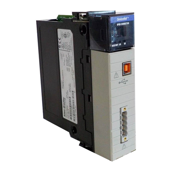
Scanner module
Hide thumbs
Also See for ControlLogix DeviceNet 1756-DNB:
- Configuration manual (68 pages) ,
- Installation instructions manual (68 pages) ,
- Installation instructions manual (29 pages)
Table of Contents
Advertisement
Quick Links
ControlLogix DeviceNet
Scanner Module
Catalog Number 1756-DNB
Use this manual as a guide to install the ControlLogix™ DeviceNet™
Scanner Module. The following table identifies what this manual
contains and where to find specific information.
Topic
Installation Instructions
See Page
3
4
5
6
7
8
9
10
11
12
13
13
14
16
19
21
25
27
Advertisement
Table of Contents

Subscribe to Our Youtube Channel
Related Manuals for Allen-Bradley ControlLogix DeviceNet 1756-DNB


Summary of Contents for Allen-Bradley ControlLogix DeviceNet 1756-DNB
-
Page 1: Table Of Contents
Installation Instructions ControlLogix DeviceNet Scanner Module Catalog Number 1756-DNB Use this manual as a guide to install the ControlLogix™ DeviceNet™ Scanner Module. The following table identifies what this manual contains and where to find specific information. Topic See Page European Communities (EC) Directive Compliance Preventing Electrostatic Discharge Understand the Module’s Software Features Identify Module Components... - Page 2 2 ControlLogix DeviceNet Scanner Module Throughout this manual we use the following notes to make you aware of safety considerations: Identifies information about practices or WARNING circumstances that have the potential to create an explosion hazard. Identifies information about other practices or ATTENTION circumstances that can lead to personal injury or death, property damage or economic loss.
-
Page 3: European Communities (Ec) Directive Compliance
Voltage, by applying the safety requirements of EN 61131-2 Programmable Controllers, Part 2 - Equipment Requirements and Tests. For specific information required by EN 61131-2, see the appropriate sections in this publication, as well as the following Allen-Bradley publications: • Industrial Automation Wiring and Grounding Guidelines, publication 1770-4.1 •... -
Page 4: Preventing Electrostatic Discharge
4 ControlLogix DeviceNet Scanner Module Enclosure and Environmental Requirements Specific To This Product This product must be mounted within a suitable system enclosure to prevent personal injury resulting from accessibility to live parts. The interior of this enclosure must be accessible only by the use of a tool. This industrial control equipment is intended to operate in a Pollution Degree 2 environment, in overvoltage category II applications, (as defined in IEC publication 664A) at altitudes up to 2000 meters... -
Page 5: Understand The Module's Software Features
ControlLogix DeviceNet Scanner Module 5 Understand the Module’s Software Features The 1756-DNB module has the software features described in the following sections. You activate these features by using RSNetWorx for DeviceNet™ software (catalog no. 9357-DNETL3). For more information, refer to the appropriate RSNetWorx for DeviceNet documentation, and to the 1756-DNB Scanner User Manual, publication 1756-UM515C-EN-P. -
Page 6: Identify Module Components
6 ControlLogix DeviceNet Scanner Module Change of state increases system performance by reducing network traffic, since data is only sent on an as-needed basis. Use RSNetWorx for DeviceNet software to activate this feature. Cyclic I/O The scanner module can send and receive data on a cyclic basis with slave devices that also have this feature. -
Page 7: Prepare To Install The Module
ControlLogix DeviceNet Scanner Module 7 Prepare to Install the Module Before you install the module, make sure that you have these components. 1756-DNB module 1756-A4, 1756-A7, or 1756-A10 chassis 1756-PA72/75 or 1756-PB72/75 power supply DeviceNet open-style or small screwdriver 10-position connector DeviceNet truck or drop cable Publication 1756-IN566B-EN-P - April 2001... -
Page 8: Installing Or Removing The Module Under Power
8 ControlLogix DeviceNet Scanner Module Installing or Removing the Module Under Power This module is designed to be installed or removed while chassis power is applied. When you insert or remove a module while WARNING backplane power is on, an electrical arc may occur. -
Page 9: Determine Module Slot Location
ControlLogix DeviceNet Scanner Module 9 For information on installing these products, refer to the publications listed in the following table. Chassis Chassis Power Power Supply Type Installation Supply Installation Series B: 1756-A4, -A7, -A10, -A13 Pub. No. 1756-PA72/B Pub. No. 1756-IN080 1756-5.67 1756-PB72/B... -
Page 10: Install The Module
10 ControlLogix DeviceNet Scanner Module Install the Module Align the circuit board with top and bottom guides in the chassis. POWER Circuit board Slide the module into the chassis. Make sure the module properly connects to the chassis backplane. The module is fully installed when it is flush with the power supply or other installed modules. -
Page 11: Remove Or Replace The Module
ControlLogix DeviceNet Scanner Module 11 Remove or Replace the Module If you are replacing an existing 1756-DNB module IMPORTANT with another 1756-DNB module and you want to resume identical system operation, you must install the new module in the same slot. Push on upper and lower module tabs to disengage them. -
Page 12: Wire The Devicenet Connector
12 ControlLogix DeviceNet Scanner Module Wire the DeviceNet Connector Use an open-style 5- or 10-position linear plug to connect to the DeviceNet network. An open-style 10-position linear plug is provided with your module. For detailed DeviceNet connection information, IMPORTANT see the DeviceNet Cable System Planning and Installation Manual, publication DN-6.7.2. -
Page 13: Connect The Module To The Devicenet Network
ControlLogix DeviceNet Scanner Module 13 Connect the Module to the DeviceNet Network Attach the connector to the module’s DeviceNet port as shown below. Tighten the screws on the connector as needed. 10-position DeviceNet Port Connector linear plug DeviceNet Drop Line or Trunk Connector Apply Chassis Power Power supply indicator is green when power supply is working correctly. -
Page 14: Using The Manual Configuration Pushbutton
14 ControlLogix DeviceNet Scanner Module 1. Firmware major revision (01 through 128) DeviceNet 2. Firmware minor revision (01 through 255) 3. Optional Firmware Build Number 4. Baud rate (125, 250, or 500) 5. MAC ID (00 to 63) Alphanumeric Display MOD/NET I/O Manual Configuration... - Page 15 ControlLogix DeviceNet Scanner Module 15 The module’s alphanumeric display cycles through the allowable baud rates (125k 250k, 500k). 2. Release the button when the baud rate you want to select is shown on the display. If your module is connected to the network: 1.
-
Page 16: Interpreting The Alphanumeric Display
16 ControlLogix DeviceNet Scanner Module Interpreting the Alphanumeric Display Your 1756-DNB scanner module displays alphanumeric codes that provide diagnostic information about your module. The alphanumeric display flashes the codes at approximately 1 second intervals. What is Displayed? As an example, the display for RUN toggles between the network address and the mode: A#01 If there is a problem, the display shows the network address,... - Page 17 ControlLogix DeviceNet Scanner Module 17 Alphanumeric Status Codes Code Description Recommended Action Data overrun on port detected. Modify your configuration and check for invalid data. Check network communication traffic. No traffic detected on the network. Check the network configuration. No direct network traffic for scanner None.
- Page 18 18 ControlLogix DeviceNet Scanner Module Alphanumeric Status Codes Code Description Recommended Action Bus-off condition detected on comm Check DeviceNet connections and port. Scanner is detecting physical media integrity. Check system communication errors. for failed slave devices or other possible sources of network interference.
-
Page 19: Interpreting The Led Status Indicators
ControlLogix DeviceNet Scanner Module 19 Interpreting the LED Status Indicators The three LED status indicators on the module provide information about your network and its connections. The following tables outline the indicator condition and the corresponding status, and explain what each condition means. Module/Network (MOD/NET) Status Indicator This bi-color (green/red) LED provides device and communication status as follows:... - Page 20 20 ControlLogix DeviceNet Scanner Module I/O Status Indicator This bi-color (green/red) LED indicates the status of the 1756-DNB’s I/O scanning state. The I/O Status LED informs you whether this device has outputs under control and whether any outputs or inputs are active (outputs active, inputs producing, etc.) or faulted.
-
Page 21: Controllogix Controller Interface
ControlLogix DeviceNet Scanner Module 21 ControlLogix Controller Interface The 1756-DNB module supports several different size input, output, and status structures over the ControlLogix backplane. These I/O structures were created to reduce the complexity of connecting DeviceNet I/O and status data with ladder programs. The module creates all 3 structures whether or not DeviceNet nodes are configured or online. - Page 22 22 ControlLogix DeviceNet Scanner Module Module Command Register Bit Definitions The bits of the Module Command Register are defined as follows: Name Description 1 = run mode 0 = idle mode Fault 1 = fault network DisableNetwork 1 = disable network HaltScanner 1 = halt module (the DNB module ceases all operation.)
- Page 23 ControlLogix DeviceNet Scanner Module 23 Module Status Register Bit Definitions The bits of the Module Status Register are defined as follows: Name Description 1 = in run mode. 0 = in idle mode. Fault 1 = network is faulted. DisableNetwork 1 = network is disabled.
- Page 24 24 ControlLogix DeviceNet Scanner Module The status structure consists of these data elements: Status Structure Description Data Type DINTS Element ScanCounter counter incremented each I/O scan 32-bit DeviceFailureRegister device failed bit table; 1 = failed 64-bit AutoverifyFailureRegister device I/O size does not match 64-bit scanner’s internal table;...
-
Page 25: Hazardous Location Information
ControlLogix DeviceNet Scanner Module 25 Hazardous Location Information The following information applies when operating this equipment in hazardous locations: Products marked “CL I, DIV 2, GP A, B, C, D” are suitable for use in Class I Division 2 Groups A, B, C, D, Hazardous Locations and nonhazardous locations only. - Page 26 26 ControlLogix DeviceNet Scanner Module Informations sur l’utilisation de cet équipement en environnements dangereux: Les produits marqués “CL I, DIV 2, GP A, B, C, D” ne conviennent qu’à une utilisation en environnements de Classe I Division 2 Groupes A, B, C, D dangereux et non dangereux. Chaque produit est livré...
-
Page 27: Specifications
ControlLogix DeviceNet Scanner Module 27 Specifications Parameter Specification Module Location any slot in the ControlLogix chassis Maximum Backplane Current Load 600mA @ 5.0V dc and 3mA @ 24V dc from ControlLogix chassis backplane Maximum DeviceNet Current Load 90mA maximum @11-25V dc 30mA typical @ 11-25V dc Power Dissipation 5.3W maximum... -
Page 28: Publication 1756-In566B-En-P - April
ControlLogix is a trademark of Rockwell Automation. DeviceNet is a trademark of Open DeviceNet Vendors Association (ODVA). RSLogix 5000 and RSNetWorx for DeviceNet are trademarks of Rockwell Software Inc. Publication 1756-IN566B-EN-P - April 2001 PN 957536-69 Supersedes Publication 1756-5.66 - May 1998 ©...
Need help?
Do you have a question about the ControlLogix DeviceNet 1756-DNB and is the answer not in the manual?
Questions and answers