Table of Contents
Advertisement
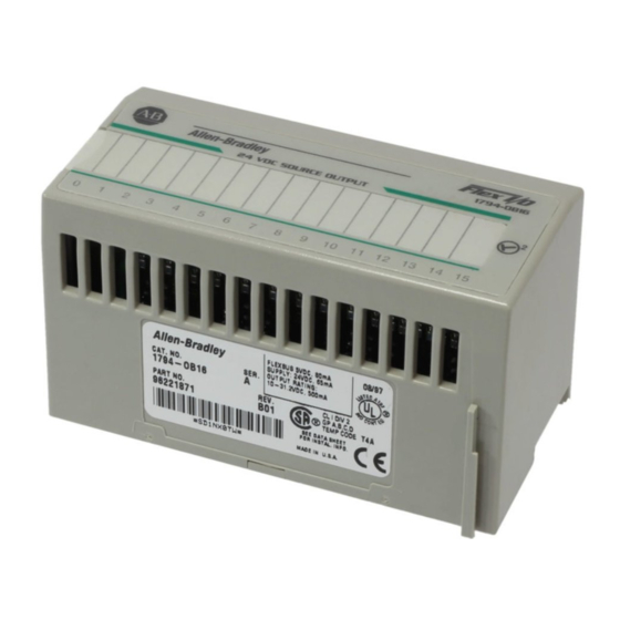
24V dc FLEX I/O
16 Source Output Module
(Cat. No. 1794-OB16)
4
Module Installation
This module mounts on a 1794 terminal base unit.
1. Rotate keyswitch (1) on terminal base unit (2) clockwise to position 2
as required for this type of module.
2. Make certain the flexbus connector (3) is pushed all the way to the left
to connect with the neighboring terminal base/adapter. You cannot
install the module unless the connector is fully extended.
3. Make sure that the pins on the bottom of the module are straight so
they will align properly with the connector in the terminal base unit.
4. Position the module (4) with its alignment bar (5) aligned with the
groove (6) on the terminal base.
5. Press firmly and evenly to seat the module in the terminal base unit.
The module is seated when the latching mechanism (7) is locked into
the module.
ATTENTION: To use this module in a complementary
!
I/O system, refer to your Remote I/O Adapter module
documentation.
FLEX I/O is a trademark of Rockwell Automation
Installation Instructions
3
7
1
2
6
5
Publication 1794-5.3 – July 1999
Advertisement
Table of Contents

Related Manuals for Allen-Bradley 1794-OB16


Summary of Contents for Allen-Bradley 1794-OB16
- Page 1 Installation Instructions 24V dc FLEX I/O 16 Source Output Module (Cat. No. 1794-OB16) Module Installation This module mounts on a 1794 terminal base unit. 1. Rotate keyswitch (1) on terminal base unit (2) clockwise to position 2 as required for this type of module.
- Page 2 24V dc FLEX I/O 16 Source Output Module ATTENTION: Remove field-side power before removing or inserting this module. This module is designed so you can remove and insert it under backplane power. When you remove or insert a module with field-side power applied, an electrical arc may occur.
- Page 3 24V dc FLEX I/O 16 Source Output Module 3 Wiring to a 1794-TB2, -TB3 or -TB3S Terminal Base Unit 1. Connect individual outputwiring to numbered terminals on the 0–15 row (A) as indicated in the table below. 1. Connect the associated output common to the corresponding terminal on the 16–33 row (B) for each output as indicated in the table below.
- Page 4 24V dc FLEX I/O 16 Source Output Module Output Common Output Common Output Output Terminal Terminal Terminal Terminal Output 0 A–0 B–17 Output 8 A–8 B–25 Output 1 A–1 B–18 Output 9 A–9 B–26 Output 2 A–2 B–19 Output 10 A–10 B–27 Output 3...
- Page 5 24V dc FLEX I/O 16 Source Output Module 5 Specifications – 24V dc Output Module Cat. No. 1794-OB16 Number of Outputs 16 (1 group of 16), non-isolated, sourcing Module Location Cat. No. 1794-TB3, -TB3S Terminal Base Unit ON-state Voltage Range 10V dc minimum 24V dc nominal;...
- Page 6 24V dc FLEX I/O 16 Source Output Module Specifications – 24V dc Output Module Cat. No. 1794-OB16 General Specifications External dc Power Supply Voltage 24V dc nominal Voltage Range 19.2 to 31.2V dc (includes 5% ac ripple) Supply Current 49mA @ 24V dc (38 to 65mA)
- Page 7 24V dc FLEX I/O 16 Source Output Module 7 CSA Hazardous Location Approval Approbation d’utilisation dans des emplacements dangereux par la CSA CSA certifies products for general use as well as La CSA certifie les produits d’utilisation générale for use in hazardous locations. Actual CSA aussi bien que ceux qui s’utilisent dans des certification is indicated by the product label emplacements dangereux.
- Page 8 24V dc FLEX I/O 16 Source Output Module CSA Hazardous Location Approval Approbation d’utilisation dans des emplacements dangereux par la CSA ATTENTION: Explosion hazard — AVERTISSEMENT: Risque d’explosion — Substitution of components may La substitution de composants peut impair suitability for Class I, rendre ce matériel inacceptable pour Division 2.
Need help?
Do you have a question about the 1794-OB16 and is the answer not in the manual?
Questions and answers