Allen-Bradley B series User Manual
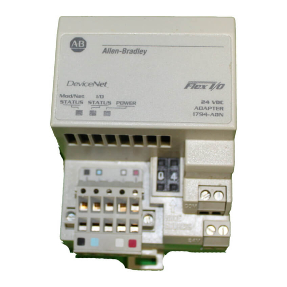
Communications adapter module, 24vdc, devicenet to flex i/o
Hide thumbs
Also See for B series:
- Service manual (148 pages) ,
- User manual (132 pages) ,
- Installation instructions manual (24 pages)
Table of Contents
Advertisement
Advertisement
Table of Contents

Related Manuals for Allen-Bradley B series


Summary of Contents for Allen-Bradley B series
- Page 1 Allen Bradley User DeviceNet Adapter Module Manual (Cat. No. 1794 ADN Series B)
- Page 2 DeviceNet, DeviceNetManager, and RediSTATION are trademarks of Allen-Bradley Company, Inc. PLC, PLC–2, PLC–3, and PLC–5 are registered trademarks of Allen-Bradley Company, Inc. Windows is a trademark of Microsoft. Microsoft is a registered trademark of Microsoft IBM is a registered trademark of International Business Machines, Incorporated.
-
Page 3: New Information
Summary of Changes This publication contains new and revised information not included in the last release. New Information Additional Flex I/O Modules The following modules have been added to this publication: 8 Electronically Fused Output Module, cat. no. 1794-OB8EP 10 Input/6 Output Module, cat. no. 1794-IB10XOB6 SCANport Module, cat. -
Page 4: Table Of Contents
Table of Contents Summary of Changes ......New Information ........Additional Flex I/O Modules . - Page 5 Table of Contents Mapping Data into the Image Table ..... . . 16 point Discrete Input Module (1794 IB16) Image Table Mapping Memory Map of 16 Point Discrete Input Module Image Table - 1794 IB16 .
- Page 6 Table of Contents Range Selection Bits for the 1794 IE4XOE2 Analog Combo Module ....... 2-17 Word/Bit Descriptions for the 1794 IE4XOE2 Analog Combo Module...
- Page 7 Table of Contents Configuring Your DeviceNet Adapter Online ... Chapter Objectives ........About DeviceNet Manager .
-
Page 8: About This Manual
Use this manual to install and configure your Flex I/O DeviceNet Adapter, cat. no. 1794-ADN Series B. Audience We assume that you have previously used an Allen-Bradley programmable controller, that you are familiar with its features, and that you are familiar with the terminology we use. If not, read the user manual for your processor before reading this manual. -
Page 9: Conventions
SP–2 About This Manual Conventions We use these conventions in this manual: In this manual, we show: Like this: that there is more information about a topic in another chapter in this manual that there is more information about the topic in another manual More Related Publications... -
Page 10: Installing Your Devicenet Adapter Module
Programmable Controllers, Part 2 – Equipment Requirements and Tests. For specific information required by EN 61131-2, see the appropriate sections in this publication, as well as the following Allen-Bradley publications: Industrial Automation Wiring and Grounding Guidelines For Noise Immunity, publication 1770-4.1 Guidelines for Handling Lithium Batteries, publication AG-5.4... -
Page 11: The Flex I/O System
1–2 Installing Your DeviceNet Adapter Module The FLEX I/O System FLEX I/O is a small, modular I/O system for distributed applications that performs all of the functions of rack-based I/O. The FLEX I/O system contains the following components as shown below: Adapter/Power Supply Terminal Base... -
Page 12: Diagnostic Indicators
Installing Your DeviceNet Adapter Module 1–3 Diagnostic Indicators Diagnostic indicators are located on the front panel of the adapter module. They show both normal operation and error conditions in your remote I/O system. The indicators are: Mod/Net status I/O status A complete description of the diagnostic indicators and how to use them for troubleshooting is explained in Chapter 5. -
Page 13: Mounting On A Wall Or Panel
1–4 Installing Your DeviceNet Adapter Module 3. Press the adapter module down onto the DIN rail until flush. Locking tab (C) will snap into position and lock the adapter module to the DIN rail. 4. If the adapter module does not lock in place, use a screwdriver or similar device to move the locking tab down while pressing the adapter module flush onto the DIN rail and release the locking tab to lock the adapter module in place. - Page 14 Installing Your DeviceNet Adapter Module 1–5 2. Drill the necessary holes for #6 self-tapping mounting screws. 3. Mount the mounting plate (1) for the adapter module using two #6 self-tapping screws (18 included). Important: Make certain that the mounting plate is properly More grounded to the panel.
-
Page 15: Setting The Network Address Switch
1–6 Installing Your DeviceNet Adapter Module Setting the Network Set the network address using the 2-position thumbwheel switch. Address Switch Valid settings range from 00 to 63. Press either the + or – buttons to change the number. Network Address Switches Note: The baud rate for the adapter is set by way of “baud detection”... -
Page 16: Wiring
Installing Your DeviceNet Adapter Module 1–7 Wiring Connect external wiring to the DeviceNet adapter as shown below. DeviceNet Connector 20131 1. Connect the DeviceNet cable to the removable connector as shown. Connect BLK Wire BLU Wire CAN* Low Bare Wire Drain WHT Wire CAN High... -
Page 17: Chapter Summary
1–8 Installing Your DeviceNet Adapter Module Chapter Summary In this chapter you learned about the FLEX I/O system, how to install your DeviceNet adapter module and set your switches. Chapter 2 tells you how to communicate with your system. Publication 1794 6.5.5 - October 1996... -
Page 18: How Communication Takes Place And I/O Image Table Mapping
Chapter How Communication Takes Place and I/O Image Table Mapping Chapter Objectives In this chapter, you will learn about: communication over the Flex I/O backplane (between the DeviceNet adapter and the I/O modules) how data is mapped into the I/O image table Communication Over the One 1794-ADN DeviceNet adapter can interface with up to eight Flex I/O Backplane... -
Page 19: I/O Structure
2–2 How Communication Takes Place and I/O Image Table Mapping For example, a 16 point discrete input module will have up to 2 read words and 1 write word. Module Image I/O Image Input Size Inputs Not used Output Size Delay Delay Not used... -
Page 20: Adapter Input Status Word
How Communication Takes Place and I/O Image Table Mapping 2–3 Adapter Input Status Word The input status word consists of: I/O module fault bits – 1 status bit for each slot node address changed – 1 bit I/O status – 1 bit The adapter input status word bit descriptions are shown in the following table. -
Page 21: Communication Choices
2–4 How Communication Takes Place and I/O Image Table Mapping Communication Choices The FLEX I/O DeviceNet adapter module supports multiple communication choices. These choices all use the default I/O structure previously described. The adapter master makes the actual communication choice. The choices are: Polled –... -
Page 22: 16 Point Discrete Input Module (1794 Ib16) Image Table Mapping
How Communication Takes Place and I/O Image Table Mapping 2–5 16 point Discrete Input Module (1794 IB16) Image Table Mapping I/O Image Module Image Input Size Inputs Read Not used Output Size Delay Delay Not used Write Time Time Memory Map of 16-Point Discrete Input Module Image Table – 1794-IB16 Decimal Bit Size... -
Page 23: Point Discrete Output Module (1794 Ob16) Image Table Mapping
2–6 How Communication Takes Place and I/O Image Table Mapping 16 point Discrete Output Module (1794 OB16) Image Table Mapping I/O Image Module Image Input Size Read Not used Output Size Outputs Write Not used Memory Map of 16-Point Discrete Output Module Image Table – 1794-OB16 Dec. -
Page 24: Point Discrete Electronically Fused Output Module (1794 Ob8Ep) Image Table Mapping
How Communication Takes Place and I/O Image Table Mapping 2–7 8 point Discrete Electronically Fused Output Module (1794 OB8EP) Image Table Mapping I/O Image Module Image Input Size Read Fault Bits Reserved Output Size Not used Outputs Write Reserved Memory Map of 8-Point Discrete Electronically Fused Output Module Image Table –... -
Page 25: Point Discrete Sensor Input Module (1794 Ib8S) Image Table Mapping
2–8 How Communication Takes Place and I/O Image Table Mapping 8 point Discrete Sensor Input Module (1794 IB8S) Image Table Mapping I/O Image Module Image Input Size Status Inputs Read Not used Output Size Delay Delay Not used Write Time Time Memory Map of 8-Point Discrete Sensor Input Module Image Table –... -
Page 26: Point Discrete Input Module (1794 Ia8) Image Table Mapping
How Communication Takes Place and I/O Image Table Mapping 2–9 8 point Discrete Input Module (1794 IA8) Image Table Mapping Module Image I/O Image Input Size Not used Inputs Read Not used Output Size Delay Not used Write Time Memory Map of 8-point Discrete Input Module Image Table – 1794-IA8 Dec. -
Page 27: Point Discrete Output Module (1794 Oa8) Image Table Mapping
2–10 How Communication Takes Place and I/O Image Table Mapping 8 point Discrete Output Module (1794 OA8) Image Table Mapping I/O Image Module Image Input Size Read Not used Output Size Not used Outputs Write Not used Memory Map of 8-point Discrete Output Module Image Table – 1794-OA8 Dec. -
Page 28: Input Analog Module (Cat. No. 1794 Ie8) Image Table Mapping
How Communication Takes Place and I/O Image Table Mapping 2–11 8 Input Analog Module (Cat. No. 1794 IE8) Image Table Mapping Module Image Input Data Channel 0 Input Data Channel 1 I/O Image Input Data Channel 2 Input Size Input Data Channel 3 Input Data Channel 4 Input Data Channel 5 Input Data Channel 6... -
Page 29: Range Selection Bits For The 1794 Ie8 Analog Input Module
2–12 How Communication Takes Place and I/O Image Table Mapping Range Selection Bits for the 1794-IE8 Analog Input Module Channel No. Channel 0 Channel 1 Channel 2 Channel 3 Channel 4 Channel 5 Channel 6 Channel 7 Decimal Bit Word/Bit Descriptions for the 1794-IE8 Analog Input Module Write Word Decimal Bit... -
Page 30: Output Analog Module (1794 Oe4) Image Table Mapping
How Communication Takes Place and I/O Image Table Mapping 2–13 Word Decimal Bit Definition Underrange bits (U) (4 20mA current input only) Power Up bit - included in series B modules only. This bit is 0 in series A modules. This bit is set to 1 when all bits in the configuration register are 0 (unconfigured state). -
Page 31: Memory Map Of Analog Output Module Image Table - 1794 Oe4
2–14 How Communication Takes Place and I/O Image Table Mapping Memory Map of Analog Output Module Image Table – 1794-OE4 Dec. Bit Size Size Oct. Bit ATTENTION: These bits must be set to 1. Range Selection Bits for the 1794-OE4 Analog Output Module (Write Word 6) Channel No. - Page 32 How Communication Takes Place and I/O Image Table Mapping 2–15 Word Decimal Bit Definition Channel 0 analog data Channel 0 analog data sign bit. Channel 1 analog data Channel 1 analog data sign bit. Channel 2 analog data Channel 2 analog data sign bit. Channel 3 analog data Channel 3 analog data sign bit.
-
Page 33: Analog Combo Module (1794 Ie4Xoe2) Image Table Mapping
2–16 How Communication Takes Place and I/O Image Table Mapping Analog Combo Module (1794 IE4XOE2) Image Table Mapping Module Image I/O Image Input Data Channel 0 Input Size Input Data Channel 1 Read Input Data Channel 2 Input Data Channel 3 Underrange &... -
Page 34: Range Selection Bits For The 1794 Ie4Xoe2 Analog Combo Module
How Communication Takes Place and I/O Image Table Mapping 2–17 Range Selection Bits for the 1794-IE4XOE2 Analog Combo Module Channel No. Input Input Input Input Output Output Channel 0 Channel 1 Channel 2 Channel 3 Channel 0 Channel 1 Decimal Bit Word/Bit Descriptions for the 1794-IE4XOE2 Analog Combo Module Word... - Page 35 2–18 How Communication Takes Place and I/O Image Table Mapping Word Decimal Bit Definition Channel 1 analog data Channel 1 analog data sign bit. Output Enable bits. These bits must be set to 1. Full range bits (F) Configure select bits (C)
-
Page 36: Rtd Input Analog Module (1794 Ir8) Image Table Mapping
How Communication Takes Place and I/O Image Table Mapping 2–19 RTD Input Analog Module (1794 IR8) Image Table Mapping Module Image Reserved Input Data Channel 0 Input Data Channel 1 I/O Image Input Data Channel 2 Input Size Input Data Channel 3 Input Data Channel 4 Input Data Channel 5 Input Data Channel 6... -
Page 37: Rtd Analog Input Module (1794 Ir8) Write
2–20 How Communication Takes Place and I/O Image Table Mapping RTD Analog Input Module (1794-IR8) Write Dec. Bit Oct. Bit Word/Bit Descriptions for the 1794-IR8 RTD Analog Input Module Dec. Bits Word Description (Octal Bits) Underrange bits - Overrange bits - Powerup bit - Critical Error bits - Calibration Range bit -... - Page 38 How Communication Takes Place and I/O Image Table Mapping 2–21 Dec. Bits Word Description (Octal Bits) Module Data Type Ehanced mode select - A/D Filter First Notch Frequency Definition Calibration High/Low bit - Calibration clock - Calibration mask -...
- Page 39 2–22 How Communication Takes Place and I/O Image Table Mapping Dec. Bits Word Description (Octal Bits) RTD Type - Range α α α α...
-
Page 40: Thermocouple Input Module (1794 It8) Image Table Mapping
How Communication Takes Place and I/O Image Table Mapping 2–23 Thermocouple Input Module (1794 IT8) Image Table Mapping Module Image Reserved Input Data Channel 0 Input Data Channel 1 I/O Image Input Data Channel 2 Input Size Input Data Channel 3 Input Data Channel 4 Input Data Channel 5 Input Data Channel 6... -
Page 41: Thermocouple Input Module (1794 It8) Write
2–24 How Communication Takes Place and I/O Image Table Mapping Thermocouple Input Module (1794-IT8) Write Dec. Bit Octal Bit Word/Bit Descriptions for the 1794-IT8 Thermocouple Input Module Decimal Bit Word Description (Octal Bit) Underrange bits - Overrange bits - Bad Structure - Powerup bit - Critical Fault bits - Calibration Range bit -... - Page 42 How Communication Takes Place and I/O Image Table Mapping 2–25 Decimal Bit Word Description (Octal Bit) Module Data Type Definition Fixed Digital Filter - A/D Filter First Notch Frequency Definition Calibration High/Low bit - Calibration clock - Calibration mask -...
- Page 43 2–26 How Communication Takes Place and I/O Image Table Mapping Decimal Bit Word Description (Octal Bit) Thermocouple Type - Range...
-
Page 44: Scanport Module (1203 Fm) Image Table Mapping
How Communication Takes Place and I/O Image Table Mapping 2–27 SCANport Module (1203 FM) Image Table Mapping Module Image I/O Image Reserved Input Size Connection Status Channel 2 Connection Status Channel 1 Read Logic Status Channel 1 Analog Feedback Channel 1 Logic Status Channel 2 Analog Feedback Channel 2 Connection Enable Channel 2... -
Page 45: Defaults
2–28 How Communication Takes Place and I/O Image Table Mapping Defaults Each I/O module has default values associated with it. At default, each module will generate inputs/status and expect outputs/configuration. Module Defaults for: Factory Defaults Real Time Sizes Catalog Input Output Input Output... - Page 46 How Communication Takes Place and I/O Image Table Mapping 2–29 The real time settings provide the fastest network time by only mapping input data and output data for the I/O modules. If you reduce your data sizes to only include real time data, you can only change your configuration data with a software tool.
-
Page 47: Configuring Your Devicenet Adapter Offline
Chapter Configuring Your DeviceNet Adapter Offline Chapter Objectives In this chapter you will learn: how to use the DeviceNet Manager software to configure the adapter offline About DeviceNet Manager DeviceNet Manager is the software tool used to configure your Flex I/O DeviceNet adapter and its related modules. - Page 48 3–2 Configuring Your DeviceNet Adapter Offline After adding the adapter to the network, you must configure it. Return to the network screen. You have 2 choices: highlight the device, and click on the “Configure Device”button, double-click on the highlighted adapter to bring up the adapter configuration screen.
-
Page 49: Configuring Your Flex I/O Adapter And System Offline
Configuring Your DeviceNet Adapter Offline 3–3 Configuring Your Flex I/O You can determine the adapter configuration and system Adapter and System Offline configuration for an adapter at a specific node address. The node address is assigned at the adapter using the thumbwheel switch. From the Configuration screen, you can:... - Page 50 3–4 Configuring Your DeviceNet Adapter Offline Select your adapter options as shown in the following:...
-
Page 51: Configuring Your Adapter's Flex I/O System
Configuring Your DeviceNet Adapter Offline 3–5 Configuring Your Adapter's Flex I/O System Configure your Flex I/O system by specifying the Flex I/O module that will reside in each slot. Remember, slot 0 is the closest slot to the adapter, and slot 7 is the furthest or last slot. Select the modules you want inserted into each slot in your Flex I/O system. -
Page 52: Configure Slot 0
3–6 Configuring Your DeviceNet Adapter Offline You can configure each module as you enter it, or fill the slots and go back and configure them one at a time. To configure a module, click on the slot number for that module. Configure Slot 0 To configure the module in slot 0 of our example, you have the following selections:... -
Page 53: Configure Slot 1
Configuring Your DeviceNet Adapter Offline 3–7 Configure Slot 1 The second module (slot 1) in the example is a 1794-IB16 input module. This module has the following selections:... -
Page 54: Configure Slot 2
3–8 Configuring Your DeviceNet Adapter Offline Configure Slot 2 The third module (slot 2) in the example is a 1794-IB8S sensor input module. This module has the following selections:... -
Page 55: Configure Slot 3
Configuring Your DeviceNet Adapter Offline 3–9 Configure Slot 3 The fourth module (slot 3) in the example is a 1794-IE4XOE2 analog combo module. This module has the following selections:... -
Page 56: Configure Slot 4
3–10 Configuring Your DeviceNet Adapter Offline Configure Slot 4 The fifth module (slot 4) in the example is a 1794-IE8 analog input module. This module has the following selections:... -
Page 57: Configure Slot 5
Configuring Your DeviceNet Adapter Offline 3–11 Configure Slot 5 The sixth module (slot 5) in the example is a 1794-IR8 RTD analog output module. This module has the following selections:... -
Page 58: Configure Slot 6
3–12 Configuring Your DeviceNet Adapter Offline Configure Slot 6 The seventh module (slot 6) in the example is a 1794-OA8 output module. This module has the following selections:... -
Page 59: Configure Slot 7
Configuring Your DeviceNet Adapter Offline 3–13 Configure Slot 7 The eighth module (slot 7) in the example is a 1794-OB16 output module. This module has the following selections: Additional modules not installed in this example, but included in your module selection, are: 1794-OW8 Relay Output module 1794-OE4 Four Output Analog module 1794-IT8 Eight Thermocouple Input module... -
Page 60: Configuration For 1794 Ow8 Relay Output Module
3–14 Configuring Your DeviceNet Adapter Offline Configuration for 1794 OW8 Relay output module The following configuration screens are for the 1794-OW8 relay output module. -
Page 61: Configuration For The 1794 Oe4 Analog Output Module
Configuring Your DeviceNet Adapter Offline 3–15 Configuration for the 1794 OE4 Analog Output module The following configuration screen is for a 1794-OE4 analog output module. -
Page 62: Configuration For The 1794 It8 Thermocouple Input Module
3–16 Configuring Your DeviceNet Adapter Offline Configuration for the 1794 IT8 Thermocouple Input module The following configuration screen is for a 1794-IT8 Thermocouple Input module. -
Page 63: Configuration For The 1794 Ib10Xob6 10 Input/6 Output Module
Configuring Your DeviceNet Adapter Offline 3–17 Configuration for the 1794 IB10XOB6 10 Input/6 Output Module The following configuration screen is for the 1794-IB10XOB6 10 Input/6 Output Module. -
Page 64: Configuration For The 1794 Ob8Ep Electronically Fused Output Module
3–18 Configuring Your DeviceNet Adapter Offline Configuration for the 1794 OB8EP Electronically Fused Output Module The following configuration screen is for the 1794-OB8EP Electronically Fused Eight Output module. -
Page 65: Configuration For The 1203 Fm1 Scanport Module
Configuring Your DeviceNet Adapter Offline 3–19 Configuration for the 1203 FM1 SCANport Module The following configuration screen is for the 1203-FM1 SCANport Module. -
Page 66: Configuring The Adapter
3–20 Configuring Your DeviceNet Adapter Offline Configuring the Adapter You cannot actually configure your DeviceNet adapter offline. You must save to a file. Mode You can: “Save to File” prompts you for a file name. You can name the file, or use the default name of “node address”... -
Page 67: Viewing The Mapping Summaries
Configuring Your DeviceNet Adapter Offline 3–21 ATTENTION: Your settings will be lost if you cycle power without doing a “Save to File” or a “Save to Flex I/O.” Viewing the Mapping Summaries As a check, click on the I/O summary button to see a summary of input and output image mapping for your adapter. - Page 68 3–22 Configuring Your DeviceNet Adapter Offline A complete module summary can be viewed by clicking on the button. The total words indicated are used in configuring the scan list table in your 1771-SDN scanner module. Use the button to print the I/O detailed mapping summary to a text file.
- Page 69 Configuring Your DeviceNet Adapter Offline 3–23 An example of a text file is shown below. ******************************************************************** 1794–ADN Summary ******************************************************************** Node 2 Input Data: Input Status Word Slot 1 – 8pt 120 Vac Input Module Input Data (bits 0 – 7) Slot 2 –...
-
Page 70: Configuring Your Devicenet Adapter Online
Chapter Configuring Your DeviceNet Adapter Online Chapter Objectives In this chapter you will learn: how to use the DeviceNet Manager software to configure the adapter online About DeviceNet Manager DeviceNet Manager is the software tool used to configure your Flex I/O DeviceNet adapter and its related modules. - Page 71 4–2 Configuring Your DeviceNet Adapter Online 1. Click on communication adapter on the list box to highlight. 2. Click on the adapter you wish to add to the network. 3. Enter the assigned node address by clicking in the box, backspace and type the number.
- Page 72 Configuring Your DeviceNet Adapter Online 4–3 Use this screen to set serial port and DeviceNet setups, such as node address, data rate, communication port, and baud rates. Network Setup 1. To set the node address, click on the list box and make a choice. 2.
-
Page 73: The Configuration Screen
4–4 Configuring Your DeviceNet Adapter Online The adapter configuration screen appears. From this screen, you can: - load from device - load from file - configure the adapter This screen will be automatically populated with the values residing in the adapter module. The Configuration Screen At the adapter configuration screen, you can choose from various ways to load your screen with configuration information for your... -
Page 74: Load From A File
Configuring Your DeviceNet Adapter Online 4–5 This is what the screen looks when a load from device" was used. All information stored in the adapter, including module setups, is used to populate the screen. 1. To apply changes to the adapter, you must do a Save to Flex I/O."... - Page 75 4–6 Configuring Your DeviceNet Adapter Online When you attempt to configure a slot, if the configured module type does not match the configuration information, you will be prompted with an error message. Your manually entered configuration Actual configuration If you make changes to the individual module placement, when you attempt to configure each slot, you will be prompted with a message similar to this:...
-
Page 76: Entering Configuration Information Into The Configuration Screen
Configuring Your DeviceNet Adapter Online 4–7 Entering Configuration Information into the Configuration Screen Select your adapter options as shown in the following: 1. Select from the list box for each configuration option: a. run idle b. run fault c. idle fault d. -
Page 77: Configuring Your Adapter's Flex I/O System
4–8 Configuring Your DeviceNet Adapter Online Configuring Your Adapter's Flex I/O System Configure your Flex I/O system by specifying the Flex I/O module that will reside in each slot. Remember, slot 0 is the closest slot to the adapter, and slot 7 is the furthest or last slot. 1. -
Page 78: Configure Slot 0
Configuring Your DeviceNet Adapter Online 4–9 Configure Slot 0 The first module (slot 0) in the example is a 1794-IR8 RTD analog output module. This module has the following selections: When you are off line, I/O data size comes up in a default mode.The default sizes are optimal settings. -
Page 79: Configure Slot 1 And 2
4–10 Configuring Your DeviceNet Adapter Online Configure Slot 1 and 2 Slots 1 and 2 are empty. No selection is necessary. Configure Slot 3 Slot 3 is a 1794-OE4 analog output module. This module has the following selections: When you are on line, I/O data size comes up in a default mode.The default sizes are optimal settings. -
Page 80: Configure Slot 4
Configuring Your DeviceNet Adapter Online 4–11 Configure Slot 4 The fifth module (slot 4) in the example is a 1794-IE8 analog input module. This module has the following selections: When you are on line, I/O data size comes up in a default mode.The default sizes are optimal settings. -
Page 81: Configure Slot 7
4–12 Configuring Your DeviceNet Adapter Online Configure Slot 7 The eighth module (slot 7) is a 1794-OB16 input module. This module has the following selections: When you are on line, I/O data size comes up in a default mode.The default sizes are optimal settings. If you do a load from file,"... -
Page 82: Applying Configuration Information To The Adapter
Configuring Your DeviceNet Adapter Online 4–13 Applying Configuration Information to the Adapter In order to actually configure the adapter, you must do the following: 1. Click on Save to Flex I/O." 2. After clicking on the Save to Flex I/O" button you are automatically returned to the adapter configuration screen. -
Page 83: Viewing The Mapping Summaries
4–14 Configuring Your DeviceNet Adapter Online Viewing the Mapping Summaries Click on the I/O summary button to see a summary of input and output image mapping for your adapter. This summary corresponds to whatever is on your configuration screen when launched. - Page 84 Configuring Your DeviceNet Adapter Online 4–15 A complete module summary can be viewed by clicking on the button at the bottom of the I/O summary screen. Your module summary screen will look similar to the following: The total words indicated are used in configuring the scan list table in your 1771-SDN scanner module.
-
Page 85: Using Mini Who And Network Who
4–16 Configuring Your DeviceNet Adapter Online Using Mini Who and You have a pulldown menu called “Who.” You can use the Who’s to Network Who see what devices are on the network, and information about them. You also have direct access to configuration screens for these devices. -
Page 86: Using Network Who
Configuring Your DeviceNet Adapter Online 4–17 Using Network Who Network Who shows you the node address, the vendor ID, the device type, and device name for each device on the network, plus the total number of devices found. You access Network Who directly though the Who menu. 1. - Page 87 4–18 Configuring Your DeviceNet Adapter Online You can display device details from the network who screen. Using a network who to display device details. 1. Highlight the device on the network screen. 2. Click on the display details" button. Publication 1794 6.5.5 - October 1996...
-
Page 88: Troubleshooting
Chapter Troubleshooting Chapter Objectives In this chapter, you will learn how to use the indicators on the module frontplate for troubleshooting the module. Troubleshooting With the Diagnostic indicators are located on the front panel of the adapter Indicators module. They show both normal operation and error conditions in your remote I/O system. -
Page 89: Specifications
Appendix Specifications 1794 ADN Specifications I/O Capacity 8 modules Input Voltage Rating 24V dc nominal Input Voltage Range 19.2V to 31.2V dc (includes 5% ac ripple) Communication Rate 125KB 250KB 500KB Indicators Mod/Net Status - red/grn I/O Status - red/grn Flexbus Output Current 640mA maximum @ 5V dc Isolation Voltage... - Page 90 Index Symbols configuration entry, at configuration screen, **Empty**, 1, -1, P-1, P-2, 1-8, configuration screen, 2-4, 2-19, configuring, adapter, online, 4-13 adapter input status word, default values, 2-28 add device to network, defaults, factory, 2-28 adding device to network, delay times analog mapping 1794 IA8, 1794 IE8,...
- Page 91 Index I–2 mapping network address switch, 1203 FM1, 2-27 network Who, 4-17 1794 IB16, node address, 1794 IE8, 2-11 1794 IA8, 1794 IB8S, 1794 IE4XOE2, 2-16 1794 IR8, 2-19 optimal defaults, 2-28 1794 IT8, 2-23 output mapping summary, 3-21 1794 OA8, 2-10 1794 OB16, 1794 OB8EP,...
- Page 92 Index I–3 troubleshooting, mini, 4-16 network, 4-17 using Who, 4-16...
- Page 93 Allen Bradley Publication Problem Report If you find a problem with our documentation, please complete and return this form. DeviceNet Adapter User Manual Pub. Name 1794 ADN/B 1794 6.5.5 October 1996 955127-27 Cat. No. Pub. No. Pub. Date Part No. Check Problem(s) Type: Describe Problem(s): Internal Use Only...
- Page 94 PLEASE FASTEN HERE (DO NOT STAPLE) Other Comments PLEASE FOLD HERE NO POSTAGE NECESSARY IF MAILED IN THE UNITED STATES BUSINESS REPLY MAIL FIRST-CLASS MAIL PERMIT NO. 18235 CLEVELAND OH POSTAGE WILL BE PAID BY THE ADDRESSEE 1 ALLEN BRADLEY DR MAYFIELD HEIGHTS OH 44124-9705...
-
Page 95: Support Services
Support Services At Allen-Bradley, customer service means experienced representatives at Customer Support Centers in key cities throughout the world for sales service and support. Our value-added services include: Technical Support SupportPlus programs telephone support and 24-hour emergency hotline software and documentation updates...
Need help?
Do you have a question about the B series and is the answer not in the manual?
Questions and answers