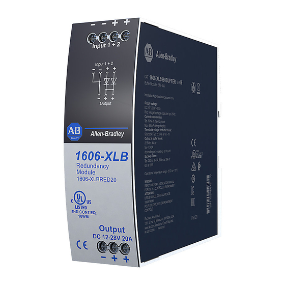
Summary of Contents for Allen-Bradley 1606-XLBRED20
- Page 1 Dual Input Redundancy Module - DC 12…28V, 20 A Catalog Number 1606-XLBRED20 Reference Manual Original Instructions...
- Page 2 Dual Input Redundancy Module - DC 12…28V, 20 A Reference Manual Important User Information Read this document and the documents listed in the additional resources section about installation, configuration, and operation of this equipment before you install, configure, operate, or maintain this product. Users are required to familiarize themselves with installation and wiring instructions in addition to requirements of all applicable codes, laws, and standards.
-
Page 3: Table Of Contents
Table of Contents Terminology and Abbreviations ........5 Product Overview . - Page 4 Notes: Rockwell Automation Publication 1606-RM111A-EN-P - July 2020...
-
Page 5: Terminology And Abbreviations
Terminology and Terms Descriptions Abbreviations A value that is displayed with the AC or DC before the value represents a nominal DC 24V voltage with standard tolerances (usually ±15%) included. For example: DC 12V describes a 12V battery disregarding whether it is full (13.7V) or flat (10V). A value with the unit (V DC) at the end is a momentary value without any additional 24V DC tolerances included. -
Page 6: Product Overview
Product Overview The 1606-XLBRED20 is a redundancy module, which can be used to build 1+1 and N+1 redundant systems. The 1606-XLBRED20 redundancy module has two input channels, which can be connected to power supplies with up to 10 A output current. The module has one output, which can carry nominal currents up to 20 A. -
Page 7: Input And Output Characteristics
26 A together, use an appropriate fuse on the output. Figure 4, the power supplies can be either 1606-XLX120 or 1606-XLX240. The redundancy module is 1606-XLBRED20. Figure 3 - Input to Output Voltage Drop Figure 4 - Test Setup For Voltage Drop Measurements... -
Page 8: Lifetime Expectancy And Mean Time Between Failure
Lifetime Expectancy and The redundancy module has two input channels, which are completely independent from each other. The dual-input redundancy module can be Mean Time Between Failure considered as two single redundancy modules combined in one housing. The only common point is the circuit trace that ties the two separate circuits together at the output. -
Page 9: Functional Diagram
Functional Diagram Figure 6 - Functional Diagram Surge Input 1 Protection Surge Protection Output Surge Input 2 Protection Front Side and User Elements Figure 7 - Front Side User Elements 1 Input terminals for input 1 and input 2 2 Output terminals Two identical (+) poles Rockwell Automation Publication 1606-RM111A-EN-P - July 2020... -
Page 10: Electromagnetic Compatibility
Electromagnetic The redundancy module is suitable for applications in industrial, residential, commercial, and light industrial environments without any restrictions. Compatibility The following table shows electromagnetic compatibility (EMC) immunity according to generic standards EN 61000-6-1 and EN 61000-6-2. Attributes Standards Values Criteria Contact discharge 8 kV... -
Page 11: Environment
Environment Attributes Values Notes -40…+70 °C (-40…+158 °F) Reduce output power above 60 °C (140 °F) Operational temperature Output derating 0.5 A/1 °C (0.5 A/ 1.8 °F) 55…70 °C (140…158 °F), see Figure 8 Storage temperature -40…+85 °C (-40…+185 °F) For storage and transportation 5…95% r.H. -
Page 12: Safety Features
Safety Features Attributes Descriptions Notes Input/output separation no galvanic separation Schottky diode between input and output The output voltage is regarded to be SELV (EN 60950-1) or PELV (EN 60204-1, EN 62477-1, IEC Safety level of output voltage 60364-4-41) if the input voltage fulfills the requirements for a SELV source or PELV source. Class of protection —... -
Page 13: Physical Dimensions And Weight
Physical Dimensions and Weight Attributes Values and Descriptions Width 39 mm (1.54 in.) Height 124 mm (4.88 in.) 124 mm (4.88 in.) Depth The DIN rail height must be added to the unit depth to calculate the total required installation depth. Weight 280 g (0.62 lb) DIN rail... -
Page 14: Using Only One Input Instead Of Both Channels
Using Only One Input You can use only one input instead of both up to a nominal input current of 20 A at 55 °C (131 °F) max ambient temperature. However, it is always Instead of Both Channels recommended to connect both input path in parallel for reduced power losses and voltage drop. -
Page 15: Use In A Tightly Sealed Enclosure
Figure 14. With the Controls 1606-XLBRED20 redundancy module, the power supply for the demanding loads can be used as a redundant source to supply the controls, as shown in Figure 15. This provides a cost-effective solution to get redundant power for a PLC or controller system. -
Page 16: Example: 1+1 Redundancy Up To 10 A
Example: 1+1 Redundancy 1+1 Redundancy up to 10 A requires two 10 A power supplies and one 1606-XLBRED20 redundancy module. Use separate mains systems for each Up To 10 A power supply whenever it is possible. The power supplies in... -
Page 17: Additional Resources
Automation products in a secure system, harden the control system, manage user access, and dispose of equipment. Industrial Components Preventive Maintenance, Enclosures, and Contact Provides a quick reference tool for Allen-Bradley industrial automation controls and Ratings Specifications, publication IC-TD002 assemblies. - Page 18 At the end of life, this equipment should be collected separately from any unsorted municipal waste. Rockwell Automation maintains current product environmental compliance information on its website at rok.auto/pec. Allen-Bradley, expanding human possibility, and Rockwell Automation are trademarks of Rockwell Automation, Inc. Trademarks not belonging to Rockwell Automation are property of their respective companies.


Need help?
Do you have a question about the 1606-XLBRED20 and is the answer not in the manual?
Questions and answers