Allen-Bradley ControlLogix 1756-OX8I Installation Instructions Manual
Ac 10-265v dc 5-150v isolated relay module
Hide thumbs
Also See for ControlLogix 1756-OX8I:
- Installation instructions manual (16 pages) ,
- Installation instructions manual (16 pages)
Table of Contents
Advertisement
ControlLogix AC (10-265V) DC (5-150V) Isolated
Relay Module
Catalog Number 1756-OX8I
To:
Obtain a User Manual
This product also has a user manual (pub. no. 1756-UM058). To view
it, visit www.ab.com/manuals or www.theautomationbookstore.com.
To purchase a manual, you can:
• contact your distributor or Rockwell Automation representative
• visit www.theautomationbookstore.com and place an order
• call 800.963.9548 (USA/Canada) or 001.320.725.1574 (outside
USA/Canada)
Allen-Bradle
Publication
Installation Instructions
See page:
1756-IN513D-EN-P - November 2003
7
7
8
9
10
11
12
12
13
14
14
15
Advertisement
Table of Contents

Related Manuals for Allen-Bradley ControlLogix 1756-OX8I


Summary of Contents for Allen-Bradley ControlLogix 1756-OX8I
-
Page 1: Table Of Contents
Installation Instructions ControlLogix AC (10-265V) DC (5-150V) Isolated Relay Module Catalog Number 1756-OX8I See page: Identify the Module Components Note the Power Requirements Install the Module Key the Module and Removable Terminal Block/Interface Module Wire the Removable Terminal Block Wire the Module Assemble the Removable Terminal Block and the Housing Install the Removable Terminal Block onto the Module Check the Indicators... - Page 2 2 ControlLogix AC (10-265V) DC (5-150V) Isolated Relay Module Important User Information Solid state equipment has operational characteristics differing from those of electromechanical equipment. Safety Guidelines for the Application, Installation and Maintenance of Solid State Controls (Publication SGI-1.1 available from your local Rockwell Automation sales office or online at http://www.ab.com/manuals/gi) describes some important differences between solid state equipment and hard-wired electromechanical devices.
- Page 3 NOTE: See NEMA Standards publication 250 and IEC publication 60529, as applicable, for explanations of the degrees of protection provided by different types of enclosure. Also, see the appropriate sections in this publication, as well as the Allen-Bradley publication 1770-4.1 ("Industrial Automation Wiring and Grounding Guidelines"), for additional installation requirements pertaining to this equipment.
- Page 4 IP54 protection when applied in Class I, Zone 2 environments. • This equipment shall be used within its specified ratings defined by Allen-Bradley. • Provision shall be made to prevent the rated voltage from being exceeded by transient disturbances of more than 40% when applied in Class I, Zone 2 environments.
- Page 5 ControlLogix AC (10-265V) DC (5-150V) Isolated Relay Module 5 North American Hazardous Location Approval The following information applies Informations sur l’utilisation de cet when operating this equipment in équipement en environnements hazardous locations: dangereux: Products marked “CL I, DIV 2, GP A, B, C, Les produits marqués "CL I, DIV 2, GP A, B, C, D"...
- Page 6 6 ControlLogix AC (10-265V) DC (5-150V) Isolated Relay Module The following information applies Informations sur l’utilisation de cet when operating this equipment in équipement en environnements hazardous locations: dangereux: EXPLOSION HAZARD RISQUE D’EXPLOSION AVERTISSEMENT WARNING • Do not disconnect • Couper le courant ou equipment unless s’assurer que power has been...
-
Page 7: Identify The Module Components
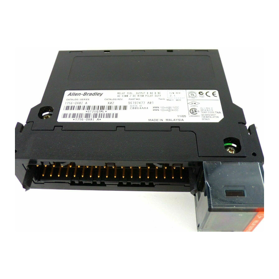
ControlLogix AC (10-265V) DC (5-150V) Isolated Relay Module 7 Identify the Module Components You received the following components with your order: • 1756-OX8I module • Removable Terminal Block (RTB) door label If you did not receive these components, contact your local distributor Rockwell Automation sales office. -
Page 8: Install The Module
8 ControlLogix AC (10-265V) DC (5-150V) Isolated Relay Module Install the Module You can install or remove the module while chassis power is applied. When you insert or remove the module while backplane WARNING power is on, an electrical arc can occur. This could cause an explosion in hazardous location installations. -
Page 9: Key The Module And Removable Terminal Block/Interface Module
ControlLogix AC (10-265V) DC (5-150V) Isolated Relay Module 9 Key the Module and Removable Terminal Block/Interface Module Use the wedge-shaped keying tabs and U-shaped keying bands to prevent connecting the wrong wires to your module. Key positions on the module that correspond to unkeyed positions on the RTB. -
Page 10: Wire The Removable Terminal Block
10 ControlLogix AC (10-265V) DC (5-150V) Isolated Relay Module Wire the Removable Terminal Block Wire the RTB with a 1/8 inch (3.2mm) maximum flat-bladed screwdriver before installing it onto the module. When you connect or disconnect the Removable WARNING Terminal Block (RTB) while field side power is on, an electrical arc can occur. -
Page 11: Wire The Module
ControlLogix AC (10-265V) DC (5-150V) Isolated Relay Module 11 Wire the Module You can only connect wiring to your module with an RTB or IFM. 1756-OX8I Isolated wiring L1-0 OUT-0 N.C. L2-0 L1-0 L1-0 OUT-0 N.O. L1-1 OUT-1 N.C. L1-1 OUT-1 N.O. -
Page 12: Assemble The Removable Terminal Block And The Housing
12 ControlLogix AC (10-265V) DC (5-150V) Isolated Relay Module Assemble the Removable Terminal Block and the Housing 1. Align the grooves at the bottom of the housing with the side edges of the RTB. Groove Side edge of the RTB Groove Strain relief area Side edge of the RTB... -
Page 13: Check The Indicators
ControlLogix AC (10-265V) DC (5-150V) Isolated Relay Module 13 Check the Indicators The indicators show individual I/O status (yellow) for each point and a bi-colored LED for module "OK" (red/green). . RELAY OUTPUT ST 0 1 2 3 4 5 6 7 O 40456-M During power up, an indicator test is done and the following occurs: •... -
Page 14: Remove The Removable Terminal Block From The Module
14 ControlLogix AC (10-265V) DC (5-150V) Isolated Relay Module Remove the Removable Terminal Block from the Module If you need to remove the module, you must remove the RTB first. When you insert or remove the module while backplane WARNING power is on, an electrical arc can occur. -
Page 15: See Specifications
ControlLogix AC (10-265V) DC (5-150V) Isolated Relay Module 15 1756-OX8I Specifications Number of Outputs 8 N.O. & 8 N.C. (2 points/common) Module Location 1756 ControlLogix Chassis Backplane Current 100mA @ 5.1V dc & 100mA @ 24V dc Backplane Power 2.9W Maximum Power Dissipation 3.1W @ 60 (Module) -
Page 16: Publication 1756-In513D-En-P - November
16 ControlLogix AC (10-265V) DC (5-150V) Isolated Relay Module UL/CSA/FM ratings Output rating: C300, R150 Pilot Duty (C300=240V ac, 2.5 A thermal continuous - 7.5A make, 0.75A break @240V ac 50/60Hz.15A make, 1.5A break@120V ac 50/60 Hz 1800VA max make, 180VA max break; R150=1A thermal continuous - 0.22A make/break @ 125V dc 28VA max make/break) Minimum Load Current... - Page 17 ControlLogix AC (10-265V) DC (5-150V) Isolated Relay Module 17 Environmental Conditions Operational Temperature IEC 60068-2-1 (Test Ad, Operating Cold), IEC 60068-2-2 (Test Bd, Operating Dry Heat), IEC 60068-2-14 (Test Nb, Operating Thermal Shock): 0 to 60°C (32 to 140°F) Storage Temperature IEC 60068-2-1 (Test Ab, Un-packaged Non-operating Cold), IEC 60068-2-2 (Test Bb, Un-packaged Non-operating...
- Page 18 18 ControlLogix AC (10-265V) DC (5-150V) Isolated Relay Module Conducted RF Immunity IEC 61000-4-6: 10Vrms with 1kHz sine-wave 80%AM from 150kHz to 80MHz Oscillatory Surge IEEE C37.90.1: Withstand Enclosure Type Rating None (open-style) Certifications: UL Listed Industrial Control Equipment (when product is marked) CSA Certified Process Control Equipment CSA Certified Process Control Equipment for Class I, Division 2 Group A,B,C,D...
- Page 19 ControlLogix AC (10-265V) DC (5-150V) Isolated Relay Module 19 Notes: Allen-Bradle Publication 1756-IN513D-EN-P - November 2003...
- Page 20 Rockwell Automation Support Rockwell Automation provides technical information on the web to assist you in using our products. At http://support.rockwellautomation.com, you can find technical manuals, a knowledge base of FAQs, technical and application notes, sample code and links to software service packs, and a MySupport feature that you can customize to make the best use of these tools.
Need help?
Do you have a question about the ControlLogix 1756-OX8I and is the answer not in the manual?
Questions and answers