Advertisement
Quick Links
-Made in America
Thank you for purchasing this dash panel from Intellitronix. We value our customers!
* Always disconnect the battery before attempting any electrical work on your vehicle.*
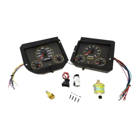
KIT COMPONENTS
◊ Two (2) Assembled Analog Circuit Board
◊ One (1) Temperature Sending Unit (S8013)
* 1/8" NPT, 0-255 Deg., 1/2" NPT Bushing
◊ One (1) Pressure Sending Unit (S8434)
* 1/8" NPT 0-100 PSI Oil Pressure.
◊ One (1) Universal Speedometer Sensor (S9013)
* 7/8" NPT Industry Standard threads
◊ One (1) Mounting Kit
* 4—6/20 Black Oxidized 1" Phillips Head / --4—#6 x 1/4" Spacers
DASHBOARD REMOVAL AND INSTALLATION
Remove the factory gauges from the instrument cluster and insert the digital dash panels. Remove
the protective paper coating from both sides of the acrylic lens. When installing new gauge panels
into the dash, remove the existing OE gauges and back panel. Reuse the original back panel screws
to attach the new panels to the original dash bezel. There are nuts and screws on
each side of the panels, which are used to adjust the spacing between the front and back plate so
the front gauge bezel fits tightly against the factory bezel.
1 – DP5001
INSTALLATION GUIDE
Chevelle Assembled Analog Panel
Part Number: AP5001
Year Series: 1968
Intellitronix
Lifetime Guarantee
(rev. 07/10/2019)
www.intellitronix.com
Advertisement

Related Manuals for Intellitronix AP5001


Summary of Contents for Intellitronix AP5001
- Page 1 -Made in America Lifetime Guarantee Thank you for purchasing this dash panel from Intellitronix. We value our customers! INSTALLATION GUIDE Chevelle Assembled Analog Panel Part Number: AP5001 Year Series: 1968 * Always disconnect the battery before attempting any electrical work on your vehicle.* KIT COMPONENTS ◊...
-
Page 2: Wiring Instructions
Fuel senders reference their ground from the sender mounting plate. Connect the yellow wire to the factory sending unit. 2 – DP5001 Intellitronix www.intellitronix.com (rev. 07/10/2019) - Page 3 When the needle gets to the desired setting, tap the right button once more. It is now set and will enter normal operating mode. To see the high RPM/tach setting, hold down the right button. It will reset after five seconds. 3 – DP5001 Intellitronix www.intellitronix.com (rev. 07/10/2019)
- Page 4 Note: If doing an LS engine swap, pick up the tach signal wire from the ECM/ECU and then set the tach switch to 4-cylinders. You may also need to order the Intellitronix LS Engine Swap Adapter Kit – for Series 1, 2 and 3 engines. The part number is 8014LS. If you are getting the tach signal from the ECU, the resistor in the adapter kit will help pull a stronger signal for the tachometer.
- Page 5 CALIBRATION Note: If using the Intellitronix GPS Sending Unit (not included), the speedometer does not need to be calibrated. The speedometer leaves the factory with an industry standard pre-set setting of 8,000 pulses per mile. Chances are that you may not need to recalibrate your speedometer, unless you have changed the original tire size or the rear end gear ratio.
- Page 6 NOT have received any data and the unit will display ‘Err’ and will revert to the factory settings. At a minimum, drive some distance and return to the start if necessary. If you miss stopping the display at ‘CAL’, simply repeat the steps. Trip Distance 6 – DP5001 Intellitronix www.intellitronix.com (rev. 07/10/2019)
- Page 7 The highest speed measured over multiple runs will be retained in memory. # # # 7 – DP5001 Intellitronix www.intellitronix.com (rev. 07/10/2019)
-
Page 8: Lifetime Guarantee
Made in America Lifetime Guarantee Technical Support Monday – Friday 9am to 5 pm EST (440) 359 7200 support@intellitronix.com FOR QUICK HELP CHECK OUT WEBSIT Q&A PAGE FOR SOME HELP This product carries a limited Lifetime Warranty. 8 – DP5001 Intellitronix www.intellitronix.com... - Page 9 This warranty is limited to replacement or repair of the unit at the discretion of Intellitronix. RETURN POLICY PROCEDURES Return Policy Instructions 1. Download the Intellitronix Return/Repair Form and fill in the information on the form about the product. 2. Place the product being returned in the original packaging that it came in and include a copy of the completed Intellitronix Return/Repair Form.
Need help?
Do you have a question about the AP5001 and is the answer not in the manual?
Questions and answers