Table of Contents
Advertisement
Quick Links
Advertisement
Table of Contents

Related Manuals for GVS H Series


Summary of Contents for GVS H Series
- Page 1 User Manual Indoor Station H Series VDP Indoor Station Manual_V1.1 H-IS32...
-
Page 3: Table Of Contents
Content Chapter 1 Function Review.....................1 Chapter 2 Product Introduction.....................2 2.1 Product Appearance....................2 2.2 Product Dimension.....................3 2.3 Parameter........................3 2.4 Interface Introduction....................4 Chapter 3 Basic Function......................5 3.1 Standby Interface......................5 3.2 Call in..........................7 3.3 Information........................8 3.4 Call..........................9 3.5 Surveillance........................10 3.6 Alarm System Setting.................... -
Page 4: Chapter 1 Function Review
Chapter 1 Function Review This product, based on TCP/IP transmission protocol, is the main device for the H series video door phone system, it supports video phone, defense area setting and picture pushing. Details of the device are as follows: 10.1”... -
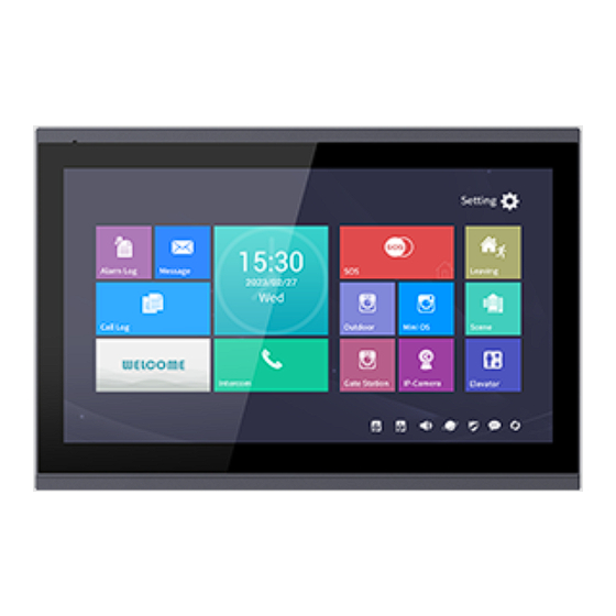
Page 5: Chapter 2 Product Introduction
Chapter 2 Product Introduction 2.1 Product Appearance Speaker Touch Screen... -
Page 6: Product Dimension
2.2 Product Dimension 2.3 Parameter Working Voltage: DC 24V Device Quiescent Current: ≤ 90 mA Device Working Current: ≤ 210 mA Defense Area Output Current: ≤ 200 mA (only when powered separately, defense area output voltage 12V) Screen Size: 10.1 inch Resolution: 1024 ×... -
Page 7: Interface Introduction
2.4 Interface Introduction ① ② ③ Number①: +12V, GND: defense area detector power terminal (current≤200mA). DA/DB: 485 terminals (extension for defense zone and smart home function ). Alarm: alarm output interface (reserved) . Z8: default doorbell function. Z7 to Z1: standard defense area interface, support normal open/close security module. ZX: reserved interface. -
Page 8: Chapter 3 Basic Function
Chapter 3 Basic Function 3.1 Standby Interface Alarm Record Press to check out alarm history and set each defense area. Information Press to check out messages pushed by managercenter. Call Log Press to check, read, delete call history of all types. Call Press to enable a call to either guard unit, other residents or other indoor... - Page 9 Long press for 3 seconds so that an SOS message will be sent to guard unit. Away with Arm/Disarm Mode Press and input the password to enable Away with Arm/Disarm Mode. Smart Home Press to enable smart home scenario control (when smart home system is connected).
-
Page 10: Call In
3.2 Call in Calling Page Basic workflow: ring bell talk unlock call ended Incoming Call: Visitor can call indoor station through outdoor station, the bell of indoor station rings. Resident Press to answer the call. During the call, resident can Press to unlock the gate/door, 5s after unlocking the call will be ended automatically. -
Page 11: Information
3.3 Information Press to enter information page to check messages received from managercenter. Information Page Read Information Choose a message to open and read or delete the message. Message Page... -
Page 12: Call
3.4 Call Press in stand-by page to enter calling page. Calling Page with dial pads Call indoor station Basic workflow: call ring bell talk call ended Call Press to enter indoor station list and call/broadcast to these indoor stations. Input building No., unit No., room No., and Press to confirm to call other residents;... -
Page 13: Surveillance
Talk with guard unit.. Press to end call. 3.5 Surveillance Monitoring page The surveillance includes monitoring outdoor station, mini outdoor station, gate station and IP cameras. Monitor and Unlock Basic workflow: choose monitored device monitor unlock Press in stand-by page to enable surveillance function. Press to unlock for the visitors during the surveillance. -
Page 14: Alarm System Setting
Visitor Call in Surveillance Basic workflow: monitor talk call ended During surveillance to outdoor stations, press to talk with visitor. Community Surveillance Press to start monitoring IP cameras in the community. 3.6 Alarm System Setting Press in stand-by page to enter alarm system setting page. Alarm System Setting page Click to input user password to enable the setting of defense is a property... -
Page 15: Away With Arming/Disarming Mode
Defense area setting status Alarm System Setting In the page of alarm system setting, residents can switch on/off each defense area, choose defense area type and trigger conditions, relevant defense areas types and trigger conditions please refer to Defense Area Wiring. 3.7 Away with Arming/Disarming Mode Press to arm/disarm home. -
Page 16: Chapter 4 System Setting
Chapter 4 System Setting 4.1 Time Setting Press to enter time setting from stand-by page. Time Setting page Time synchronization will allow the indoor station keeping in the same time with PC. 4.2 IP Camera Setting Press in stand-by page to enter IP camera setting. IP Camera Setting page Add or delete the IP cameras to this indoor station. -
Page 17: Call Divert Setting
4.3 Call Divert Setting Press in stand-by page to enter call divert setting page. Call Divert Setting page Choose device type. When the device is indoor station, the target room No. must be typed in. NOTE: When guard unit is chosen, room No. can be vacant. 布防:输入用户密码,随后进入布防延时,需在延时时间内离开防... -
Page 18: Ringtone Setting
Hijack Password Enter (user/default) password enter hijack password enter hijack password again. (hijack password should be set by using user password, they MUST DIFFER). Hijack Password Setting page 4.5 Ringtone Setting Press in stand-by page to enter ringtone setting page. Ringtone Setting page Ringtone Setting Adjust ringtone volume. -
Page 19: Display Setting
Ringtone Choosing Choose a ringtone according to the given list. Ringtone List page NOTE: Other ringtone means the incoming ringtone of guard unit and indoor station . 4.6 Display Setting Press in stand-by page to enter display setting. Display Setting page Adjust screen brightness. -
Page 20: Language Setting
4.7 Language Setting Press in stand-by page to enter language setting. Language Setting page Set the language of the device, language must be set when the device is powered up first time. 4.8 Configuration Setting Press in stand-by page to enter configuration setting, config.password must be typed in. - Page 21 Room No. Setting Set the room number (building, unit etc.). Choose villa if it’s a villa. Config. Password: it’s used to set the number of indoor station, mini outdoor station and to enable factory reset. Default project password is 801801. Mini Outdoor Station Setting Enter setting mode of mini outdoor station.
-
Page 22: Screen Cleaning
4.9 Screen Cleaning Lock the screen to avoid false operation during cleaning the screen. Press , then the popped out window shows a 60s countdown, which allows cleaning to be done, during this countdown the touch will not work. Countdown page NOTE: 1. -
Page 23: Chapter 5 Installation
Chapter 5 Installation 5.1 Installation Height 1.50m Ground Suggestion Installation Height: 1.5m... -
Page 24: Installation Instruction
5.2 Installation Instruction ① Step 1: Aim the bracket screws to the Wall holes on the 86*86 installation box Screw and fasten the bracket. 86x86mm Bracket ② Step 2: Wire the indoor station, then aim the bracket at the bracket holes on the back of the indoor station (as of ②), when all four holes are aimed, lightly push down the monitor... -
Page 25: Chapter 6 Defense Area Wiring
Chapter 6 Defense Area Wiring 6.1 Defense Area Wiring Diagram 6.1.1 Single Security Detector Wiring Indoor Station Z1 to Z7 wiring: Normal open Normal closed Z(1-7) Indoor Station Z8 wiring: Normal open 6.1.2 Multi Security Detectors Wiring Indoor Station Z1 to Z7 wiring: Normal closed Normal closed Normal closed... -
Page 26: Defense Property Instruction
6.2 Defense Property Instruction Defense Trigger Type page 24 hours Instant: This defense area will detect as soon as the system is power on, and it will not be influenced by arming/disarming. Once this defense area is triggered, the alarm warning will be sent out immediately. Delay alarm: After this defense area is armed, once it triggers, then enter the counting down of alarm delay.
Need help?
Do you have a question about the H Series and is the answer not in the manual?
Questions and answers