Table of Contents
Advertisement
Quick Links
Advertisement
Table of Contents

Related Manuals for GVS H Series


Summary of Contents for GVS H Series
- Page 1 User Manual Indoor Station H Series VDP Indoor Monitor Manual_V1.0 H-IS34、35...
-
Page 3: Table Of Contents
Content Chapter 1 Function Review ..................1 Chapter 2 Product Introduction ...................2 2.1 Product Appearance ..................2 2.2 Product Dimension ..................3 2.3 Interface Introduction ..................4 2.4 Parameter ......................5 Chapter 3 Basic Function .....................6 3.1 Standby Interface .....................6 3.2 Call in ........................ 8 3.3 Information ....................... -
Page 4: Chapter 1 Function Review
Chapter 1 Function Review Based on TCP/IP transmission protocol, this product is the main device for the H series video door phone system, it supports video phone intercom, defense area setting and picture pushing. Details of the device are as follows: 7”... -
Page 5: Chapter 2 Product Introduction
Chapter 2 Product Introduction 2.1 Product Appearance... -
Page 6: Product Dimension
2.2 Product Dimension... -
Page 7: Interface Introduction
2.3 Interface Introduction ② ③ ① Number① +12V GND: power supply interface of defense area detectors (the power supply current≤100mA, depending on the actual factory model) Z8: doorbell function as default. Z7 to Z1: standard defense area interface, support normal open/close security module. (Please check Page 26 for setting and the wiring details ) Number②... -
Page 8: Parameter
2.4 Parameter Working Voltage: DC 24V Device Quiescent Current: ≤ 80 mA Device Working Current: ≤ 200 mA Screen Size: 7 inch Resolution: 800 × 480 Appearance Dimension (L × W × D):182 × 119 × 15mm Environment Temp.: -10℃ ~ +55℃ Call Waiting: 30s Call Duration: 120s Surveillance Duration: 30s... -
Page 9: Chapter 3 Basic Function
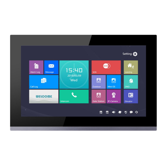
Chapter 3 Basic Function 3.1 Standby Interface Alarm Record Press to check out alarm history and set each defense area. Information Press to check out messages pushed by management center. Call Log Press to check, read, delete call history among Indoor Station, Outdoor Station and Guard Unit. - Page 10 Press to monitor Gate Station. Press to monitor IP cameras. Long press for 2 seconds so that an SOS message will be sent to Guard Unit. Arm/Disarm for Leaving Mode Press and input the password to enable Away with Arm/Disarm Mode. Do Not Disturb Press to turn on the DND function and mute the ringing tone.
-
Page 11: Call In
3.2 Call in Calling Page Basic workflow: ring bell talk unlock call ended Incoming Call: Visitor can call indoor station through outdoor station, the bell of indoor station rings. Resident Press to answer the call. During the call, resident can Press to unlock the gate/door, 5s after unlocking the call will be ended automatically. -
Page 12: Information
Image Capture: 1) During the call, resident can Press to capture images manually. 2) Images captured will be saved in Call Log in stand-by page. Image Captured 3.3 Information Press to enter information page to check messages received from management center. Information Page... -
Page 13: Call
Read Information Choose a message to open and read or delete the message. Message Page 3.4 Call Press in standby page to enter calling page. Calling Page with dial pads... - Page 14 Call Indoor Monitor Basic workflow: call ring bell talk call ended Press to enter indoor monitor list and call/broadcast to exact indoor monitors. Input building No., unit No., room No., and Press to confirm to call other residents; if only room No. is typed in, then the building/unit No. will be considered as default 0.
-
Page 15: Surveillance
3.5 Surveillance Monitor Page The surveillance includes monitoring Outdoor Station, Mini Outdoor Station, Gate Station and IP cameras. Monitor and Unlock Basic workflow: choose monitored device monitor unlock Press icon in stand-by page to enable surveillance function. Press to unlock for the visitors during the surveillance. Press to end surveillance. -
Page 16: Alarm System Setting
Community Surveillance Press to start monitoring IP cameras in the community. 3.6 Alarm System Setting Press in stand-by page to enter alarm system setting page. Alarm System Setting page Click , then input user password to enter the setting of defense area (Default user password: 666666). - Page 17 Alarm System Setting The defense zone is 8 IO zone, resident can set the normally open / normally closed state for each zone. Further instruction of defense zone please refer to Chapter 6 Zone Wiring Instructions. 8IO zone attribute setting interface The 8 IO zone in defense area setting interface is shown in the figure:...
-
Page 18: Arm/Disarm For Leaving Mode
3.7 Arm/Disarm for Leaving Mode Press to arm/disarm for leaving mode. Password Input page Under arming, the user can: Disarm: input the password to disarm. Under disarming, the user can: Arm: type in the password and enter arming delay, leave before the delay time’s up. -
Page 19: Chapter 4 System Setting
Chapter 4 System Setting 4.1 Time Setting Press to enter time setting from stand-by page. Time Setting page Time synchronization will allow the Indoor Station keeping in the same time with PC. 4.2 IP Camera Setting Press in stand-by page to enter IP camera setting. IP Camera Setting page... -
Page 20: Call Divert Setting
Add or delete the IP cameras to this Indoor Monitor. When adding camera, the camera code needs to be typed in. 4.3 Call Divert Setting Press in stand-by page to enter call divert setting page. Call Divert Setting page Choose device type. When select as Indoor Monitor, the target room No. -
Page 21: Password Setting
4.4 Password Setting Press in stand-by page to enter password setting. Password Setting page User Password Input default password input new password confirm (default password: 666666) Hijack Password Enter (user/default) password enter hijack password enter hijack password again. (hijack password should be set in advance by using user password, they MUST DIFFER). -
Page 22: Ringtone Setting
4.5 Ringtone Setting Press in main page to enter ringtone setting page. Ringtone Setting page Ringtone Setting Adjust ringtone volume. Touch tone and fault tone setting. Ringtone Choosing Choose a ringtone per the given list Ringtone List page NOTE: Other ringtone indicates the incoming ringtone of Indoor Monitor, Villa Station and Guard Unit. -
Page 23: Display Setting
4.6 Display Setting Press in main page to enter display setting page. Display Setting page Adjust screen brightness. Set screen saver starting and ending time. 4.7 Language Setting Press in main page to enter language setting page. Language Setting page Language must be chosen when the device is powered up first time. -
Page 24: Mini Outdoor Station Configuration
4.8 Mini Outdoor Station Configuration Press in main page and input user password (666666) to enter mini outdoor station setting interface. Card Management Choose Mini outdoor station 1/ Mini outdoor station 2 Press icon Swipe the + card on the corresponding Mini outdoor station to enter card management interface. Mini Outdoor Station Unlock Time Setting The unlocking time of mini outdoor station 1 / mini outdoor station 2 can be set. -
Page 25: Configuration Setting
4.9 Configuration Setting Press in main page to enter configuration setting, config. password must be typed in. Configuration Setting page Room No. Setting Set the room number (building, unit etc.). Choose villa if it’s for villa scenario. Config. Password: it’s used to set the number of Indoor Monitor, Villa Station and to enable factory reset. -
Page 26: Screen Cleaning
Factory Reset Press factory reset to set the device to the factory reset version. NOTE: 1. Reset after powered for 30s, the device will be reset to factory version. 2. Reset within powered for 30s, the device will be reset to factory version, meanwhile all the history will be CLEANED. -
Page 27: Chapter 5 Installation
Chapter 5 Installation 5.1 Installation height Ground Suggestion Installation Height: 1.5m... -
Page 28: Installation Instruction
5.2 Installation Instruction ① Step 1: Aim the bracket screws to the holes on the 86*86 installation box and fasten the bracket. Bracket 86x86mm Screw Wall ② Step 2: Wire the indoor station, then aim the bracket at the bracket holes on the back of the indoor station (as of ②), when all four holes are aimed, lightly... -
Page 29: Chapter 6 Defense Area Wiring
Chapter 6 Defense Area Wiring In the interface of defense zone property setting, check the I/O Mode zone to set it as I/O mode. 6.1 Defense Area Wiring Diagram 6.1.1 Single Security Detector Wiring If the I/O mode zone corresponding frame is checked, Z1-Z8 Indoor monitor Z1-Z8 wiring:... -
Page 30: Defense Property Instruction
6.2 Defense Property Instruction Defense Trigger Type page Instant alarm: After this defense area is armed, once it triggers, the alarm warning will be sent out immediately. Delay alarm: After this defense area is armed, once it triggers, then enter the counting down of alarm delay.
Need help?
Do you have a question about the H Series and is the answer not in the manual?
Questions and answers