GVS T Series User Manual
Hide thumbs
Also See for T Series:
- User manual (42 pages) ,
- User manual (17 pages) ,
- User manual (2 pages)

Related Manuals for GVS T Series


Summary of Contents for GVS T Series
- Page 1 User Manual Outdoor Station T - series Keypad Outdoor Station User Manual_V1.0 T-OS07...
-
Page 3: Table Of Contents
Contents Unit 1 Overview......................1 1.1 Functions and Characteristics..............1 1.2 Parameters......................1 Unit 2 Appearance and Interface................2 2.1 Appearance....................... 2 2.2 Dimension......................3 2.3 Interface Introduction..................4 Unit 3 Installation....................... 5 3.1 Installation Height................... 5 3.2 Installation Steps..................... 6 3.3 System Wiring....................7 Unit 4 Operation Instructions................. -
Page 4: Unit 1 Overview
Unit 1 Overview This product is an Outdoor Station of 2-Wire analog video door phone system, it makes communication with Indoor Monitor via 2-core cable in the system, the Outdoor Station also supports access control with IC card. 1.1 Functions and Characteristics Support video intercom and unlocking ... -
Page 5: Unit 2 Appearance And Interface
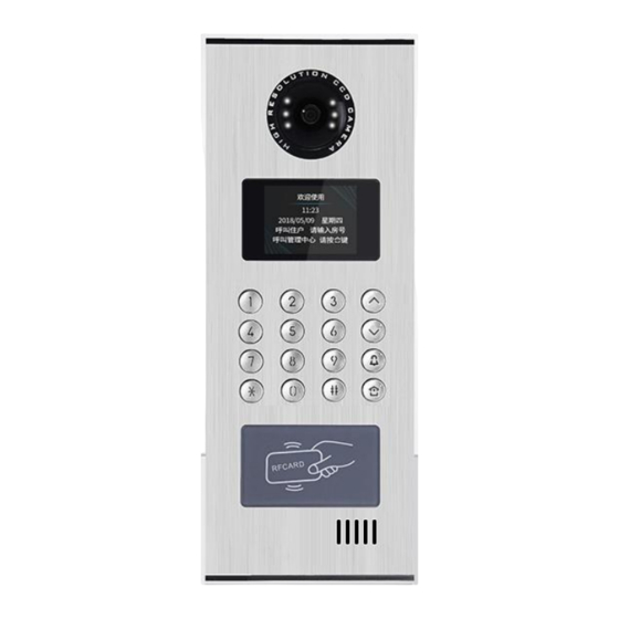
Unit 2 Appearance and Interface 2.1 Appearance Front View Rear View Aluminium Panel Camera Fill-in Light Display Area Keyped Area Wire Connecting Area Card Reading Area Speaker... -
Page 6: Dimension
2.2 Dimension... -
Page 7: Interface Introduction
2.3 Interface Introduction ① ② ② ③ ④ ⑤ ① Network(update) Interface (1: TX+ , 2: TX-, 3: RX+, 4: RX-); ② External camera input; ③ Wiegand output; ④ BUS-A 、BUS-B:2-Wire BUS interface; NO, COM, NC: Normally open pin, Common pin, Normally closed pin; GS: Door status detection;... -
Page 8: Unit 3 Installation
Unit 3 Installation 3.1 Installation Height Ground Suggested height for installation: camera is 1.6m above the ground... -
Page 9: Installation Steps
3.2 Installation Steps Step 1: Put the embedded box into the preformed groove (as Pic.2). After getting the cable out through the opening, fasten the box with screws or by cement. Dimensions of embedded box are as below: 预埋盒尺寸(W/H/D):如图 1 所示 Pic.1 Pic.2 Step 2: After connecting the cable to the Outdoor Station (as Pic.3), match the snap... -
Page 10: System Wiring
3.3 System Wiring Remarks: This Outdoor Station is using keypad to make the call, which is suitable for large system with max. 128 apartments, the wiring topology is shown as above. In addition, it also supports being installed for villa or other small system. Support multiple Indoor Monitors(Max. - Page 11 Restricted by the power consumption, the system only allows 2 Indoor Monitors showing the screen (being operated) at the same time (intercom function is not affected). Distributor is recommended for system wiring (star topology), while Bus topology (hand in hand connection) is supported as well. Wiring distance A is the Max.
-
Page 12: Unit 4 Operation Instructions
Unit 4 Operation Instructions 4.1 Call By Apartment No. In standby mode, visitors can input apartment No. and press “ ” to make the call, and the device will enter calling interface. If Indoor Monitor is offline, it will go back to the standby interface with “Beep”. If Indoor Monitor is online, it will begin the calling count down and start to play the ringback. -
Page 13: Call Guard Unit
4.3 Call Guard Unit In standby mode, visitors can press to call Guard Unit. 4.4 Unlock 1) Unlock By Swiping Card Swipe the registered card to the card reading area to unlock the door, and Outdoor Station will show “door opened”. 2) Unlock By Indoor Monitor Residents can unlock the door from Indoor Monitor when Outdoor Station is calling or being monitored by Indoor Monitor, and Outdoor Station will show “door opened”. -
Page 14: Unit 5 Settings
5) User Password Unlock If User Password Unlock function is activated, residents can press “ ” and wait for 1S to enter user password interface. User Password Unlock Interface In User Password interface, input Apartment No. and related password, then press “ ”... -
Page 15: Main Setting Interface
5.2 Main Setting Interface After inputting the correct configuration password and “ ”, main setting interface is ↑↓ shown as below, users can press “ ” to choose the item. Main Setting Interface Unit 6 System Settings System setting includes setting of Time, Volume, Language, PIN, Unlock Time, Card ↑↓... -
Page 16: Time Setting
6.1 Time Setting ↑↓ Time setting interface is shown as below, users can press “ ” to select each option and input the number, press “ ” to delete or return. After revising finished , press “ ” to save and return. Time Setting Interface 6.2 Volume Setting Volume setting interface is shown as below, users can press ”... -
Page 17: Language Setting
6.3 Language Setting ↑↓ Language setting interface is shown as below, users can press “ ” to select the language, press “ ” to save and return. Language Setting Interface 6.4 PIN Setting Password setting includes 3 items: On and Off for user password and public password, and change of public password. -
Page 18: Unlocked-Time Setting
6.5 Unlocked-Time Setting Unlocked-time setting is to set the duration of the unlocked time after door opened. When the time is out, the door will lock again automatically. The unit is "second". Press " " key to delete and press " "... - Page 19 Users can enter ”check(card information) ” to check all card numbers and the quantity of registered cards. ↑↓ Press ” ” to page up/down the card numbers. Card Information Interface If you choose the“clear”, a message will come out for you to confirm the operation(delete all).
-
Page 20: Unit 7 Configuration Settings
Unit 7 Configuration Settings Configuration setting includes address setting, alarm setting, factory testing, project pin, ↑↓ company info and device info. Press “ ” to enter a particular setting. Configuration Setting Interface 1 Configuration Setting Interface 2 7.1 Address Setting Address setting interface is shown as below, address range: 1~32. -
Page 21: Alarm Setting
7.2 Alarm Setting Alarm Setting interface is shown as below, users can press “ ” to turn on/off each alarm option. For “Door alarm”, if the door is unlocked over 120s, the device will ring the alarm until the door is locked again. Alarm Setting Interface 7.3 Factory Testing There are various testing programs on factory testing interface, most frequently... -
Page 22: Configuration Password
7.4 Configuration Password To change the configuration password: input the current password, move to new password if the current password you input is correct, then input your new password(6 digit) twice. Configuration Password Interface 7.5 Device Information In device information interface you can find the version of the device(MAIN/MCU), IP address and MAC address.
Need help?
Do you have a question about the T Series and is the answer not in the manual?
Questions and answers