
Related Manuals for GVS S Series


Summary of Contents for GVS S Series
- Page 1 User Manual Mini Outdoor Station S Series Digital System Mini Outdoor Station User Manual_V1.0 Model No.: SO001...
-
Page 3: Table Of Contents
CONTENTS Chapter 1 Product Introduction ..................1 1.1. Function ......................1 1.2. Parameter ......................2 Chapter 2 Product Introduction ..................3 2.1. Front View ......................3 2.2. Back View ......................4 Chapter 3 Installation ....................5 3.1. Installation Steps ..................... 5 3.2. Installation Height .................... 6 3.3. -
Page 4: Chapter 1 Product Introduction
Product Introduction Chapter 1 This product is the mini outdoor stations of the S series Digital system VDP. By using standard CAT5 cables, it makes visual intercom call to indoor monitor and guard station possible. Besides, it supports IC access control. -
Page 5: Parameter
1.2.Parameter Working Parameter Working voltage: DC 24V/PoE 48V Static Current: ≤ 75mA/PoE 48V Working Current: ≤ 300mA/DC12~24V Working Temperature: -20 ℃ ~70 ℃ Storage Temperature: -40 ℃ ~70 ℃ Dimension(W/H/D): 120 × 194 × 44.7mm Camera Type: CMOS Pixel: 2 MP View Angle: Diagonal 95°... -
Page 6: Chapter 2 Product Introduction
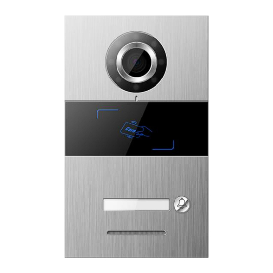
Product Introduction Chapter 2 2.1. Front View Camera Fill-in Light Card Reading Area Name Tag Call Button Speaker... -
Page 7: Back View
2.2. Back View Interface Description: RJ45 Network Interface : cable interface, connecting standard 48V POE switch GND +24V : independent DC 24V power supply interface UNL GND : Door inside unlock interface GS GND : door status detection interface NO COM NC : normal open/close interface EL GND :... -
Page 8: Chapter 3 Installation
Installation Chapter 3 3.1.Installation Steps Embedded box dimension ( W/H/D ) : 100.6 × 175.5 × 39mm Step 1: Embedded box slot on the wall. Step 2: Fix the embedded box into the slot, and fasten with screws. Holder Wall Embedded Screw... -
Page 9: Installation Height
3.2.Installation Height Recommended Installation Height: camera is 1.6m above the ground... -
Page 10: Wiring Diagrams
3.3. Wiring Diagrams Wiring for Signal Unlock Mode Wiring for normally closed type lock(Magnetic Lock) Wiring for normally open type lock(Electronic lock) Note: If device is used for power supply under signal unlock mode, the device can only be powered by extra power supply. At the mean time, lock input... - Page 11 Wiring for Exit Button Unlock Mode Exit Button Note: The wiring has no polarity. Wiring for Door Status Alarm Normal Closed Type Note: The door status alarm function can be switched off in two ways. 1. Grounding GS port of the host. 2.
-
Page 12: Chapter 4 Operation Instructions
Operation Instructions Chapter 4 4.1. Calling Indoor Station/ Management Center Prerequisite: In the configuration tool, set the called party. The user presses the button for a long time/short time, and the mini outdoor device will call the Indoor Monitor/ Guard Unit according to the settings in the configuration tool, and ring back. - Page 13 which residents inside can just press and unlock, then create the unlock record. Management Center unlock After setting correctly in the management center, click the unlock button for all, and enter the user password to unlock the mini outdoor station, then generate an unlock record at the same time.
-
Page 14: Chapter 5 Configuration
Configuration Chapter 5 Operation steps of the mini outdoor station configuration tool: 1. Run the "WpfAppUpdate" program as an administrator. 2. Switch language. 3. Select the device type as "SO001". Enter the Access password as "801801". Click "Search Equipment" to view the corresponding IP address according to the MAC address of the device. -
Page 15: Device Name
configured are in the same network segment. 5.1.Device Name The device name can be modified. If the SIP account information in the address book is required, the device name needs to be set to the device name corresponding to the account information in the address book. -
Page 16: Sip Account Setting
5.2.SIP Account Setting Local user name: Enter user name, configure the local SIP account, for dial-up calls. Note: Cannot be duplicated with other usernames under the same network. Local SIP account: Display the local SIP account is generated by the local user name and IP address, for call accounts under the same network. -
Page 17: Contact Setting
5.3.Contact Setting 5.3.1. Call Setting Configure the called party for the button on the single outdoor unit. Click < address book selection > button, In the pop-up window, select the contact as the short/long pressed called party, each button has a maximum of 8 contact. - Page 18 5.3.2. Contacts List Display information about the current contact. Contacts include: Network devices discovered after automatic configuration is enabled 、 Address book Imported devices and manually added devices. Add: add contacts on the local device by entering the remarks and SIP account. ...
-
Page 19: Card Management
5.4.Card Management 5.4.1. Card Management Use this configuration tool to register 、 modify 、 delete and empty the card information for local device. Under the default server or custom server mode, the local card data is automatically synchronized with the platform. The maximum storage capacity of access cards is 20,000 cards. - Page 20 swiping card registration operation. Modification: Click the modify button in the action bar, to modify the information about access card. Deletion: Click the delete button in the action bar, to delete the corresponding access card, and the access card will lose the unlocking permission. Empty: Empty the data of resident cards and administrator cards of the device.
-
Page 21: Unlocking Management
5.5.Unlocking management 5.5.1. Unlocking Records Used to view the unlocking record of the device. - Page 22 5.5.2. Unlocking Setting Unlocking time: Support modify the duration of unlocking , automatically closes the door after timeout. The value ranges from 1-30 second. Lock 1 / Lock 2 DTMF unlock password : Set the unlock password of Lock 1 / Lock 2 DTMF, Lock 1 default password is 666666, Lock 2 default password is 888888.
-
Page 23: Alarm Setting
5.6.Alarm Setting ( 1 ) Tamper alarm: When this is enabled, If the device is removed by external force, the device will sound an alarm tone. ( 2 ) Disconnected alarm: When this is enabled, If the device is disconnected, the device will sound an alarm tone, and the status bar displays the disconnected icon. -
Page 24: Network Setting
5.7.Network Setting Automatic configuration mode: When this is enabled, the local device can discover other S-series devices in the same network segment. DHCP: Need manually configure the network after closed, enter IP address 、 subnet mask 、 gateway 、 DNS . -
Page 25: Time Setting
5.8.Time Setting Refresh: The local time can be refreshed. After the NTP server and time zone are modified, need to click save, then click refresh, the device can get the updated time. NTP server setup: Enter server address, enable the device to obtain the accurate clock time from the NTP server address set. -
Page 26: Video Setting
5.9.Video Setting Support to set the video bit rate during the call and monitoring. 5.10. Cloud Server Setting Default server /Custom server Upload the registered face and access card data to the server,and synchronize the data download from the server. When switching to no server mode, you can choose whether to retain server data. - Page 27 Stand-alone mode, the face and access card data registered on the machine are saved locally. When switching to a default server or a custom server, can select whether to upload local data. If choose upload,then upload the local data to the server and synchronize server data;...
-
Page 28: Community Identification Code
5.11. Community Identification Code In default server or custom server mode, the local machine can be bound to the corresponding community by entering the community identification code. 5.12. Login Password Change Login Password can be changed . -
Page 29: About
5.13. About Used to view device related information, including: device name, software version, MCU version, LAN, subnet mask, gateway, DNS, MAC address, cloud intercom server, device management center, and device SIP account information.
Need help?
Do you have a question about the S Series and is the answer not in the manual?
Questions and answers