
Subscribe to Our Youtube Channel
Related Manuals for Planet Networking & Communication XGS-6320 Series


Summary of Contents for Planet Networking & Communication XGS-6320 Series
- Page 1 User’s Manual of XGS-6320 Managed Switches Layer 3 10 Gigabit Managed Ethernet Switch XGS-6320 Switch Series...
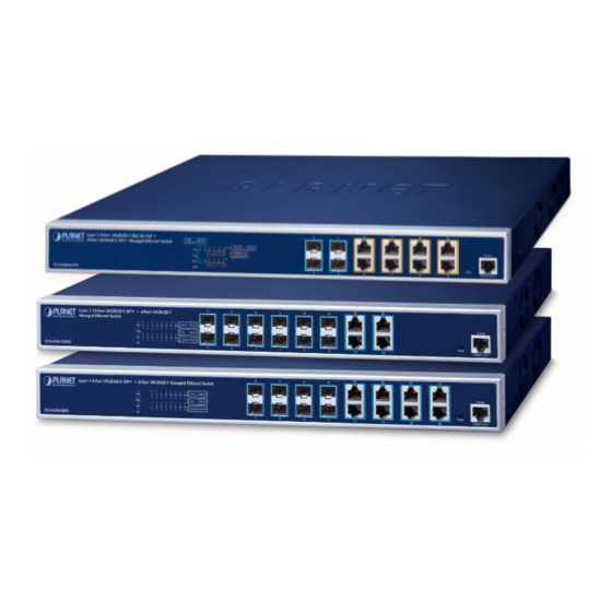
- Page 2 Do not dispose of WEEE as unsorted municipal waste and have to collect such WEEE separately. Revision PLANET XGS-6320 Series User's Manual Models: XGS-6320-8X8TR, XGS-6320-12X4TR, XGS-6320-8UP4X Revision: 1.1 (Jan., 2024)
-
Page 3: Table Of Contents
User’s Manual of XGS-6320 Managed Switches TABLE OF CONTENTS 1. INTRODUCTION ........................13 1.1 Packet Contents ............................13 1.2 Product Description ........................... 13 1.3 Product Features ............................17 1.4 Product Specifications ..........................20 2. INSTALLATION ........................26 2.1 Hardware Description ..........................26 2.1.1 Switch Front Panel .............................. - Page 4 User’s Manual of XGS-6320 Managed Switches 4.2.1.4 ARP ................................52 4.2.1.5 Users Configuration ........................... 53 4.2.1.6 Privilege Levels ............................55 4.2.1.7 NTP Configuration ............................. 57 4.2.1.8 Time Configuration ............................ 58 4.2.1.9 UPnP ................................. 60 4.2.1.10 CPU Load ..............................61 4.2.1.11 System Log .............................. 62 4.2.1.12 Detailed Log ............................
- Page 5 User’s Manual of XGS-6320 Managed Switches 4.2.5.5 Binding ..............................98 4.2.5.6 Declined IP ..............................99 4.2.6 Remote Management ............................100 4.2.6.1 Remote NMS Configuration ........................100 4.3 Switching ..............................102 4.3.1 Port Management .............................. 102 4.3.1.1 Port Configuration ........................... 102 4.3.1.2 Port Statistics Overview ...........................
- Page 6 User’s Manual of XGS-6320 Managed Switches 4.3.7.3 Protocol-based VLAN ..........................147 4.3.7.4 Protocol-based VLAN Membership ......................149 4.3.8 GVRP ................................150 4.3.8.1 GVRP Configuration ..........................151 4.3.8.2 GVRP Port Configuration ........................152 4.3.9 MRP .................................. 153 4.3.9.1 Port Configuration ........................... 153 4.3.9.2 MVRP Global Configuration ........................
- Page 7 User’s Manual of XGS-6320 Managed Switches 4.3.14 LLDP ................................203 4.3.14.1 Link Layer Discovery Protocol ....................... 203 4.3.14.2 LLDP Configuration ..........................203 4.3.14.3 LLDP Neighbor ............................206 4.3.14.4 LLDP MED Configuration ........................207 4.3.14.5 LLDP-MED Neighbor ..........................215 4.3.14.6 Port Statistics ............................219 4.3.15 MAC Address Table ............................
- Page 8 User’s Manual of XGS-6320 Managed Switches 4.4.4 IPv6 Routing Info. Base ............................. 263 4.4.5 OSPF ................................. 264 4.4.5.1 Global Configuration ..........................265 4.4.5.2 Network Area ............................266 4.4.5.3 Passive Interface ............................. 268 4.4.5.4 Stub Area ..............................269 4.4.5.5 Area Authentication ..........................270 4.4.5.6 Area Range .............................
- Page 9 User’s Manual of XGS-6320 Managed Switches 4.4.10.4 InterArea Prefix ............................. 304 4.4.10.5 InterArea Router ............................ 305 4.4.11 RIP ................................... 306 4.4.11.1 Global Configuration ..........................306 4.4.11.2 Network Configuration ........................... 308 4.4.11.3 Neighbors Configuration ........................309 4.4.11.4 Passive Interface Configuration ......................310 4.4.11.5 Offset-list Configuration .........................
- Page 10 User’s Manual of XGS-6320 Managed Switches 4.6 Security ..............................343 4.6.1 Access Security ..............................343 4.6.1.1 Authentication Method ..........................343 4.6.1.2 Access Management ..........................346 4.6.1.3 Access Management Statistics ........................ 347 4.6.1.4 SSH ................................. 348 4.6.1.5 HTTPs ..............................349 4.6.2 AAA ................................... 351 4.6.2.1 RADIUS ..............................
- Page 11 User’s Manual of XGS-6320 Managed Switches 4.6.10.2 VLAN Configuration ..........................407 4.6.10.3 ARP Inspection Static Table........................408 4.6.10.4 Dynamic ARP Inspection Table ......................409 4.7 Ring ................................410 4.7.1 Ring Wizard ............................... 410 4.7.2 ERPS ................................. 414 4.7.3 ERPS Status ..............................416 4.7.4 APS ...................................
- Page 12 User’s Manual of XGS-6320 Managed Switches 5. SWITCH OPERATION ....................... 448 5.1 Address Table ............................448 5.2 Learning ..............................448 5.3 Forwarding & Filtering ..........................448 5.4 Store-and-Forward ........................... 449 5.5 Auto-Negotiation ............................449 6. TROUBLESHOOTING ....................... 450 APPENDIX A: Networking Connection ................451 A.1 Switch's Data RJ45 Pin Assignments - 1000Mbps, 1000BASE-T ............
-
Page 13: Introduction
1.2 Product Description Perfect Managed All-port 10Gbps Switch with L3/L2 Switching and Security XGS-6320 series PLANET is a fully-managed all-port 10Gbps Ethernet switch designed for the demand of high-bandwidth required network equipment, such as Wi-Fi 6/6E wireless AP, NAS, workstation and those with 10Gbps fiber or copper interfaces. - Page 14 10GBASE-T and 10GBASE-X SFP Dual Media Interfaces for Diversified Bandwidth Applications PLANET XGS-6320 series has the capability to reach a high speed of 10Gbps over copper or fiber-optic cabling which helps to accelerate the performance of large data transmission. The built-in 10GBASE-T copper interfaces support 5-speed (10G/5G/2.5G/1G/100) auto-negotiation, and 10Gbps data transmission with the existing Cat6A/Cat7 UTP cabling, meaning the...
- Page 15 AC and DC Redundant Power to Ensure Continuous Operation (excluding XGS-6320-8UP4X) The XGS-6320 series is equipped with one 100~240V AC power supply unit and one additional 36-60V DC power supply unit for redundant power supply. A redundant power system is also provided to enhance the reliability with either AC or DC power supply unit.
- Page 16 Powerful Network Security The XGS-6320 series offers comprehensive Layer 2 to Layer 4 access control list (ACL) for enforcing security to the edge. It can be used to restrict network access by denying packets based on source and destination IP address, TCP/UDP port number or defined typical network applications.
-
Page 17: Product Features
User’s Manual of XGS-6320 Managed Switches 1.3 Product Features Physical Port XGS-6320-8UP4X - Eight 10GBASE-T RJ45 ports, backward compatible with 100/1G/2.5G/5GBASE-T auto-negotiation and supports IEEE802.3bt PoE++ standard - Four 10GBASE-X SFP+ ports, backward compatible with 100BASE-FX, 1000BASE-X and 2500BASE-X SFP transceivers ... - Page 18 User’s Manual of XGS-6320 Managed Switches Layer 3 IP Routing Features IPv4 dynamic routing protocol supports RIPv2 and OSPFv2 and IPv6 OSPFv3 IPv6 dynamic routing protocol supports OSPFv3 IPv4/IPv6 hardware static routing Routing interface provides per VLAN routing mode ...
- Page 19 User’s Manual of XGS-6320 Managed Switches IPv4 IGMP Snooping port filtering IPv6 MLD Snooping port filtering Multicast VLAN Registration (MVR) support Security Authentication IEEE 802.1x Port-based/MAC-based network access authentication Built-in RADIUS client to co-operate with the RADIUS servers TACACS+ login users access authentication RADIUS/TACACS+ users access authentication Guest VLAN assigns clients to a restricted VLAN with limited services...
-
Page 20: Product Specifications
User’s Manual of XGS-6320 Managed Switches 1.4 Product Specifications Product XGS-6320-8T8XR XGS-6320-12X4TR XGS-6320-8UP4X Hardware Specifications 8 10GBASE-T RJ45 auto 4 10GBASE-T RJ45 auto 8 10GBASE-T RJ45 auto negotiation negotiation ports (Ports 9 to negotiation ports (Ports 13 ports (Ports 5 to 12) to 16) Copper Ports Supports... - Page 21 User’s Manual of XGS-6320 Managed Switches Low Speed: Controller temperature < 70 degrees C - Low Speed: PoE Usage < 50% High Speed: Controller temperature > 75 degrees C - High Speed: PoE Usage > 60% System: System: AC (Green), DC (Green), Ring (Green), Ring Owner PWR (Green), SYS (Green), Ring (Green) (Green), Ring Owner (Green)
- Page 22 User’s Manual of XGS-6320 Managed Switches Mid-span: 4/5(+), 7/8(-) PoE Power Budget 420W maximum Max. Number of Type 2 Max. Number of Type 3 Max. Number of Type 4 PoE Management Functions Active PoE Device Detection PoE Power Recycling Yes, daily or predefined schedule PoE Schedule 4 schedule profiles PoE Extend Mode...
- Page 23 User’s Manual of XGS-6320 Managed Switches Flow Control disable/enable Display each port’s speed duplex mode, link status, flow control status, auto negotiation status, Port Status trunk status TX/RX/Both Port Mirroring Many-to-1 monitor Supports up to 5 sessions IEEE 802.1Q tag-based VLAN, IEEE 802.1ad Q-in-Q tunneling Private VLAN Edge (PVE), up to 9 VLAN groups MAC-based VLAN...
- Page 24 User’s Manual of XGS-6320 Managed Switches - Port number - 802.1p priority - 802.1Q VLAN tag - DSCP/TOS field in IP packet Security Functions IP-based ACL/MAC-based ACL ACL based on: - MAC Address - IP Address - Ethertype Access Control List - Protocol Type - VLAN ID - DSCP...
- Page 25 User’s Manual of XGS-6320 Managed Switches Remote Syslog System log LLDP protocol PLANET Smart Discovery Utility PLANET CloudViewerPro app Remote Syslog Event Management System log SMTP RFC1213 MIB-II RFC 2863 IF-MIB RFC1643 Ethernet MIB RFC2863 Interface MIB RFC2665 Ether-Like MIB RFC2737 Entity MIB SNMP MIBs RFC2819 RMON MIB (Groups 1, 2, 3 and 9)
-
Page 26: Installation
User’s Manual of XGS-6320 Managed Switches 2. INSTALLATION This section describes the hardware features and installation of the Managed Switch on the desktop or rack mount. For easier management and control of the Managed Switch, familiarize yourself with its display indicators, and ports. Front panel illustrations in this chapter display the unit LED indicators. - Page 27 User’s Manual of XGS-6320 Managed Switches ■ 10 Gigabit TP interface 100/1G/2.5G/10G BASE-T Copper, RJ45 twisted-pair: Up to 100 meters ■ IEEE 802.3bt TP interface (Only for XGS-6320-8UP4X) 802.3bt PoE++ injector function which is capable of delivering 95W PoE power per port ■...
-
Page 28: Led Indications
User’s Manual of XGS-6320 Managed Switches 2.1.2 LED Indications The front panel LEDs indicate instant statuses of power and system, ring, port links and data activity; they help monitor and troubleshoot when needed. Figures 2-1-2-1, 2-1-2-2 2-1-2-3 show the LED indications of the Managed Switches. XGS-6320-8UP4X Front Panel Figure 2-1-2-1: Front Panel of XGS-6320-8UP4X XGS-6320-8X8TR LED Indication... - Page 29 User’s Manual of XGS-6320 Managed Switches 10GBASE-T Ports (Ports 9 to 16 or Ports 13 to 16): Color Function Lights: To indicate the port is running at 1000Mbps or 2500Mbps. 1G/2.5G Green LNK/ACT Blinks: To indicate that the switch is actively sending or receiving data over that port. To indicate the port is running at 10GMbps and successfully Amber Lights:...
-
Page 30: Switch Rear Panel
User’s Manual of XGS-6320 Managed Switches 2.1.3 Switch Rear Panel The rear panel of the Managed Switch consists of the AC inlet power socket. Figures 2-1-3-1and 2-1-3-2 show the rear panels of the Managed Switches. XGS-6320-8X8TR and XGS-6320-12X4TR Rear Panel Figure 2-1-3-1: Rear Panel of XGS-6320-8X8TR / XGS-6320-12X4TR XGS-6320-8UP4X Rear Panel Figure 2-1-3-2: Rear Panel of XGS-6320-8UP4X... -
Page 31: Desktop Installation
User’s Manual of XGS-6320 Managed Switches 2.2.1 Desktop Installation To install the Managed Switch on desktop or shelf, please follow these steps: Step 1: Attach the rubber feet to the recessed areas on the bottom of the Managed Switch. Step 2: Place the Managed Switch on the desktop or the shelf near an AC power source, as shown in Figure 2-2-1. Figure 2-2-1: Place the Managed Switch on the Desktop Step 3: Keep enough ventilation space between the Managed Switch and the surrounding objects. -
Page 32: Rack Mounting
User’s Manual of XGS-6320 Managed Switches 2.2.2 Rack Mounting To install the Managed Switch in a 19-inch standard rack, please follow the instructions described below. Step 1: Place the Managed Switch on a hard flat surface, with the front panel positioned towards the front side. Step 2: Attach the rack-mount bracket to each side of the Managed Switch with supplied screws attached to the package. -
Page 33: Installing The Sfp/Sfp+ Transceiver
User’s Manual of XGS-6320 Managed Switches 2.2.3 Installing the SFP/SFP+ Transceiver The sections describe how to insert an SFP/SFP+ transceiver into an SFP/SFP+ slot. The SFP/SFP+ transceivers are hot-pluggable and hot-swappable. You can plug in and out the transceiver to/from any SFP/SFP+ port without having to power down the Managed Switch, as Figure 2-2-4 shows.. - Page 34 User’s Manual of XGS-6320 Managed Switches Fast Ethernet Transceiver (100BASE-BX, Single Fiber Bi-directional SFP) Model Speed (Mbps) Connector Interface Fiber Mode Distance Wavelength (TX/RX) Operating Temp. MFB-FA20 WDM(LC) Single Mode 20km 1310nm/1550nm 0 ~ 60 degrees C MFB-FB20 WDM(LC) Single Mode 20km 1550nm/1310nm 0 ~ 60 degrees C...
- Page 35 User’s Manual of XGS-6320 Managed Switches -40 ~ 85 ℃ MGB-TLA40 1000 WDM(LC) Single Mode 40km 1310nm 1550nm -40 ~ 85 ℃ MGB-TLB40 1000 WDM(LC) Single Mode 40km 1550nm 1310nm -40 ~ 85 ℃ MGB-TLA80 1000 WDM(LC) Single Mode 80km 1490nm 1550nm -40 ~ 85 ℃...
- Page 36 User’s Manual of XGS-6320 Managed Switches Connecting the Fiber Cable Insert the duplex LC connector into the SFP/SFP+ transceiver. Connect the other end of the cable to a device with SFP/SFP+ transceiver installed. Check the LNK/ACT LED of the SFP/SFP+ slot on the front of the Managed Switch. Ensure that the SFP/SFP+ transceiver is operating correctly.
-
Page 37: Switch Management
User’s Manual of XGS-6320 Managed Switches 3. SWITCH MANAGEMENT This chapter explains the methods that you can use to configure management access to the Managed Switch. It describes the types of management applications and the communication and management protocols that deliver data between your management device (workstation or personal computer) and the system. -
Page 38: Management Access Overview
User’s Manual of XGS-6320 Managed Switches 3.2 Management Access Overview The Managed Switch gives you the flexibility to access and manage it using any or all of the following methods: An administration console Web browser interface An external SNMP-based network management application The administration console and Web browser interface support are embedded in the Managed Switch software and are available for immediate use. -
Page 39: Administration Console
User’s Manual of XGS-6320 Managed Switches 3.3 Administration Console The administration console is an internal, character-oriented, and command line user interface for performing system administration such as displaying statistics or changing option settings. Using this method, you can view the administration console from a terminal, personal computer, Apple Macintosh, or workstation connected to the Managed Switch's console (serial) port. -
Page 40: Web Management
User’s Manual of XGS-6320 Managed Switches 3.4 Web Management The Managed Switch offers management features that allow users to manage the Managed Switch from anywhere on the network through a standard browser such as Google Chrome. After you set up your IP address for the switch, you can access the Managed Switch's Web interface applications directly in your Web browser by entering the IP address of the Managed Switch. -
Page 41: Snmp-Based Network Management
User’s Manual of XGS-6320 Managed Switches 3.5 SNMP-based Network Management You can use an external SNMP-based application to configure and manage the Managed Switch, such as SNMP Network Manager, HP Openview Network Node Management (NNM) or What’s Up Gold. This management method requires the SNMP agent on the switch and the SNMP Network Management Station to use the same community string. - Page 42 User’s Manual of XGS-6320 Managed Switches Press the “Refresh” button for the currently connected devices in the discovery list as the screen shows below: Figure 3-1-7: Planet Smart Discovery Utility Screen This utility shows all necessary information from the devices, such as MAC address, device name, firmware version, and device IP subnet address.
-
Page 43: Web Configuration
User’s Manual of XGS-6320 Managed Switches 4. WEB CONFIGURATION This section introduces the configuration and functions of the Web-based management from Managed Switch. About Web-based Management The Managed Switch offers management features that allow users to manage the Managed Switch from anywhere on the network through a standard browser such as Google Chrome. - Page 44 User’s Manual of XGS-6320 Managed Switches When the following login screen appears, please enter the default username "admin" with password “admin” (or the username/password you have changed via console) to log in the main screen of Managed Switch. The login screen in Figure 4-1-2 appears.
-
Page 45: Main Web Page
User’s Manual of XGS-6320 Managed Switches It is recommended to use Mozilla Firefox 1.5 or above to access Managed Switch. The changed IP address takes effect immediately after clicking on the Save button. You need to use the new IP address to access the Web interface. For security reason, please change and memorize the new password after this first setup. - Page 46 User’s Manual of XGS-6320 Managed Switches Main Menu Using the onboard web agent, you can define system parameters, manage and control the Managed Switch, and all its ports, or monitor network conditions. Via the Web-Management, the administrator can set up the Managed Switch by selecting the functions those listed in the Main Function.
-
Page 47: System
User’s Manual of XGS-6320 Managed Switches 4.2 System Use the System menu items to display and configure basic administrative details of the Managed Switch. Under the System, the following topics are provided to configure and view the system information. This section has the following items: ■... -
Page 48: Management
User’s Manual of XGS-6320 Managed Switches 4.2.1 Management 4.2.1.1 System Information The System Information page provides information for the current device information. System Information page helps a switch administrator to identify the hardware MAC address, software version and system uptime. The screen in Figure 4-2-1-1 appears. -
Page 49: Ip Configuration
User’s Manual of XGS-6320 Managed Switches 4.2.1.2 IP Configuration The IP Configuration includes the IP Configuration, IP Interface and IP Routes. The configured column is used to view or change the IP configuration. The maximum number of interfaces supported is 128 and the maximum number of routes is 128. The screen in Figure 4-2-1-2 appears. - Page 50 User’s Manual of XGS-6320 Managed Switches DNS Proxy When DNS proxy is enabled, system will relay DNS requests to the currently configured DNS server, and reply as a DNS resolver to the client devices on the network. IP Interface Delete Select this option to delete an existing IP interface.
-
Page 51: Ip Status
User’s Manual of XGS-6320 Managed Switches 4.2.1.3 IP Status IP Status displays the status of the IP protocol layer. The status is defined by the IP interfaces, the IP routes and the neighbor cache (ARP cache) status. The screen in Figure 4-2-1-3 appears. -
Page 52: Arp
User’s Manual of XGS-6320 Managed Switches 4.2.1.4 ARP This page provides ARP configuration settings. press the “Apply” button to take effect, the screen in Figure 4-2-1-4 appears. Figure 4-2-1-4: Figure 4-2-1-4: ARP Table Configuration Page Screenshot The page includes the following fields: Object Description ... -
Page 53: Users Configuration
User’s Manual of XGS-6320 Managed Switches 4.2.1.5 Users Configuration This page provides an overview of the current users. Currently the only way to login as another user on the web server is to close and reopen the browser. After setup is completed, press the “Apply” button to take effect. Please login web interface with new user name and password;... - Page 54 User’s Manual of XGS-6320 Managed Switches The page includes the following fields: Object Description Username A string identifying the user name that this entry should belong to. The allowed string length is 1 to 31. The valid user name is a combination of letters, numbers and underscores.
-
Page 55: Privilege Levels
User’s Manual of XGS-6320 Managed Switches 4.2.1.6 Privilege Levels This page provides an overview of the privilege levels. After setup is completed, please press the “Apply” button to take effect. Please login web interface with new user name and password and the screen in Figure 4-2-1-6 appears. - Page 56 User’s Manual of XGS-6320 Managed Switches The page includes the following fields: Object Description Group Name The name identifying the privilege group. In most cases, a privilege level group consists of a single module (e.g. LACP, RSTP or QoS), but a few of them contain more than one.
-
Page 57: Ntp Configuration
User’s Manual of XGS-6320 Managed Switches 4.2.1.7 NTP Configuration Configure NTP on this page. NTP is an acronym for Network Time Protocol, a network protocol for synchronizing the clocks of computer systems. NTP uses UDP (data grams) as transport layer. You can specify NTP Servers. The NTP Configuration screen in Figure 4-2-1-7 appears. -
Page 58: Time Configuration
User’s Manual of XGS-6320 Managed Switches 4.2.1.8 Time Configuration Configure Time Zone on this page. A Time Zone is a region that has a uniform standard time for legal, commercial, and social purposes. It is convenient for areas in close commercial or other communication to keep the same time, so time zones tend to follow the boundaries of countries and their subdivisions. - Page 59 User’s Manual of XGS-6320 Managed Switches Daylight Saving Time Configuration The page includes the following fields: Object Description Daylight Saving Time - This is used to set the clock forward or Daylight Saving Time Configuration backward according to the configurations set below for a defined Daylight Saving Time duration.
-
Page 60: Upnp
User’s Manual of XGS-6320 Managed Switches 4.2.1.9 UPnP Configure UPnP on this page. UPnP is an acronym for Universal Plug and Play. The goals of UPnP are to allow devices to connect seamlessly and to simplify the implementation of networks in the home (data sharing, communications, and entertainment) and in corporate environments for simplified installation of computer components. -
Page 61: Cpu Load
User’s Manual of XGS-6320 Managed Switches Buttons : Click to apply changes : Click to undo any changes made locally and revert to previously saved values. Figure 4-2-1-10-2: UPnP devices Shown on Windows My Network Place 4.2.1.10 CPU Load This page displays the CPU load, using an SVG graph. The load is measured as average over the last 100ms, 1 sec and 10 seconds intervals. -
Page 62: System Log
User’s Manual of XGS-6320 Managed Switches 4.2.1.11 System Log The Managed Switch system log information is provided here. The System Log screen in Figure 4-2-1-12 appears. Figure 4-2-1-12: System Log Page Screenshot The page includes the following fields: Object Description ... -
Page 63: Detailed Log
User’s Manual of XGS-6320 Managed Switches 4.2.1.12 Detailed Log The Managed Switch system detailed log information is provided here. The Detailed Log screen in Figure 4-2-1-13 appears. Figure 4-2-1-13: Detailed Log Page Screenshot The page includes the following fields: Object Description ... -
Page 64: Remote Syslog
User’s Manual of XGS-6320 Managed Switches 4.2.1.13 Remote Syslog Configure remote syslog on this page. The Remote Syslog screen in Figure 4-2-1-14 appears. Figure 4-2-1-14: Remote Syslog Page Screenshot The page includes the following fields: Object Description Mode Indicates the server mode operation. When the mode operation is enabled, the syslog message will send out to syslog server. -
Page 65: Smtp Configuration
User’s Manual of XGS-6320 Managed Switches 4.2.1.14 SMTP Configuration This page facilitates an SMTP Configuration on the switch. The SMTP Configure screen in Figure 4-2-1-15 appears. Figure 4-2-1-15: SMTP Configuration Page Screenshot The page includes the following fields: Object Description ... -
Page 66: Snmp
User’s Manual of XGS-6320 Managed Switches 4.2.2 SNMP 4.2.2.1 SNMP Overview The Simple Network Management Protocol (SNMP) is an application layer protocol that facilitates the exchange of management information between network devices. It is part of the Transmission Control Protocol/Internet Protocol (TCP/IP) protocol suite. -
Page 67: System Configuration
User’s Manual of XGS-6320 Managed Switches SNMP Community An SNMP community is the group that devices and management stations running SNMP belong to. It helps define where information is sent. The community name is used to identify the group. An SNMP device or agent may belong to more than one SNMP community. -
Page 68: System Information
User’s Manual of XGS-6320 Managed Switches 4.2.2.3 System Information The switch system information is provided here. The SNMP System Information screen in Figure 4-2-2-3 appears. Figure 4-2-2-3: System Information Configuration Page Screenshot The page includes the following fields: Object Description ... -
Page 69: Snmp Trap Configuration
User’s Manual of XGS-6320 Managed Switches 4.2.2.4 SNMP Trap Configuration Configure SNMP trap on this page. The SNMP Trap Configuration screen in Figure 4-2-2-4 appears. Figure 4-2-2-4-1: SNMP Trap Destination Configuration Page Screenshot Click ‘Add New Entry” and then the SNMP Trap Configuration page appears. Figure 4-2-2-4-2: SNMP Trap Configuration Page Screenshot... - Page 70 User’s Manual of XGS-6320 Managed Switches The page includes the following fields: Object Description Trap Config Indicates which trap Configuration's name for configuring. The allowed string length is 0 to 255, and the allowed content is ASCII characters from 33 to 126. ...
-
Page 71: Source
User’s Manual of XGS-6320 Managed Switches System Enable/disable that the Interface group's traps. Possible traps are: Warm Start: Enable/disable Warm Start trap. Cold Start: Enable/disable Cold Start trap. Interface Indicates that the Interface group's traps. Possible traps are: ... - Page 72 User’s Manual of XGS-6320 Managed Switches Click “Add New Entry” to add a new entry. The maximum entry count is 32. Figure 4-2-2-5-2: SNMP Trap Source Configuration Page Screenshot The page includes the following fields: Object Description Name Indicates the name for the entry. ...
-
Page 73: Snmpv3 Communities
User’s Manual of XGS-6320 Managed Switches 4.2.2.6 SNMPv3 Communities Configure SNMPv3 communities table on this page. The entry index key is Community. The SNMPv3 Communities screen in Figure 4-2-2-5 appears. Figure 4-2-2-6: SNMPv3 Communities Configuration Page Screenshot The page includes the following fields: Object Description ... -
Page 74: Snmpv3 Users
User’s Manual of XGS-6320 Managed Switches 4.2.2.7 SNMPv3 Users Configure SNMPv3 users table on this page. The entry index keys are Engine ID and User Name. The SNMPv3 Users screen Figure 4-2-2-7 appears. Figure 4-2-2-7: SNMPv3 Users Configuration Page Screenshot The page includes the following fields: Object Description... - Page 75 User’s Manual of XGS-6320 Managed Switches Indicates the authentication protocol that this entry should belong to. Possible Authentication Protocol authentication protocol are: None: None authentication protocol. MD5: An optional flag to indicate that this user using MD5 authentication protocol.
-
Page 76: Snmpv3 Groups
User’s Manual of XGS-6320 Managed Switches 4.2.2.8 SNMPv3 Groups Configure SNMPv3 groups table on this page. The entry index keys are Security Model and Security Name. The SNMPv3 Groups screen in Figure 4-2-2-8 appears. Figure 4-2-2-8: SNMPv3 Groups Configuration Page Screenshot The page includes the following fields: Object Description... -
Page 77: Snmpv3 Views
User’s Manual of XGS-6320 Managed Switches 4.2.2.9 SNMPv3 Views Configure SNMPv3 views table on this page. The entry index keys are View Name and OID Subtree. The SNMPv3 Views screen in Figure 4-2-2-9 appears. Figure 4-2-2-9: SNMPv3 Views Configuration Page Screenshot The page includes the following fields: Object Description... -
Page 78: Snmpv3 Access
User’s Manual of XGS-6320 Managed Switches 4.2.2.10 SNMPv3 Access Configure SNMPv3 accesses table on this page. The entry index keys are Group Name, Security Model and Security Level. The SNMPv3 Access screen in Figure 4-2-2-10 appears. Figure 4-2-2-10: SNMPv3 Accesses Configuration Page Screenshot The page includes the following fields: Object Description... -
Page 79: Rmon
User’s Manual of XGS-6320 Managed Switches 4.2.3 RMON RMON is the most important expansion of the standard SNMP. RMON is a set of MIB definitions, used to define standard network monitor functions and interfaces, enabling the communication between SNMP management terminals and remote monitors. - Page 80 User’s Manual of XGS-6320 Managed Switches Variable Indicates the particular variable to be sampled; the possible variables are: InOctets: The total number of octets received on the interface, including framing characters. InUcastPkts: The number of uni-cast packets delivered to a higher-layer protocol.
-
Page 81: Rmon Alarm Status
User’s Manual of XGS-6320 Managed Switches 4.2.3.2 RMON Alarm Status This page provides an overview of RMON Alarm entries. Each page shows up to 99 entries from the Alarm table, default being 20, selected through the "entries per page" input field. When first visited, the web page will show the first 20 entries from the beginning of the Alarm table. -
Page 82: Rmon Event Configuration
User’s Manual of XGS-6320 Managed Switches 4.2.3.3 RMON Event Configuration Configure RMON Event table on this page. The entry index key is ID; screen in Figure 4-2-3-3 appears. Figure 4-2-3-3 RMON Event Configuration Page Screenshot The page includes the following fields: Object Description ... -
Page 83: Rmon Event Status
User’s Manual of XGS-6320 Managed Switches 4.2.3.4 RMON Event Status This page provides an overview of RMON Event table entries. Each page shows up to 99 entries from the Event table, default being 20, selected through the "entries per page" input field. When first visited, the web page will show the first 20 entries from the beginning of the Event table. -
Page 84: Rmon History Configuration
User’s Manual of XGS-6320 Managed Switches 4.2.3.5 RMON History Configuration Configure RMON History table on this page. The entry index key is ID; screen in Figure 4-2-3-5 appears. Figure 4-2-3-5: RMON History Configuration Page Screenshot The page includes the following fields: Object Description ... -
Page 85: Rmon Statistics Configuration
User’s Manual of XGS-6320 Managed Switches 4.2.3.6 RMON Statistics Configuration Configure RMON Statistics table on this page. The entry index key is ID; screen in Figure 4-2-3-6 appears. Figure 4-2-3-6: RMON Statistics Configuration Page Screenshot The page includes the following fields: Object Description ... -
Page 86: Rmon Statistics Status
User’s Manual of XGS-6320 Managed Switches 4.2.3.7 RMON Statistics Status This page provides an overview of RMON Statistics entries. Each page shows up to 99 entries from the Statistics table, default being 20, selected through the "entries per page" input field. When first visited, the web page will show the first 20 entries from the beginning of the Statistics table. - Page 87 User’s Manual of XGS-6320 Managed Switches 64 Bytes The total number of packets (including bad packets) received that were 64 octets in length. 65~127 The total number of packets (including bad packets) received that were between 65 to 127 octets in length. ...
-
Page 88: Dhcp Relay
User’s Manual of XGS-6320 Managed Switches 4.2.4 DHCP Relay 4.2.4.1 DHCPv4 Relay Configure DHCP Relay on this page. DHCP Relay is used to forward and transfer DHCP messages between the clients and the server when they are not on the same subnet domain. The DHCP option 82 enables a DHCP relay agent to insert specific information into a DHCP request packets when forwarding client DHCP packets to a DHCP server and remove the specific information from a DHCP reply packets when forwarding server DHCP packets to a DHCP client. - Page 89 User’s Manual of XGS-6320 Managed Switches The page includes the following fields: Object Description Relay Mode Indicates the DHCP relay mode operation. Possible modes are: Enabled: Enable DHCP relay mode operation. When enabling DHCP relay mode operation, the agent forwards and transfers DHCP messages between the clients and the server when they are not on the same subnet domain.
-
Page 90: Dhcpv4 Relay Statistics
User’s Manual of XGS-6320 Managed Switches 4.2.4.2 DHCPv4 Relay Statistics This page provides statistics for DHCP relay. The DHCP Relay Statistics screen in Figure 4-2-4-2 appears. Figure 4-2-4-2: DHCP Relay Statistics Page Screenshot The page includes the following fields: Server Statistics Object Description ... -
Page 91: Dhcpv6 Relay
User’s Manual of XGS-6320 Managed Switches 4.2.4.3 DHCPv6 Relay This is a table to configure Dhcp6_Relay for a specific vlan. The displayed settings are: The displayed settings are: Object Description Interface Interface identification. Default Interface identification. The id of the interface used for relaying. ... -
Page 92: Dhcpv6 Relay Statistics
User’s Manual of XGS-6320 Managed Switches 4.2.4.4 DHCPv6 Relay Statistics Shows current, configured relay agents and their statistics. The displayed settings are: Object Description Interface Interface identification. The id of the interface that receives client requests. Relay Interface Interface identification. -
Page 93: Dhcp Server
User’s Manual of XGS-6320 Managed Switches 4.2.5 DHCP server 4.2.5.1 Mode Configure DHCP server mode on this page. The entry index key is ID.; screen in Figure 4-2-5-1 appears. Figure 4-2-5-1: DHCP server mode Page Screenshot The page includes the following fields: Object Description ... -
Page 94: Excluded Ip
User’s Manual of XGS-6320 Managed Switches 4.2.5.2 Excluded IP Configure DHCP server mode on this page. The entry index key is ID.; screen in Figure 4-2-5-2 appears. Figure 4-2-5-2: DHCP server excluded Page Screenshot The page includes the following fields: Object Description ... -
Page 95: Pool
User’s Manual of XGS-6320 Managed Switches 4.2.5.3 Pool This page manages DHCP pools. According to the DHCP pool, DHCP server will allocate IP address and deliver configuration parameters to DHCP client. screen in Figure 4-2-5-3 appears. Figure 4-2-5-3: DHCP server pool Page Screenshot The page includes the following fields: Object Description... -
Page 96: Statistics
User’s Manual of XGS-6320 Managed Switches 4.2.5.4 Statistics This page displays the database counters and the number of DHCP messages sent and received by DHCP server. screen in Figure 4-2-5-4 appears. Figure 4-2-5-4: DHCP server Statistics Page Screenshot The page includes the following fields: Database Counters Object Description... - Page 97 User’s Manual of XGS-6320 Managed Switches DHCP message Received Counters Object Description Discover Number of DHCP DISCOVER messages received. Request Number of DHCP REQUEST messages received. Decline Number of DHCP DECLINE messages received. Release Number of DHCP RELEASE messages received. ...
-
Page 98: Binding
User’s Manual of XGS-6320 Managed Switches 4.2.5.5 Binding This page displays bindings generated for DHCP clients. screen in Figure 4-2-5-5 appears. Figure 4-2-5-5: DHCP server Binding IP page Screenshot The page includes the following fields: Object Description IP Display IP address allocated to DHCP client. ... -
Page 99: Declined Ip
User’s Manual of XGS-6320 Managed Switches 4.2.5.6 Declined IP This page displays declined IP addresses. screen in Figure 4-2-5-6 appears. Figure 4-2-5-6: DHCP server Declined IP Page Screenshot The page includes the following fields: Object Description Delined IP Display List of IP addresses declined. Buttons : Check this box to refresh the page automatically Click to refresh the page immediately. -
Page 100: Remote Management
User’s Manual of XGS-6320 Managed Switches 4.2.6 Remote Management The Industrial Managed PoE+ Switch can support both NMS controller and CloudViewerPro Sever for remote management. PLANET's NMS Controller is a Network Management System can monitor all kinds of deployed network devices, such as Industrial Managed PoE+ Switches, media converters, routers, smart APs, VoIP phones, IP cameras, etc., compliant with the SNMP Protocol, ONVIF Protocol and PLANET Smart Discovery utility. - Page 101 User’s Manual of XGS-6320 Managed Switches Object Description Remote NMS Enable Enable NMS management. The IP address of NMS Controller. NMS Controller IP address Authorization Status Indicate the authorization status of the switch to NMS Controller. The CloudViewerPro Server – Internet screens in Figure 4-2-6-3 appear.
-
Page 102: Switching
User’s Manual of XGS-6320 Managed Switches 4.3 Switching 4.3.1 Port Management Use the Port Menu to display or configure the Managed Switch's ports. This section has the following items: Port Configuration Configures port connection settings Port Statistics Overview Lists Ethernet and RMON port statistics ... - Page 103 User’s Manual of XGS-6320 Managed Switches Select any available link speed for the given switch port. Draw the menu bar to Configured Link Speed select the mode. Copper interface: Auto – It is default mode. Set up Auto negotiation. ...
-
Page 104: Port Statistics Overview
User’s Manual of XGS-6320 Managed Switches 4.3.1.2 Port Statistics Overview This page provides an overview of general traffic statistics for all switch ports. The Port Statistics Overview screen in Figure 4-3-1-2 appears. Figure 4-3-1-2: Port Statistics Overview Page Screenshot The displayed counters are: Object Description ... -
Page 105: Port Statistics Details
User’s Manual of XGS-6320 Managed Switches 4.3.1.3 Port Statistics Details This page provides detailed traffic statistics for a specific switch port. Use the port select box to select which switch port details to display. The displayed counters are the totals for receive and transmit, the size counters for receive and transmit, and the error counters for receive and transmit. - Page 106 User’s Manual of XGS-6320 Managed Switches Receive and Transmit Size Counters The number of received and transmitted (good and bad) packets split into categories based on their respective frame sizes. Receive and Transmit Queue Counters The number of received and transmitted packets per input and output queue. Receive Error Counters Object Description...
-
Page 107: Port Mirror
User’s Manual of XGS-6320 Managed Switches 4.3.1.4 Port Mirror Configure port Mirroring on this page. This function provides monitoring network traffic that forwards a copy of each incoming or outgoing packet from one port of a network Switch to another port where the packet can be studied. It enables the manager to keep close track of switch performance and alter it if necessary. - Page 108 User’s Manual of XGS-6320 Managed Switches Figure 4-3-1-4-3: Mirror Configuration Page Screenshot The page includes the following fields: Object Description Session Select session id to configure. To Enabled/Disabled the mirror or Remote Mirroring function Mode Type Mirror The switch is running on mirror mode.
- Page 109 User’s Manual of XGS-6320 Managed Switches Reflector Port The reflector port is a method to redirect the traffic to Remote Mirroring VLAN. Any device connected to a port set as a reflector port loses connectivity until the Remote Mirroring is disabled.
-
Page 110: Name Map
User’s Manual of XGS-6320 Managed Switches 4.3.1.5 Name Map Interface Name to Port Number Map Help er to express an interface, whereas CLI uses interface names. The table on this Many Web pages use a port numb page provides a means to convert from one to the other. 4.3.1.6 DDMI ure DDMI on this page. -
Page 111: Ddmi Over View
User’s Manual of XGS-6320 Managed Switches 4.3.1.7 DDMI Over View Display DDMI overview information on this page. The displayed settings are: Object Description Port DDMI port. Vendor Indicates Vendor name SFP vendor name. Part Number Indicates Vendor PN Part number provided by SFP vendor. ... -
Page 112: Ddmi Detailed
User’s Manual of XGS-6320 Managed Switches 4.3.1.8 DDMI Detailed Display DDMI detailed information on this page. The displayed settings are: Object Description Vendor Indicates SFP vendor name. Part Number Indicates part number provided by SFP vendor. Serial Number Indicates part number provided by SFP vendor. -
Page 113: Link Aggregation
User’s Manual of XGS-6320 Managed Switches 4.3.2 Link Aggregation Port Aggregation optimizes port usage by linking a group of ports together to form a single Link Aggregated Groups (LAGs). Port Aggregation multiplies the bandwidth between the devices, increases port flexibility, and provides link redundancy. Each LAG is composed of ports of the same speed, set to full-duplex operations. - Page 114 User’s Manual of XGS-6320 Managed Switches The Link Aggregation Control Protocol (LACP) provides a standardized means for exchanging information between Partner Systems that require high speed redundant links. Link aggregation lets you group up to eight consecutive ports into a single dedicated connection.
-
Page 115: Common
User’s Manual of XGS-6320 Managed Switches 4.3.2.1 Common This page is used to configure the Aggregation hash mode and the aggregation group. The aggregation hash mode settings are global. Hash Code Contributors The Common Aggregation Configuration screen in Figure 4-3-2-1 appears. -
Page 116: Groups
User’s Manual of XGS-6320 Managed Switches 4.3.2.2 Groups This page is used to configure the Aggregation hash mode and the aggregation group. The aggregation hash mode settings are global. The Aggregation Group Configuration screen in Figure 4-3-2-2 appears. Figure 4-3-2-2: Aggregation Group Configuration Page Screenshot The page includes the following fields: .Object Description... -
Page 117: Aggregation Status
User’s Manual of XGS-6320 Managed Switches 4.3.2.3 Aggregation Status This page is used to see the staus of ports in Aggregation group The displayed settings are: Object Description Aggr ID The Aggregation ID associated with this aggregation instance. Name Name of the Aggregation group ID. -
Page 118: Lacp Configuration
User’s Manual of XGS-6320 Managed Switches 4.3.2.4 LACP Configuration Link Aggregation Control Protocol (LACP) - LACP LAG negotiate Aggregated Port links with other LACP ports located on a different device. LACP allows switches connected to each other to discover automatically whether any ports are member of the same LAG. - Page 119 User’s Manual of XGS-6320 Managed Switches The page includes the following fields: Object Description Port The switch port number. Controls whether LACP is enabled on this switch port. LACP will form an LACP Enabled aggregation when 2 or more ports are connected to the same partner. ...
-
Page 120: Lacp System Status
User’s Manual of XGS-6320 Managed Switches 4.3.2.5 LACP System Status This page provides a status overview of all LACP instances. The LACP Status Page display the current LACP aggregation Groups and LACP Port status. The LACP System Status screen in Figure 4-3-2-5 appears. -
Page 121: Lacp Internal Port Status
User’s Manual of XGS-6320 Managed Switches 4.3.2.6 LACP Internal Port Status This page provides a status overview for the LACP internal (i.e. local system) status for all ports. Only ports that are part of an LACP group are shown. Figure 4-3-2.6: LACP internal Port Status Page Screenshot Object Description ... -
Page 122: Lacp Neighbor Port Status
User’s Manual of XGS-6320 Managed Switches 4.3.2.7 LACP Neighbor Port Status This page provides a status overview for the LACP neighbor status for all ports. Only ports that are part of an LACP group are shown. The displayed settings are: Object Description ... -
Page 123: Lacp Port Statistics
User’s Manual of XGS-6320 Managed Switches 4.3.2.8 LACP Port Statistics This page provides an overview for LACP statistics for all ports. The displayed settings are: Object Description Port The switch port number. LACP Received Shows how many LACP frames have been received at each port. ... -
Page 124: Vlans
User’s Manual of XGS-6320 Managed Switches 4.3.3 VLANs 4.3.3.1 VLAN Overview A Virtual Local Area Network (VLAN) is a network topology configured according to a logical scheme rather than the physical layout. VLAN can be used to combine any collection of LAN segments into an autonomous user group that appears as a single LAN. -
Page 125: Ieee 802.1Q Vlan
User’s Manual of XGS-6320 Managed Switches 4.3.3.2 IEEE 802.1Q VLAN In large networks, routers are used to isolate broadcast traffic for each subnet into separate domains. This Managed Switch provides a similar service at Layer 2 by using VLANs to organize any group of network nodes into separate broadcast domains. VLANs confine broadcast traffic to the originating group, and can eliminate broadcast storms in large networks. - Page 126 User’s Manual of XGS-6320 Managed Switches 802.1Q VLAN Tags The figure below shows the 802.1Q VLAN tag. There are four additional octets inserted after the source MAC address. Their presence is indicated by a value of 0x8100 in the Ether Type field. When a packet's Ether Type field is equal to 0x8100, the packet carries the IEEE 802.1Q/802.1p tag.
- Page 127 User’s Manual of XGS-6320 Managed Switches ■ Port VLAN ID Packets that are tagged (are carrying the 802.1Q VID information) can be transmitted from one 802.1Q compliant network device to another with the VLAN information intact. This allows 802.1Q VLAN to span network devices (and indeed, the entire network –...
-
Page 128: Vlan Port Configuration
User’s Manual of XGS-6320 Managed Switches ■ VLAN Classification When the switch receives a frame, it classifies the frame in one of two ways. If the frame is untagged, the switch assigns the frame to an associated VLAN (based on the default VLAN ID of the receiving port). But if the frame is tagged, the switch uses the tagged VLAN ID to identify the port broadcast domain of the frame. - Page 129 User’s Manual of XGS-6320 Managed Switches ■ IEEE 802.1Q Tunneling (Q-in-Q) IEEE 802.1Q Tunneling (Q-in-Q) is designed for service providers carrying traffic for multiple customers across their networks. Q-in-Q tunneling is used to maintain customer-specific VLAN and Layer 2 protocol configurations even when different customers use the same internal VLAN IDs.
- Page 130 User’s Manual of XGS-6320 Managed Switches Global VLAN Configuration The Global VLAN Configuration screen in Figure 4-3-3-3-2 appears. Figure 4-3-3-3-2 : Global VLAN Configuration Screenshot The page includes the following fields: Object Description This field shows the allowed Access VLANs, it only affects ports configured as Allowed Access VLANs Access ports.
- Page 131 User’s Manual of XGS-6320 Managed Switches The page includes the following fields: Object Description Port This is the logical port number for this row. Mode Access Access ports are normally used to connect to end stations. Dynamic features like Voice VLAN may add the port to more VLANs behind the scenes.
- Page 132 User’s Manual of XGS-6320 Managed Switches Determines the port's VLAN ID (PVID). Allowed VLANs are in the range 1 Port VLAN through 4095, default being 1. ■ On ingress, frames get classified to the Port VLAN if the port is configured as VLAN unaware, the frame is untagged, or VLAN awareness is enabled on the port, but the frame is priority tagged (VLAN ID = 0).
- Page 133 User’s Manual of XGS-6320 Managed Switches Ingress Acceptance Hybrid ports allow for changing the type of frames that are accepted on ingress. ■ Tagged and Untagged Both tagged and untagged frames are accepted. ■ Tagged Only Only tagged frames are accepted on ingress. Untagged frames are discarded.
-
Page 134: Vlan Membership Status
User’s Manual of XGS-6320 Managed Switches 4.3.3.4 VLAN Membership Status This page provides an overview of membership status for VLAN users. The VLAN Membership Status screen in Figure 4-6-4 appears. Figure 4-3-3-4: VLAN Membership Status for Combined User Page Screenshot The page includes the following fields: Object Description... -
Page 135: Vlan Port Status
User’s Manual of XGS-6320 Managed Switches The VLAN Membership Status page shall show the current VLAN port members VLAN Membership for all VLANs configured by a selected VLAN User (selection shall be allowed by a Combo Box). When ALL VLAN Users are selected, it shall show this information for all the VLAN Users, and this is by default. - Page 136 User’s Manual of XGS-6320 Managed Switches The page includes the following fields: Object Description Port The logical port for the settings contained in the same row. Port Type Show the VLAN Awareness for the port. If VLAN awareness is enabled, the tag is removed from tagged frames received on the port.
-
Page 137: Svl
User’s Manual of XGS-6320 Managed Switches 4.3.3.6 SVL This page allows for controlling configuration on the switch.In SVL, one or more VLANs map to a Filter ID (FID). By default, there is a one-to-one mapping from VLAN to FID, in which case the switch acts as an bridge, but with SVL multiple VLANs may share the same MAC address table entries. -
Page 138: Vlan Translation
User’s Manual of XGS-6320 Managed Switches 4.3.4 VLAN Translation 4.3.4.1 Port to Group Configuration This page allows you to configure switch Ports to use a given VLAN Translation Mapping Group. This will enable all VLAN Translation mappings of that group (if any) on the selected switch port. - Page 139 User’s Manual of XGS-6320 Managed Switches The displayed settings are: Object Description Port The Port column shows the list of ports for which you can configure the VLAN Translation Mapping Group. SVL is in effect.No two rows in the table can have the same FID and the FID must be a number between 1 and 4095.
-
Page 140: Vlan Translation Mappings
User’s Manual of XGS-6320 Managed Switches 4.3.5 VLAN Translation Mappings 4.3.5.1 VLAN Translation Mappings This page allows you to create mappings of VLANs -> Translated VLANs and organize these mappings into global Groups. The displayed settings are: Object Description Group ID The VLAN Translation mappings are organized into Groups, identified by the Group ID. -
Page 141: Private Vlans
User’s Manual of XGS-6320 Managed Switches Modification Buttons You can modify each VLAN Translation mapping in the table using the following buttons: : Edits the mapping row. : Deletes the mapping. : Adds a new mapping. Buttons : Click to apply changes Check this box to refresh the page automatically. -
Page 142: Port Isolation
User’s Manual of XGS-6320 Managed Switches The page includes the following fields: Object Description Delete To delete a private VLAN entry, check this box. The entry will be deleted during the next save. Private VLAN ID Indicates the ID of this particular private VLAN. ... - Page 143 User’s Manual of XGS-6320 Managed Switches For private VLANs to be applied, the switch must first be configured for standard VLAN operation When this is in place, one or more of the configured VLANs can be configured as private VLANs. Ports in a private VLAN fall into one of these two groups: ...
- Page 144 User’s Manual of XGS-6320 Managed Switches Figure 4-3-6-2: Port Isolation Configuration Page Screenshot The page includes the following fields: Object Description Port Members A check box is provided for each port of a private VLAN. When checked, port isolation is enabled on that port. When unchecked, port isolation is disabled on that port.
-
Page 145: Vcl
User’s Manual of XGS-6320 Managed Switches 4.3.7 VCL 4.3.7.1 MAC-based VLAN The MAC-based VLAN entries can be configured here. This page allows for adding and deleting MAC-based VLAN entries and assigning the entries to different ports. This page shows only static entries. The MAC-based VLAN screen in Figure 4-3-7-1 appears. -
Page 146: Ip Subnet-Based Vlan
User’s Manual of XGS-6320 Managed Switches 4.3.7.2 IP Subnet-based VLAN The IP subnet to VLAN ID mappings can be configured here. This page allows adding, updating and deleting IP subnet to VLAN ID mapping entries and assigning them to different ports. The displayed settings are: Object Description... -
Page 147: Protocol-Based Vlan
User’s Manual of XGS-6320 Managed Switches 4.3.7.3 Protocol-based VLAN This page allows you to add new protocols to Group Name (unique for each Group) mapping entries as well as allow you to see and delete already mapped entries for the switch. The Protocol-based VLAN screen in Figure 4-3-7-3 appears. - Page 148 User’s Manual of XGS-6320 Managed Switches Value Valid value that can be entered in this text field depends on the option selected from the preceding Frame Type selection menu. Below is the criteria for three different Frame Types: For Ethernet: Values in the text field when Ethernet is selected as a Frame Type is called etype.
-
Page 149: Protocol-Based Vlan Membership
User’s Manual of XGS-6320 Managed Switches 4.3.7.4 Protocol-based VLAN Membership This page allows you to map a already configured Group Name to a VLAN for the switch. The Group Name to VLAN Mapping Table screen in Figure 4-3-7-4 appears. Figure 4-3-7-4: Group Name to VLAN Mapping Table Page Screenshot The page includes the following fields: Object Description... -
Page 150: Gvrp
User’s Manual of XGS-6320 Managed Switches 4.3.8 GVRP GVRP (GARP VLAN Registration Protocol or Generic VLAN Registration Protocol) is a protocol that facilitates control of virtual local area networks (VLANs) within a larger network. It defines a way for switches to exchange VLAN information in order to register VLAN members on ports across the network. -
Page 151: Gvrp Configuration
User’s Manual of XGS-6320 Managed Switches 4.3.8.1 GVRP Configuration This page allows you to configure the global GVRP configuration settings that are commonly applied to all GVRP enabled ports. as well. as screen in Figure 4-3-8-1 appears. Figure 4-3-8-1: GVRP Configuration Page Screenshot The page includes the following fields: General Settings Object... -
Page 152: Gvrp Port Configuration
User’s Manual of XGS-6320 Managed Switches 4.3.8.2 GVRP Port Configuration This configuration can be performed either before or after GVRP is configured globally - the protocol operation will be the same. as well. as screen in Figure 4-3-8-2 appears. Figure 4-3-8-2: GVRP Port Configuration Page Screenshot The page includes the following fields: General Settings Object... -
Page 153: Mrp
User’s Manual of XGS-6320 Managed Switches 4.3.9 MRP 4.3.9.1 Port Configuration This page allows you to configure the MRP generic settings for all switch ports. The displayed settings are: The displayed settings are: Object Description Port The port number for which the following configuration applies. ... -
Page 154: Mvrp Global Configuration
User’s Manual of XGS-6320 Managed Switches 4.3.9.2 MVRP Global Configuration This page allows you to configure the MVRP global and per port settings altogether. The page is divided into a global section and a per-port configuration section. The displayed settings are: Object Description ... -
Page 155: Mvrp Statistics
User’s Manual of XGS-6320 Managed Switches 4.3.9.3 MVRP Statistics This page provides statistics for the MVRP protocol for all switch ports. The displayed settings are: Object Description Port The Port column shows the list of ports for which Default To set the switch port to use the default VLAN Tran ... -
Page 156: Spanning Tree
User’s Manual of XGS-6320 Managed Switches 4.3.10 Spanning Tree 4.3.10.1 Theory The Spanning Tree protocol can be used to detect and disable network loops, and to provide backup links between switches, bridges or routers. This allows the switch to interact with other bridging devices in your network to ensure that only one route exists between any two stations on the network, and provide backup links which automatically take over when a primary link goes down. - Page 157 User’s Manual of XGS-6320 Managed Switches STP communicates between switches on the network using Bridge Protocol Data Units (BPDUs). Each BPDU contains the following information: The unique identifier of the switch that the transmitting switch currently believes is the root switch ...
- Page 158 User’s Manual of XGS-6320 Managed Switches A port transitions from one state to another as follows: From initialization (switch boot) to blocking From blocking to listening or to disabled From listening to learning or to disabled From learning to forwarding or to disabled ...
- Page 159 User’s Manual of XGS-6320 Managed Switches The following are the user-configurable STP parameters for the switch level: Parameter Description Default Value Bridge Identifier(Not user A combination of the User-set priority and 32768 + MAC the switch’s MAC address. configurable The Bridge Identifier consists of two parts: except by setting priority a 16-bit priority and a 48-bit Ethernet MAC below)
- Page 160 User’s Manual of XGS-6320 Managed Switches User-Changeable STA Parameters The Switch’s factory default setting should cover the majority of installations. However, it is advisable to keep the default settings as set at the factory; unless, it is absolutely necessary. The user changeable parameters in the Switch are as follows: Priority –...
- Page 161 User’s Manual of XGS-6320 Managed Switches Figure 4-3-10-1-2: Before Applying the STA Rules In this example, only the default STP values are used. Figure 4-3-10-1-3: After Applying the STA Rules...
-
Page 162: System Configuration
User’s Manual of XGS-6320 Managed Switches The switch with the lowest Bridge ID (switch C) was elected the root bridge, and the ports were selected to give a high port cost between switches B and C. The two (optional) Gigabit ports (default port cost = 20,000) on switch A are connected to one (optional) Gigabit port on both switch B and C. - Page 163 User’s Manual of XGS-6320 Managed Switches The page includes the following fields: Basic Settings Object Description Protocol Version The STP protocol version setting. Valid values are: STP (IEEE 802.1D Spanning Tree Protocol) RSTP (IEEE 802.2w Rapid Spanning Tree Protocol) ...
- Page 164 User’s Manual of XGS-6320 Managed Switches Advanced Settings Object Description Edge Port BPDU Control whether a port explicitly configured as Edge will transmit and receive Filtering BPDUs. Edge Port BPDU Guard Control whether a port explicitly configured as Edge will disable itself upon reception of a BPDU.
-
Page 165: Bridge Status
User’s Manual of XGS-6320 Managed Switches 4.3.10.3 Bridge Status This page provides a status overview for all STP bridge instances. The displayed table contains a row for each STP bridge instance, where the column displays the following information: The Bridge Status screen in Figure 4-3-10-3 appears. -
Page 166: Cist Port Configuration
User’s Manual of XGS-6320 Managed Switches 4.3.10.4 CIST Port Configuration This page allows the user to inspect the current STP CIST port configurations, and possibly change them as well. The CIST Port Configuration screen in Figure 4-3-10-4-1 appears. Figure 4-3-10-4-1: STP CIST Port Configuration Page Screenshot The page includes the following fields: Object Description... - Page 167 User’s Manual of XGS-6320 Managed Switches AutoEdge Controls whether the bridge should enable automatic edge detection on the bridge port. This allows operEdge to be derived from whether BPDU's are received on the port or not. Restricted Role If enabled, causes the port not to be selected as Root Port for the CIST or any MSTI, even if it has the best spanning tree priority vector.
- Page 168 User’s Manual of XGS-6320 Managed Switches By default, the system automatically detects the speed and duplex mode used on each port, and configures the path cost according to the values shown below. Path cost “0” is used to indicate auto-configuration mode. When the short path cost method is selected and the default path cost recommended by the IEEE 8021w standard exceeds 65,535, the default is set to 65,535.
-
Page 169: Msti Priorities
User’s Manual of XGS-6320 Managed Switches 4.3.10.5 MSTI Priorities This page allows the user to inspect the current STP MSTI bridge instance priority configurations, and possibly change them as well. The MSTI Priority screen in Figure 4-3-10-5 appears. Figure 4-3-10-5: MSTI Priority Page Screenshot The page includes the following fields: Object Description... -
Page 170: Msti Configuration
User’s Manual of XGS-6320 Managed Switches 4.3.10.6 MSTI Configuration This page allows the user to inspect the current STP MSTI bridge instance priority configurations, and possibly change them as well. The MSTI Configuration screen in Figure 4-3-10-6 appears. Figure 4-3-10-6: MSTI Configuration Page Screenshot The page includes the following fields: Configuration Identification Object... -
Page 171: Msti Ports Configuration
User’s Manual of XGS-6320 Managed Switches MSTI Mapping Object Description MSTI The bridge instance. The CIST is not available for explicit mapping, as it will receive the VLANs not explicitly mapped. VLANs Mapped The list of VLAN's mapped to the MSTI. The VLANs must be separated with comma and/or space. - Page 172 User’s Manual of XGS-6320 Managed Switches Figure 4-3-10-7-2: MST1 MSTI Port Configuration Page Screenshot The page includes the following fields: MSTx MSTI Port Configuration Object Description Port The switch port number of the corresponding STP CIST (and MSTI) port. ...
-
Page 173: Port Status
User’s Manual of XGS-6320 Managed Switches 4.3.10.8 Port Status This page displays the STP CIST port status for port physical ports in the currently selected switch. The STP Port Status screen in Figure 4-3-10-8 appears. Figure 4-3-10-8: STP Port Status Page Screenshot The page includes the following fields: Object Description... -
Page 174: Port Statistics
User’s Manual of XGS-6320 Managed Switches 4.3.10.9 Port Statistics This page displays the STP port statistics counters for port physical ports in the currently selected switch. The STP Port Statistics screen in Figure 4-3-10-9 appears. Figure 4-3-10-9: STP Statistics Page Screenshot The page includes the following fields: Object Description... -
Page 175: Igmp Snooping
User’s Manual of XGS-6320 Managed Switches 4.3.11 IGMP Snooping The Internet Group Management Protocol (IGMP) lets host and routers share information about multicast groups memberships. IGMP snooping is a switch feature that monitors the exchange of IGMP messages and copies them to the CPU for feature processing. - Page 176 User’s Manual of XGS-6320 Managed Switches Multicast Flooding IGMP Snooping Multicast Stream Control...
- Page 177 User’s Manual of XGS-6320 Managed Switches IGMP Versions 1 and 2 Multicast groups allow members to join or leave at any time. IGMP provides the method for members and multicast routers to communicate when joining or leaving a multicast group. IGMP version 1 is defined in RFC 1112. It has a fixed packet size and no optional data.
- Page 178 User’s Manual of XGS-6320 Managed Switches The states a computer will go through to join or to leave a multicast group are shown below: IGMP State Transitions IGMP Querier A router, or multicast-enabled switch, can periodically ask their hosts if they want to receive multicast traffic. If there is more than one router/switch on the LAN performing IP multicasting, one of these devices is elected “querier”...
-
Page 179: Profile Table
User’s Manual of XGS-6320 Managed Switches 4.3.11.1 Profile Table This page provides IPMC Profile related configurations. The IPMC profile is used to deploy the access control on IP multicast streams. It is allowed to create at maximum 64 Profiles with at maximum 128 corresponding rules for each. The Profile Table screen in Figure 4-3-11-1 appears. -
Page 180: Address Entry
User’s Manual of XGS-6320 Managed Switches 4.3.11.2 Address Entry This page provides address range settings used in . The address entry is used to specify the address IPMC profile range that will be associated with Profile. It is allowed to create at maximum 128 address entries in the IPMC system. -
Page 181: Igmp Snooping Configuration
User’s Manual of XGS-6320 Managed Switches 4.3.11.3 IGMP Snooping Configuration This page provides IGMP Snooping related configuration. The IGMP Snooping Configuration screen in Figure 4-3-11-3 appears. Figure 4-3-11-3: IGMP Snooping Configuration Page Screenshot... - Page 182 User’s Manual of XGS-6320 Managed Switches The page includes the following fields: Object Description Snooping Enabled Enable the Global IGMP Snooping. Enable unregistered IPMCv4 traffic flooding. Unregistered IPMCv4 Flooding Enabled The flooding control takes effect only when IGMP Snooping is enabled. When IGMP Snooping is disabled, unregistered IPMCv4 traffic flooding is always active in spite of this setting.
-
Page 183: Igmp Snooping Vlan Configuration
User’s Manual of XGS-6320 Managed Switches 4.3.11.4 IGMP Snooping VLAN Configuration Each page shows up to 99 entries from the VLAN table, default being 20, selected through the "entries per page" input field. When first visited, the web page will show the first 20 entries from the beginning of the VLAN Table. The first displayed will be the one with the lowest VLAN ID found in the VLAN Table. - Page 184 User’s Manual of XGS-6320 Managed Switches PRI (PRI) Priority of Interface. It indicates the IGMP control frame priority level generated by the system. These values can be used to prioritize different classes of traffic. The allowed range is 0 (best effort) to 7 (highest), default interface priority value is 0 ...
-
Page 185: Igmp Snooping Port Group Filtering
User’s Manual of XGS-6320 Managed Switches 4.3.11.5 IGMP Snooping Port Group Filtering In certain switch applications, the administrator may want to control the multicast services that are available to end users. For example, an IP/TV service based on a specific subscription plan. The IGMP filtering feature fulfills this requirement by restricting access to specified multicast services on a switch port, and IGMP throttling limits the number of simultaneous multicast groups a port can join. -
Page 186: Igmp Snooping Status
User’s Manual of XGS-6320 Managed Switches 4.3.11.6 IGMP Snooping Status This page provides IGMP Snooping status. The IGMP Snooping Status screen in Figure 4-3-11-6 appears. Figure 4-3-11-6: IGMP Snooping Status Page Screenshot The page includes the following fields: Object Description ... -
Page 187: Igmp Group Information
User’s Manual of XGS-6320 Managed Switches 4.3.11.7 IGMP Group Information Entries in the IGMP Group Table are shown on this Page. The IGMP Group Table is sorted first by VLAN ID, and then by group. Each page shows up to 99 entries from the IGMP Group table, default being 20, selected through the "entries per page" input field. -
Page 188: Igmpv3 Sfm Information
User’s Manual of XGS-6320 Managed Switches 4.3.11.8 IGMPv3 SFM Information Entries in the IGMP SSM Information Table are shown on this page. The IGMP SSM Information Table is sorted first by VLAN ID, then by group, and then by Port No. Diffrent source addresses belong to the same group are treated as single entry. Each page shows up to 99 entries from the IGMP SSM (Source Specific Multicast) Information table, default being 20, selected through the "entries per page"... -
Page 189: Mld Snooping
User’s Manual of XGS-6320 Managed Switches 4.3.12 MLD Snooping 4.3.12.1 MLD Snooping Configuration This page provides MLD Snooping related configuration. The MLD Snooping Configuration screen in Figure 4-3-12-1 appears. Figure 4-3-12-1: MLD Snooping Configuration Page Screenshot The page includes the following fields: Object Description ... - Page 190 User’s Manual of XGS-6320 Managed Switches Proxy Enable Enable MLD Proxy. This feature can be used to avoid forwarding unnecessary join and leave messages to the router side. Router Port Specify which ports act as router ports. A router port is a port on the Ethernet switch that leads towards the Layer 3 multicast device or MLD querier.
-
Page 191: Mld Snooping Vlan Configuration
User’s Manual of XGS-6320 Managed Switches 4.3.12.2 MLD Snooping VLAN Configuration Each page shows up to 99 entries from the VLAN table, default being 20, selected through the "entries per page" input field. When first visited, the web page will show the first 20 entries from the beginning of the VLAN Table. The first displayed will be the one with the lowest VLAN ID found in the VLAN Table. - Page 192 User’s Manual of XGS-6320 Managed Switches QI Query Interval. The Query Interval is the interval between General Queries sent by the Querier. The allowed range is 1 to 31744 seconds, default query interval is 125 seconds. QRI Query Response Interval. The Max Response Time used to calculate the Max Resp Code inserted into the periodic General Queries.
-
Page 193: Mld Snooping Port Group Filtering
User’s Manual of XGS-6320 Managed Switches 4.3.12.3 MLD Snooping Port Group Filtering In certain switch applications, the administrator may want to control the multicast services that are available to end users. For example, an IP/TV service based on a specific subscription plan. The MLD filtering feature fulfills this requirement by restricting access to specified multicast services on a switch port, and MLD throttling limits the number of simultaneous multicast groups a port can join. -
Page 194: Mld Snooping Status
User’s Manual of XGS-6320 Managed Switches 4.3.12.4 MLD Snooping Status This page provides MLD Snooping status. The IGMP Snooping Status screen in Figure 4-3-12-4 appears. Figure 4-3-12-4: MLD Snooping Status Page Screenshot The page includes the following fields: Object Description ... -
Page 195: Mld Group Information
User’s Manual of XGS-6320 Managed Switches 4.3.12.5 MLD Group Information Entries in the MLD Group Table are shown on this page. The MLD Group Table is sorted first by VLAN ID, and then by group. Each page shows up to 99 entries from the MLD Group table, default being 20, selected through the "entries per page" input field. -
Page 196: Mldv2 Information
User’s Manual of XGS-6320 Managed Switches 4.3.12.6 MLDv2 Information Entries in the MLD SFM Information Table are shown on this page. The MLD SFM (Source-Filtered Multicast) Information Table also contains the SSM (Source-Specific Multicast) information. This table is sorted first by VLAN ID, then by group, and then by Port. -
Page 197: Mvr (Multicast Vlan Registration)
User’s Manual of XGS-6320 Managed Switches 4.3.13 MVR (Multicast VLAN Registration) The MVR feature enables multicast traffic forwarding on the Multicast VLANs. In a multicast television application, a PC or a network television or a set-top box can receive the multicast stream. ■... -
Page 198: Mvr Configuratio
User’s Manual of XGS-6320 Managed Switches 4.3.13.1 MVR Configuratio Figure 4-3-13-1: MVR Configuration Page Screenshot The page includes the following fields: Object Description MVR Mode Enable/Disable the Global MVR. The Unregistered Flooding control depends on the current configuration in IGMP/MLD Snooping. - Page 199 User’s Manual of XGS-6320 Managed Switches IGMP Address Define the IPv4 address as source address used in IP header for IGMP control frames. The default IGMP address is not set (0.0.0.0). When the IGMP address is not set, system uses IPv4 management address of the IP interface associated with this VLAN.
-
Page 200: Mvr Status
User’s Manual of XGS-6320 Managed Switches 4.3.13.2 MVR Status This page provides MVR status. The MVR Status screen in Figure 4-3-13-2 appears. Figure 4-3-13-2: MVR Status Page Screenshot The page includes the following fields: Object Description VLAN ID The Multicast VLAN ID. ... -
Page 201: Mvr Groups Information
User’s Manual of XGS-6320 Managed Switches 4.3.13.3 MVR Groups Information Entries in the MVR Group Table are shown on this page. The MVR Group Table is sorted first by VLAN ID, and then by group. Each page shows up to 99 entries from the MVR Group table, default being 20, selected through the "entries per page" input field. -
Page 202: Mvr Sfm Information
User’s Manual of XGS-6320 Managed Switches 4.3.13.4 MVR SFM Information Entries in the MVR SFM Information Table are shown on this page. The MVR SFM (Source-Filtered Multicast) Information Table also contains the SSM (Source-Specific Multicast) information. This table is sorted first by VLAN ID, then by group, and then by Port. -
Page 203: Lldp
User’s Manual of XGS-6320 Managed Switches 4.3.14 LLDP 4.3.14.1 Link Layer Discovery Protocol Link Layer Discovery Protocol (LLDP) is used to discover basic information about neighboring devices on the local broadcast domain. LLDP is a Layer 2 protocol that uses periodic broadcasts to advertise information about the sending device. Advertised information is represented in Type Length Value (TLV) format according to the IEEE 802.1ab standard, and can include details such as device identification, capabilities and configuration settings. - Page 204 User’s Manual of XGS-6320 Managed Switches The page includes the following fields: LLDP Parameters Object Description Tx Interval The switch is periodically transmitting LLDP frames to its neighbors for having the network discovery information up-to-date. The interval between each LLDP frame is determined by the Tx Interval value.
- Page 205 User’s Manual of XGS-6320 Managed Switches CDP Aware Select CDP awareness. The CDP operation is restricted to decoding incoming CDP frames (The switch doesn't transmit CDP frames). CDP frames are only decoded if LLDP on the port is enabled. Only CDP TLVs that can be mapped to a corresponding field in the LLDP neighbours' table are decoded.
-
Page 206: Lldp Neighbor
User’s Manual of XGS-6320 Managed Switches 4.3.14.3 LLDP Neighbor This page provides a status overview for all LLDP neighbors. The displayed table contains a row for each port on which an LLDP neighbor is detected. The LLDP Neighbor Information screen in Figure 4-3-14-3 appears. -
Page 207: Lldp Med Configuration
User’s Manual of XGS-6320 Managed Switches 4.3.14.4 LLDP MED Configuration This page allows you to configure the LLDP-MED. The LLDPMED Configuration screen in Figure 4-3-14-4 appears. Figure 4-3-14-4: LLDPMED Configuration Page Screenshot... - Page 208 User’s Manual of XGS-6320 Managed Switches The page includes the following fields: Fast start repeat count Object Description Fast start repeat count Rapid startup and Emergency Call Service Location Identification Discovery of endpoints is a critically important aspect of VoIP systems in general. In addition, it is best to advertise only those pieces of information which are specifically relevant to particular endpoint types (for example only advertise the voice network policy to permitted voice-capable devices), both in order to conserve the...
- Page 209 User’s Manual of XGS-6320 Managed Switches LLDP-MED Interface Configuration Object Description Interface The interface name to which the configuration applies. Transmit TLVs - When checked the switch's capabilities is included in LLDP-MED information Capabilities transmitted Transmit TLVs - When checked the configured policies for the interface is included Policies LLDP-MED...
- Page 210 User’s Manual of XGS-6320 Managed Switches Coordinates Location Object Description Latitude Latitude SHOULD be normalized to within 0-90 degrees with a maximum of 4 digits. It is possible to specify the direction to either North of the equator or South of the equator.
- Page 211 User’s Manual of XGS-6320 Managed Switches Civic Address Location IETF Geopriv Civic Address based Location Configuration Information (Civic Address LCI). Object Description Country code The two-letter ISO 3166 country code in capital ASCII letters - Example: DK, DE or US. ...
- Page 212 User’s Manual of XGS-6320 Managed Switches Emergency Call Service Emergency Call Service (e.g. E911 and others), such as defined by TIA or NENA. Object Description Emergency Call Emergency Call Service ELIN identifier data format is defined to carry the ELIN Service identifier as used during emergency call setup to a traditional CAMA or ISDN trunk-based PSAP.
- Page 213 User’s Manual of XGS-6320 Managed Switches Object Description Delete Check to delete the policy. It will be deleted during the next save. ID for the policy. This is auto generated and shall be used when selecting the Policy ID polices that shall be mapped to the specific ports.
- Page 214 User’s Manual of XGS-6320 Managed Switches Tag Tag indicating whether the specified application type is using a 'tagged’ or an 'untagged’ VLAN. Untagged indicates that the device is using an untagged frame format and as such does not include a tag header as defined by IEEE 802.1Q-2003.
-
Page 215: Lldp-Med Neighbor
User’s Manual of XGS-6320 Managed Switches 4.3.14.5 LLDP-MED Neighbor This page provides a status overview for all LLDP-MED neighbors. The displayed table contains a row for each port on which an LLDP neighbor is detected. The LLDP-MED Neighbor Information screen in Figure 4-3-14-5 appears. - Page 216 User’s Manual of XGS-6320 Managed Switches LLDP-MED Endpoint Device Definition Within the LLDP-MED Endpoint Device category, the LLDP-MED scheme is broken into further Endpoint Device Classes, as defined in the following. Each LLDP-MED Endpoint Device Class is defined to build upon the capabilities defined for the previous Endpoint Device Class.
- Page 217 User’s Manual of XGS-6320 Managed Switches management LLDP-MED LLDP-MED Capabilities describes the neighbor unit's LLDP-MED capabilities. Capabilities The possible capabilities are: 1. LLDP-MED capabilities 2. Network Policy 3. Location Identification 4. Extended Power via MDI - PSE 5. Extended Power via MDI - PD 6.
- Page 218 User’s Manual of XGS-6320 Managed Switches Policy Policy indicates that an Endpoint Device wants to explicitly advertise that the policy is required by the device. Can be either Defined or Unknown Unknown: The network policy for the specified application type is currently unknown.
-
Page 219: Port Statistics
User’s Manual of XGS-6320 Managed Switches 4.3.14.6 Port Statistics This page provides an overview of all LLDP traffic. Two types of counters are shown. Global counters are counters that refer to the whole switch, while local counters refers to counters for the currently selected switch. The LLDP Statistics screen in Figure 4-3-14-6 appears. - Page 220 User’s Manual of XGS-6320 Managed Switches LLDP Statistics Local Counters The displayed table contains a row for each port. The columns hold the following information: Object Description Local Port The port on which LLDP frames are received or transmitted. ...
-
Page 221: Mac Address Table
User’s Manual of XGS-6320 Managed Switches 4.3.15 MAC Address Table Switching of frames is based upon the DMAC address contained in the frame. The Managed Switch builds up a table that maps MAC addresses to switch ports for knowing which ports the frames should go to (based upon the DMAC address in the frame ). This table contains both static and dynamic entries. - Page 222 User’s Manual of XGS-6320 Managed Switches The page includes the following fields: Aging Configuration By default, dynamic entries are removed from the MAC table after 300 seconds. This removal is also called aging. Object Description Disable Automatic Enables/disables the automatic aging of dynamic entries Aging ...
-
Page 223: Mac Address Table Status
User’s Manual of XGS-6320 Managed Switches 4.3.15.2 MAC Address Table Status Dynamic MAC Table Entries in the MAC Table are shown on this page. The MAC Table contains up to 8192 entries, and is sorted first by VLAN ID, then by MAC address. The MAC Address Table screen in Figure 4-3-15-2 appears. - Page 224 User’s Manual of XGS-6320 Managed Switches The page includes the following fields: Object Description Type Indicates whether the entry is a static or dynamic entry. The VLAN ID of the entry. VLAN MAC Address The MAC address of the entry. ...
-
Page 225: Loop Protection
User’s Manual of XGS-6320 Managed Switches 4.3.16 Loop Protection This chapter describes enabling loop protection function that provides loop protection to prevent broadcast loops in Managed Switch. 4.3.16.1 Configuration This page allows the user to inspect the current Loop Protection configurations, and possibly change them as well as screen in Figure 4-3-16-1 appears. -
Page 226: Loop Protection Status
User’s Manual of XGS-6320 Managed Switches Port Configuration Object Description Port The switch port number of the port. Enable Controls whether loop protection is enabled on this switch port. Action Configures the action performed when a loop is detected on a port. Valid values are Shutdown Port, Shutdown Port and Log or Log Only. -
Page 227: Udld
User’s Manual of XGS-6320 Managed Switches 4.3.17 UDLD Unidirectional Link Detection (UDLD) is a data link layer protocol from Cisco Systems to monitor the physical configuration of the cables and detect unidirectional links. UDLD complements the Spanning Tree Protocol which is used to eliminate switching loops.. -
Page 228: Udld Status
User’s Manual of XGS-6320 Managed Switches 4.3.17.2 UDLD Status This page displays the UDLD status of the ports as well. as screen in Figure 4-3-17-2 appears. Figure 4-3-17-2: UDLD status Page Screenshot The page includes the following fields: UDLD port status Object Description ... -
Page 229: Link Oam
User’s Manual of XGS-6320 Managed Switches 4.3.18 Link OAM 4.3.18.1 Statistics This page provides detailed OAM traffic statistics for a specific switch port. Use the port select box to select which switch port details to display.The displayed counters represent the total number of OAM frames received and transmitted for the selected port. - Page 230 User’s Manual of XGS-6320 Managed Switches Rx and Tx Duplicate A count of the number of duplicate Event OAMPDUs received and transmitted on Error Event this interface. Event Notification OAMPDUs may be sent in duplicate to increase Notification the probability of successfully being received, given the possibility that a frame may be lost in transit.
-
Page 231: Port Status
User’s Manual of XGS-6320 Managed Switches 4.3.18.2 Port Status This page provides Link OAM configuration operational status. The displayed fields shows the active configuration status for the selected port. as well. as screen in Figure 4-3-18-2 appears. Figure 4-3-18-2: Port Status Page Screenshot The page includes the following fields: General Settings Object... - Page 232 User’s Manual of XGS-6320 Managed Switches Unidirectional This feature is not available to be configured by the user. The status of this Operation Support configuration is retrieved from the PHY. Remote Loopback If status is enabled, DTE is capable of OAM remote loopback mode. Support ...
-
Page 233: Event Status
User’s Manual of XGS-6320 Managed Switches 4.3.18.3 Event Status This page allows the user to inspect the current Link OAM Link Event configurations, and change them as well. as screen in Figure 4-3-18-3 appears. Figure 4-3-18-3: Link OAM Statistic Page Screenshot The page includes the following fields: General Settings Object... - Page 234 User’s Manual of XGS-6320 Managed Switches Frame error event This four-octet field indicates the number of detected errored frames in the period threshold is required to be equal to or greater than in order for the event to be generated. 1) The default value is one frame error.
- Page 235 User’s Manual of XGS-6320 Managed Switches Error Frame Seconds This two-octet field indicates the number of errored frame seconds in the period Summary Event is required to be equal to or greater than in order for the event to be generated, Threshold encoded as a 16-bit unsigned integer.
-
Page 236: Port Settings
User’s Manual of XGS-6320 Managed Switches 4.3.18.4 Port Settings This page allows the user to inspect the current Link OAM port configurations, and change them as well, as screen in Figure 4-3-18-4 appears. Figure 4-3-18-4: Port Status Page Screenshot... - Page 237 User’s Manual of XGS-6320 Managed Switches The page includes the following fields: General Settings Object Description Port The switch port number. OAM Enabled Controls whether Link OAM is enabled on this switch port. Enabling Link OAM provides the network operators the ability to monitor the health of the network and quickly determine the location of failing links or fault conditions.
-
Page 238: Event Settings
User’s Manual of XGS-6320 Managed Switches 4.3.18.5 Event Settings This page allows the user to inspect the current Link OAM Link Event configurations, and change them as well, as screen in Figure 4-3-18-5 appears. Figure 4-3-18-5: Event Settings Page Screenshot The page includes the following fields: General Settings Object... -
Page 239: Mib Retrieval
User’s Manual of XGS-6320 Managed Switches Seconds Summary The Errored Frame Seconds Summary Event TLV counts the number of errored Event frame seconds that occurred during the specified period. The period is specified by a time interval. This event is generated if the number of errored frame seconds is equal to or greater than the specified threshold for that period. -
Page 240: Cfm
User’s Manual of XGS-6320 Managed Switches 4.3.19 CFM 4.3.19.1 Global Configuration Configure CFM Global parameters on this page. The displayed settings are: Object Description Sender Id TLV Choose whether and what to use as Sender ID TLVs in CCMs generated by this switch. -
Page 241: Port Status
User’s Manual of XGS-6320 Managed Switches Organisation Specific This is the three-bytes OUI transmitted with the Organization-Specific TLVs. TLV OUI Enter as 6 characters 0-9, a-f. Organisation Specific This is the subtype transmitted with the Organization-Specific TLV. Can be any TLV Subtype value in range [0;... - Page 242 User’s Manual of XGS-6320 Managed Switches Name The contents of this pamameter depends on the value of the format member. If format is None: Name is not used, but will be set to all-zeros behind the scenes. This format is typically used by Y.1731-kind-of-PDUs. If format is String: Name must contain a string from 1 to 43 characters long.
- Page 243 User’s Manual of XGS-6320 Managed Switches TLV option select Sender Id: Default Sender ID TLV format to be used in CCMs generated by this Domain (may be overridden in service) None Do not include Sender ID TLVs. Chassis Enable Sender ID TLV and send Chassis ID (MAC Address). Manage Enable Sender ID TLV and send Management address (IPv4 Address).
-
Page 244: Service
User’s Manual of XGS-6320 Managed Switches 4.3.19.3 Service Configure CFM Service parameters on this page. The displayed settings are: Object Description Delete Check to delete the entry. It will be deleted during the next save Domain Name of Domain. Value is a single word which begins with an alphabetic letter A-Z or a-z with length 1-15. - Page 245 User’s Manual of XGS-6320 Managed Switches Name The contents of this parameter depends on the value of the format member. Besides the limitations explained for each of them, the following applies in general: If the Domain Format is None, the size of this cannot exceed 45 bytes. If the Domain Format is not None, the size of this cannot exceed 44 bytes.
- Page 246 User’s Manual of XGS-6320 Managed Switches TLV option select Sender Id: Default Sender ID TLV format to be used in CCMs generated by this Service. None Do not include Sender ID TLVs. Chassis Enable Sender ID TLV and send Chassis ID (MAC Address). Manage Enable Sender ID TLV and send Management address (IPv4 Address).
-
Page 247: Mep
User’s Manual of XGS-6320 Managed Switches 4.3.19.4 MEP Configure CFM MEP parameters on this page. This switch supports two types of MEP: Port Down-MEPs and VLAN Down-MEPs. Port Down-MEPs In 802.1Q terminology, Port MEPs are located below the EISS entity, that is, closest to the physical port. Port MEPs are used by e.g. - Page 248 User’s Manual of XGS-6320 Managed Switches The displayed settings are: Object Description Delete Check to delete the entry. It will be deleted during the next save Domain Name of Domain under which this MEP resides. Service Name of Service under which this MEP resides. ...
-
Page 249: Status
User’s Manual of XGS-6320 Managed Switches 4.3.19.5 Status Monitor CFM Status on this page. The displayed settings are: Object Description Domain Name of Domain under which this MEP resides. Service Name of Service under which this MEP resides. ... - Page 250 User’s Manual of XGS-6320 Managed Switches Defects Highest Highest priority defect that has been present since the MEP's fault notification generator state machine was last in the reset state. Defects : A MEP can detect and report a number of defects, and multiple defects can be present at the same time.
-
Page 251: Sflow
User’s Manual of XGS-6320 Managed Switches 4.3.20 sFlow 4.3.20.1 sFlow Configuration This page allows for configuring sFlow. The configuration is divided into two parts: Configuration of the sFlow receiver (a.k.a. sFlow collector) and configuration of per-port flow and counter samplers. sFlow configuration is not persisted to non-volatile memory, which means that a reboot will disable sFlow sampling. - Page 252 User’s Manual of XGS-6320 Managed Switches The displayed settings are: Object Description Port The port number for which the configuration below applies. Flow Sampler Enabled Enables/disables flow sampling on this port. Flow Sampler The statistical sampling rate for packet sampling. Set to N to sample on average Sampling Rate 1/Nth of the packets transmitted/received on the port.
-
Page 253: Sflow Statistics
User’s Manual of XGS-6320 Managed Switches 4.3.20.2 sFLOW Statistics This page shows receiver and per-port sFlow statistics. The displayed settings are: Object Description Owner This field shows the current owner of the sFlow configuration. It assumes one of three values as follows: •... - Page 254 User’s Manual of XGS-6320 Managed Switches The displayed settings are: Object Description Port The port number for which the following statistics applies. Flow Samples The number of flow samples sent to the sFlow receiver originating from this port. ...
-
Page 255: Ptp
User’s Manual of XGS-6320 Managed Switches 4.3.21 PTP 4.3.21.1 PTP Configuration This page allows the user to configure and inspect the current PTP clock settings as screen in below appears. Figure: PTP Configuration Page Screenshot Object Description Delete Check this box and click on 'Save' to delete the clock instance. ... -
Page 256: Ptp Status
User’s Manual of XGS-6320 Managed Switches 4.3.21.2 PTP Status This page allows the user to inspect the current PTP clock settings in below figures appears. Figure: PTP Clock MonitorPage Screenshot Object Description Inst Indicates the Instance of a particular Clock Instance [0..3]. Click on the Clock Instance number to monitor the Clock details. -
Page 257: As Statistics
User’s Manual of XGS-6320 Managed Switches 4.3.21.3 802.1AS Statistics This page allows the user to inspect the current PTP configurations, and possibly change them as well, as the screen shows below: appears., Figure: 802.1AS Statistics Page Screenshot Object Description Delete SyncCount A counter that increments every time when synchronization information is received. -
Page 258: Routing
User’s Manual of XGS-6320 Managed Switches 4.4 Routing 4.4.1 IP Configuration The IP Configuration includes the IP Configuration, IP Interface and IP Routes. The configured column is used to view or change the IP configuration. The maximum number of interfaces supported is 128 and the maximum number of routes is 128. The screen in Figure 4-4-1 appears. - Page 259 User’s Manual of XGS-6320 Managed Switches DNS Proxy When DNS proxy is enabled, system will relay DNS requests to the currently configured DNS server, and reply as a DNS resolver to the client devices on the network. IP Interface Delete Select this option to delete an existing IP interface.
- Page 260 User’s Manual of XGS-6320 Managed Switches Buttons : Click to add a new IP interface. A maximum of 128 interfaces are supported. : Click to add a new IP route. A maximum of 32 routes are supported. : Click to apply changes. : Click to undo any changes made locally and revert to previously saved values.
-
Page 261: Ip Status
User’s Manual of XGS-6320 Managed Switches 4.4.2 IP Status IP Status displays the status of the IP protocol layer. The status is defined by the IP interfaces, the IP routes and the neighbor cache (ARP cache) status. The screen in Figure 4-4-2 appears. -
Page 262: Ipv4 Routing Info. Base
User’s Manual of XGS-6320 Managed Switches 4.4.3 IPv4 Routing Info. Base This is IPv4 route entry table. It is used to provide the route entries status information. The screen in Figure 4-4-3 appears. Figure 4-4-3: IP Status Page Screenshot The page includes the following fields: Object Description Protocol... -
Page 263: Ipv6 Routing Info. Base
User’s Manual of XGS-6320 Managed Switches 4.4.4 IPv6 Routing Info. Base This is IPv6 route entry table. It is used to provide the route entries status information. The screen in Figure 4-4-4 appears. Figure 4-4-4: IP Status Page Screenshot The page includes the following fields: Object Description Protocol... -
Page 264: Ospf
User’s Manual of XGS-6320 Managed Switches 4.4.5 OSPF Open Shortest Path First (OSPF) is a routing protocol for Internet Protocol (IP) networks. It uses a link state routing (LSR) algorithm and falls into the group of interior gateway protocols (IGPs), operating within a single autonomous system (AS). To implement OSPF for a large network, you must first organize the network into logical areas to limit the number of OSPF routers that actively exchange Link State Advertisements (LSAs). -
Page 265: Global Configuration
User’s Manual of XGS-6320 Managed Switches 4.4.5.1 Global Configuration This is OSPF router configuration table. It is a general group to configure the OSPF common router parameters. The screen in Figure 4-4-5-1 appears. Figure 4-4-5-1: OSPF Global Configuration Page Screenshot The page includes the following fields: Object Description... -
Page 266: Network Area
User’s Manual of XGS-6320 Managed Switches Default Metric User specified default metric value for the OSPF routing protocol. The field is significant only when the arugment 'IsSpecificDefMetric' is TRUE Auto: The default metric is calculated automatically based on the routing protocols. ... - Page 267 User’s Manual of XGS-6320 Managed Switches Following is OSPF area configuration table. It is used to specify the OSPF enabled interface(s). When OSPF is enabled on the specific interface(s), the router can provide the network information to the other OSPF routers via those interfaces. The screen Figure 4-4-5-2 appears.
-
Page 268: Passive Interface
User’s Manual of XGS-6320 Managed Switches 4.4.5.3 Passive Interface This is OSPF router interface configuration table. The screen in Figure 4-4-5-3 appears. Figure 4-4-5-3: Passive Interface Page Screenshot The page includes the following fields: Object Description Interface Interface identification. Passive Interface Enable the interface as OSPF passive-interface. -
Page 269: Stub Area
User’s Manual of XGS-6320 Managed Switches 4.4.5.4 Stub Area This is OSPF stub area configuration table. The configuration is used to reduce the link-state database size and therefore the memory and CPU requirement by forbidding some LSAs. The screen in Figure 4-4-5-4 appears. -
Page 270: Area Authentication
User’s Manual of XGS-6320 Managed Switches 4.4.5.5 Area Authentication This is OSPF area authentication configuration table. It is used to applied the authentication to all the interfaces belong to the area. The screen in Figure 4-4-5-5 appears. Figure 4-4-5-5: Area Authentication Page Screenshot The page includes the following fields: Object Description... -
Page 271: Area Range
User’s Manual of XGS-6320 Managed Switches 4.4.5.6 Area Range This is OSPF area range configuration table. It is used to summarize the intra area paths from a specific address range in one summary-LSA(Type-3) and advertised to other areas or configure the address range status as 'DoNotAdvertise' which the summary-LSA(Type-3) is suppressed. -
Page 272: Interface Configuration
User’s Manual of XGS-6320 Managed Switches 4.4.5.7 Interface Configuration This is interface configuration parameter table. The screen in Figure 4-4-5-7 appears. Figure 4-4-5-7: Interface Configuration Page Screenshot The page includes the following fields: Object Description Interface Interface identification. Priority User specified router priority for the interface. The allowed range is 0 to 255 and the default value is 1. - Page 273 User’s Manual of XGS-6320 Managed Switches Hello Interval How many Hello packets will be sent per second. The allowed range is 1 to 65535 and the default value is 10 (seconds). Dead Interval The time interval (in seconds) between hello packets. The allowed range is 1 to 65535 and the default value is 40 (seconds).
-
Page 274: Virtual Link
User’s Manual of XGS-6320 Managed Switches 4.4.5.8 Virtual Link All OSPF areas must connect to the backbone. If an area does not have a direct physical connection to the backbone, you can configure a virtual link that provides a logical path to the backbone. To connect an isolated area to the backbone, the logical path can cross a single nonbackbone area to reach the backbone. - Page 275 User’s Manual of XGS-6320 Managed Switches The page includes the following fields: Object Description Area ID OSPF Area ID. Router ID OSPF router ID. Hello Interval The time interval (in seconds) between hello packets. The allowed range is 1 to 65535 and the default value is 10 (seconds).
-
Page 276: Global Status
User’s Manual of XGS-6320 Managed Switches 4.4.5.9 Global Status This is OSPF router status table. It is used to provide the OSPF router status information. The screen in Figure 4-4-5-9 appears. Figure 4-4-5-9: Virtual Link Page Screenshot The page includes the following fields: Object Description Router ID... -
Page 277: Area Status
User’s Manual of XGS-6320 Managed Switches 4.4.5.10 Area Status This is OSPF network area status table. It is used to provide the OSPF network area status information. The screen in Figure 4-4-5-10 appears. Figure 4-4-5-10: Area Status Page Screenshot The page includes the following fields: Object Description Area ID... -
Page 278: Neighbor Status
User’s Manual of XGS-6320 Managed Switches 4.4.5.11 Neighbor Status This is OSPF IPv4 neighbor status table. It is used to provide the OSPF neighbor status information. The screen in Figure 4-4-5-11 appears. Figure 4-4-5-11: Neighbor Status Page Screenshot The page includes the following fields: Object Description Neighbor ID... -
Page 279: Interface Status
User’s Manual of XGS-6320 Managed Switches 4.4.5.12 Interface Status This is OSPF interface status table. It is used to provide the OSPF interface status information. The screen in Figure 4-4-5-12 appears. Figure 4-4-5-12: Interface Status Page Screenshot The page includes the following fields: Object Description Interface... -
Page 280: Ospf Database
User’s Manual of XGS-6320 Managed Switches 4.4.6 OSPF Database Navigating the OSPF Link State Database Table Each page shows up to 999 table entries, selected through the "entries per page" input field. When first visited, the web page will show the beginning entries of this table. The "Start from entry keys"... -
Page 281: Global Configuration
User’s Manual of XGS-6320 Managed Switches 4.4.6.1 Global Configuration The OSPF LSA link state database information table. The displayed settings are: Object Description Area ID The OSPF area ID of the link state advertisement. It is not required for external LSA. -
Page 282: Detail Database
User’s Manual of XGS-6320 Managed Switches 4.4.7 Detail Database 4.4.7.1 Router Navigating the OSPF Router Link State Database Table Each page shows up to 999 table entries, selected through the "entries per page" input field. When first visited, the web page will show the beginning entries of this table. -
Page 283: Network
User’s Manual of XGS-6320 Managed Switches 4.4.7.2 Network Each page shows up to 999 table entries, selected through the "entries per page" input field. When first visited, the web page will show the beginning entries of this table. The "Start from entry keys" input field allows the user to change the starting point in this table. Clicking the button will update the displayed table starting from that or the closest next entry match. -
Page 284: Summary
User’s Manual of XGS-6320 Managed Switches 4.4.7.3 Summary Each page shows up to 999 table entries, selected through the "entries per page" input field. When first visited, the web page will show the beginning entries of this table. The "Start from entry keys" input field allows the user to change the starting point in this table. Clicking the button will update the displayed table starting from that or the closest next entry match. -
Page 285: Asbr Summary
User’s Manual of XGS-6320 Managed Switches 4.4.7.4 ASBR Summary Each page shows up to 999 table entries, selected through the "entries per page" input field. When first visited, the web page will show the beginning entries of this table. The "Start from entry keys" input field allows the user to change the starting point in this table. Clicking the button will update the displayed table starting from that or the closest next entry match. -
Page 286: External
User’s Manual of XGS-6320 Managed Switches 4.4.7.5 External Each page shows up to 999 table entries, selected through the "entries per page" input field. When first visited, the web page will show the beginning entries of this table. The "Start from entry keys" input field allows the user to change the starting point in this table. Clicking the button will update the displayed table starting from that or the closest next entry match. -
Page 287: Nssa External
User’s Manual of XGS-6320 Managed Switches 4.4.7.6 NSSA External Each page shows up to 999 table entries, selected through the "entries per page" input field. When first visited, the web page will show the beginning entries of this table. The "Start from entry keys" input field allows the user to change the starting point in this table. Clicking the button will update the displayed table starting from that or the closest next entry match. - Page 288 User’s Manual of XGS-6320 Managed Switches Buttons Click to refresh the page immediately. Check this box to refresh the page automatically. Automatic refresh occurs every 3 seconds. Auto-refresh Updates the table entries, starting from the first available entry. Updates the table entries, ending at the entry prior to the first entry currently displayed. Updates the table entries, starting from the entry next to the last entry currently displayed.
-
Page 289: Ospfv3
User’s Manual of XGS-6320 Managed Switches 4.4.8 OSPFv3 4.4.8.1 Global Configuration This is OSPF6 router configuration table. It is a general group to configure the OSPF6 common router parameters. The displayed settings are: Object Description Enable/Disable the OSPF6 router mode. OSPF6 Router Mode ... -
Page 290: Passive Interface
User’s Manual of XGS-6320 Managed Switches 4.4.8.2 Passive Interface This is OSPF6 router interface configuration table. The displayed settings are: Object Description Interface Interface identification. Interface Area ID The OSPF6 interface Area ID.Only valid if 'is_specific_id' is true Buttons : Click to apply changes : Click to undo any changes made locally and revert to previously saved values. -
Page 291: Area Range
User’s Manual of XGS-6320 Managed Switches 4.4.8.4 Area Range This is OSPF6 area range configuration table. It is used to summarize the intra area paths from a specific address range in one summary-LSA(Type-0x2003) and advertised to other areas or configure the address range status as 'DoNotAdvertise' which the summary-LSA(Type-0x2003) is suppressed. -
Page 292: Interfaces Configuration
User’s Manual of XGS-6320 Managed Switches 4.4.8.5 Interfaces Configuration This is interface configuration parameter table. The displayed settings are: Object Description Interface Interface identification. Priority User specified router priority for the interface. The allowed range is 0 to 255 and the default value is 1. -
Page 293: Global Status
User’s Manual of XGS-6320 Managed Switches 4.4.8.6 Global Status This is OSPF6 router status table. It is used to provide the OSPF6 router status information. The displayed settings are: Object Description Router ID OSPF6 router ID. SPF Delay Delay time (in seconds)of SPF calculations. -
Page 294: Area Status
User’s Manual of XGS-6320 Managed Switches 4.4.8.7 Area Status This is OSPF6 network area status table. It is used to provide the OSPF6 network area status information. The displayed settings are: Object Description Area ID The Area ID. Backbone Indicate if it's backbone area or not. -
Page 295: Neighbor Status
User’s Manual of XGS-6320 Managed Switches 4.4.8.8 Neighbor Status This is OSPF6 IPv6 neighbor status table. It is used to provide the OSPF6 neighbor status information. The displayed settings are: Object Description Neighbor ID The Neighbor ID. Priority The priority of OSPF6 neighbor. -
Page 296: Interface Status
User’s Manual of XGS-6320 Managed Switches 4.4.8.9 Interface Status This is OSPF6 interface status table. It is used to provide the OSPF6 interface status information. The displayed settings are: Object Description Interface Interface identification. Interface Address IPv6 network address. ... -
Page 297: Routing Status
User’s Manual of XGS-6320 Managed Switches 4.4.8.10 Routing Status Each page shows up to 999 table entries, selected through the "entries per page" input field. When first visited, the web page will show the beginning entries of this table. The "Start from ID" input field allow the user to change the starting point in this table. Clicking the button will update the displayed table starting from that or the closest next entry match. - Page 298 User’s Manual of XGS-6320 Managed Switches Interface The interface where the ip packet is outgoing. IsConnected The destination is connected directly or not. Buttons Click to refresh the page immediately. Check this box to refresh the page automatically. Automatic refresh occurs every 3 seconds. Auto-refresh Updates the table entries, starting from the first available entry.
-
Page 299: Ospfv3 Database
User’s Manual of XGS-6320 Managed Switches 4.4.9 OSPFv3 Database 4.4.9.1 General Database Each page shows up to 999 table entries, selected through the "entries per page" input field. When first visited, the web page will show the beginning entries of this table. The "Start from entry keys"... -
Page 300: Detail Database
User’s Manual of XGS-6320 Managed Switches 4.4.10 Detail Database 4.4.10.1 Router Each page shows up to 999 table entries, selected through the "entries per page" input field. When first visited, the web page will show the beginning entries of this table. The "Start from entry keys"... -
Page 301: Network
User’s Manual of XGS-6320 Managed Switches Buttons Click to refresh the page immediately. Check this box to refresh the page automatically. Automatic refresh occurs every 3 seconds. Auto-refresh Updates the table entries, starting from the first available entry. If the first entry of the table is displayed, the button is disabled. - Page 302 User’s Manual of XGS-6320 Managed Switches The displayed settings are: Object Description Area ID The OSPF6 area ID of the link state advertisement Link State Type The type of the link state advertisement. Link State ID The OSPF6 link state ID. It identifies the piece of the routing domain that is being described by the LSA.
-
Page 303: Link
User’s Manual of XGS-6320 Managed Switches 4.4.10.3 Link Each page shows up to 999 table entries, selected through the "entries per page" input field. When first visited, the web page will show the beginning entries of this table. The "Start from entry keys" input field allows the user to change the starting point in this table. Clicking the button will update the displayed table starting from that or the closest next entry match. -
Page 304: Interarea Prefix
User’s Manual of XGS-6320 Managed Switches 4.4.10.4 InterArea Prefix Each page shows up to 999 table entries, selected through the "entries per page" input field. When first visited, the web page will show the beginning entries of this table. The "Start from entry keys" input field allows the user to change the starting point in this table. Clicking the button will update the displayed table starting from that or the closest next entry match. -
Page 305: Interarea Router
User’s Manual of XGS-6320 Managed Switches 4.4.10.5 InterArea Router Each page shows up to 999 table entries, selected through the "entries per page" input field. When first visited, the web page will show the beginning entries of this table. The "Start from entry keys" input field allows the user to change the starting point in this table. Clicking the button will update the displayed table starting from that or the closest next entry match. -
Page 306: Rip
User’s Manual of XGS-6320 Managed Switches 4.4.11 RIP 4.4.11.1 Global Configuration This is RIP router configuration table. It is a general group to configure the RIP common router parameters. The displayed settings are: Object Description RIP Router Mode Enable/Disable the RIP router mode. Enable: Enable the the RIP router mode. - Page 307 User’s Manual of XGS-6320 Managed Switches Invalid Timer The invalid timer is the number of seconds after which a route will be marked invalid.The allowed range is 5 to 2147483. Garbage Collection The garbage collection timer is the number of seconds after which a route will be Timer deleted.The allowed range is 5 to 2147483.
-
Page 308: Network Configuration
User’s Manual of XGS-6320 Managed Switches Redistribute Default The RIP default redistributed metric.It is used when the metric value isn't Metric Value specificed for the redistributed protocol type.The allowed range is 1 to 16. Redistribute Default The RIP default route redistribution. Route ... -
Page 309: Neighbors Configuration
User’s Manual of XGS-6320 Managed Switches 4.4.11.3 Neighbors Configuration This is RIP neighbor connection table. It is used to configure the RIP router to send RIP updates to specific neighbors using the unicast, broadcast, or network IP address after update timer expiration. The maximum number of the RIP neighbor entries is 128. -
Page 310: Passive Interface Configuration
User’s Manual of XGS-6320 Managed Switches 4.4.11.4 Passive Interface Configuration This is RIP router interface configuration table. The displayed settings are: Object Description Interface Interface identification. Passive Interface Enable the interface as RIP passive-interface. Buttons : Click to apply changes : Click to undo any changes made locally and revert to previously saved values. -
Page 311: Offset-List Configuration
User’s Manual of XGS-6320 Managed Switches 4.4.11.5 Offset-list Configuration This is RIP offset-list configuration table. The maximum number of the RIP offset-list entries is 130. The displayed settings are: Object Description Delete Check to delete the entry. It will be deleted during the next save. ... -
Page 312: Global Status
User’s Manual of XGS-6320 Managed Switches 4.4.11.6 Global Status This indicates the global rip version. By default, the router sends RIPv2 and accepts both RIPv1 and RIPv2. When the router receive either version of REQUESTS or triggered updates packets, it replies with the appropriate version. Be aware that the RIP network class configuration when RIPv1 is involved in the topology. -
Page 313: Interface Status
User’s Manual of XGS-6320 Managed Switches 4.4.11.7 Interface Status The RIP interface status information table. The displayed settings are: Object Description Interface Interface identification. Send Version The RIP version for the advertisement transmission on the interface. Receive Version The RIP version for the advertisement reception on the interface. - Page 314 User’s Manual of XGS-6320 Managed Switches The displayed settings are: Object Description Gateway Peer IPv4 address. Version The RIP version number in the header of the last RIP packet received from the neighbor. Last Update Time The time duration in seconds from the time the last RIP packet received from the neighbor to now.
-
Page 315: Database
User’s Manual of XGS-6320 Managed Switches 4.4.11.9 Database Each page shows up to 999 table entries, selected through the "entries per page" input field. When first visited, the web page will show the beginning entries of this table. The "Start from entry keys" input field allows the user to change the starting point in this table. Clicking the button will update the displayed table starting from that or the closest next entry match. - Page 316 User’s Manual of XGS-6320 Managed Switches Uptime The time field is significant only when the route is learned from the neighbors. When the route destination is reachable (its metric value less than 16), the time field means the invalid time of the route. When the route destination is unreachable (its metric value great than 16), the time field means the garbage-collection time of the route.
-
Page 317: Router
User’s Manual of XGS-6320 Managed Switches 4.4.12 Router 4.4.12.1 Key-Chain This is router key chain name table. The maximum number of the router key-chain name entries is 64. The displayed settings are: Object Description Delete Check to delete the entry. It will be deleted during the next save. ... -
Page 318: Key-Chain Key Id
User’s Manual of XGS-6320 Managed Switches 4.4.12.2 Key-Chain Key ID This is router key chain key ID configuration table. The displayed settings are: Object Description Delete Check to delete the entry. It will be deleted during the next save. ... -
Page 319: Access-List
User’s Manual of XGS-6320 Managed Switches 4.4.12.3 Access-list This is router access-list configuration table. The maximum number of the router access-list entries is 130. The displayed settings are: Object Description Delete Check to delete the entry. It will be deleted during the next save. ... -
Page 320: Qos
User’s Manual of XGS-6320 Managed Switches 4.5 QoS 4.5.1 General Quality of Service (QoS) is an advanced traffic prioritization feature that allows you to establish control over network traffic. QoS enables you to assign various grades of network service to different types of traffic, such as multi-media, video, protocol-specific, time critical, and file-backup traffic. -
Page 321: Port Classification
User’s Manual of XGS-6320 Managed Switches 4.5.1.1 Port Classification This page allows you to configure the basic QoS Classification settings for all switch ports. The Port classification screen in Figure 4-5-1-1 appears. Figure 4-5-1-1: QoS Ingress Port Policers Page Screenshot The page includes the following fields: Object Description... - Page 322 User’s Manual of XGS-6320 Managed Switches PCP Controls the default value. All frames are classified to a PCP value. If the port is VLAN aware and the frame is tagged, then the frame is classified to the PCP value in the tag. Otherwise the frame is classified to the default PCP value.
-
Page 323: Queue Policing
User’s Manual of XGS-6320 Managed Switches 4.5.1.2 Queue Policing This page allows you to configure the Queue Policer settings for all switch ports.. The Queue Policing screen in Figure 4-5-1-2 appears. Figure 4-5-1-2 : QoS Ingress Port Classification Page Screenshot The page includes the following fields: Object Description... -
Page 324: Port Tag Remarking
User’s Manual of XGS-6320 Managed Switches 4.5.1.3 Port Tag Remarking This page provides an overview of Egress Port Tag Remarking for all switch ports. The Port tag remarking screen in Figure 4-5-1-3 appears. Figure 4-5-1-3: Port Tag Remarking Page Screenshot The page includes the following fields: Object Description... -
Page 325: Statistics
User’s Manual of XGS-6320 Managed Switches 4.5.1.4 Statistics This page provides statistics for the different queues for all switch ports. The statistice screen in Figure 4-5-1-5 appears. Figure 4-5-1-5: QoS statistics Page Screenshot The page includes the following fields: Object Description ... -
Page 326: Bandwidth Control
User’s Manual of XGS-6320 Managed Switches 4.5.2 Bandwidth Control 4.5.2.1 Port Policing This page allows you to configure the Policer settings for all switch ports. The Port Policing screen in Figure 4-5-2-1 appears. Figure 4-5-2-1: QoS Ingress Port Policers Page Screenshot The page includes the following fields: Object Description... -
Page 327: Port Scheduler
User’s Manual of XGS-6320 Managed Switches 4.5.2.2 Port Scheduler The Port Scheduler and Shapers for a specific port are configured on this page. The QoS Egress Port Schedule and Shaper screen in Figure 4-5-2-2 appears. Figure 4-5-2-2: QoS Egress Port Schedule and Shapers Page Screenshot... - Page 328 User’s Manual of XGS-6320 Managed Switches The page includes the following fields: Object Description Schedule Mode Controls whether the scheduler mode is "Strict Priority" or "Weighted" on this switch port. Queue Shaper Enable Controls whether the queue shaper is enabled for this queue on this switch port. ...
-
Page 329: Port Shaping
User’s Manual of XGS-6320 Managed Switches 4.5.2.3 Port Shaping This page provides an overview of QoS Egress Port Shapers for all switch ports.. The Port shaping screen in Figure 4-5-2-3 appears. Figure 4-5-2-3: QoS Egress Port Schedule and Shapers Page Screenshot... - Page 330 User’s Manual of XGS-6320 Managed Switches The page includes the following fields: Object Description Schedule Mode Controls whether the scheduler mode is "Strict Priority" or "Weighted" on this switch port. Queue Shaper Enable Controls whether the queue shaper is enabled for this queue on this switch port. ...
-
Page 331: Storm Control
User’s Manual of XGS-6320 Managed Switches 4.5.3 Storm Control 4.5.3.1 Storm Policing Global storm policers for the switch are configured on this page. There is a unicast storm policer, multicast storm policer, and a broadcast storm policer. These only affect flooded frames, i.e. frames with a (VLAN ID, DMAC) pair not present in the MAC Address table. The displayed settings are: The page includes the following fields: Object... -
Page 332: Differentiated Service
User’s Manual of XGS-6320 Managed Switches 4.5.4 Differentiated Service 4.5.4.1 Port DSCP This page allows you to configure the basic QoS Port DSCP Configuration settings for all switch ports. The Port DSCP screen in Figure 4-5-4-1 appears. Figure 4-5-4-1: QoS Port DSCP Configuration Page Screenshot The page includes the following fields: Object Description... - Page 333 User’s Manual of XGS-6320 Managed Switches Port Egress Rewriting can be one of - Egress Disable: No Egress rewrite. Enable: Rewrite enable without remapped. Remap DP Unaware: DSCP from analyzer is remapped and frame is remarked with remapped DSCP value. The remapped DSCP value is always taken from the 'DSCP Translation->Egress Remap DP0' table.
-
Page 334: Dscp-Based Qos
User’s Manual of XGS-6320 Managed Switches 4.5.4.2 DSCP-based QoS This page allows you to configure the basic QoS DSCP-based QoS Ingress Classification settings for all switches. The DSCP-based QoS screen in Figure 4-5-4-2 appears. Figure 4-5-4-2: DSCP-based QoS Ingress Classification Page Screenshot The page includes the following fields: Object Description... -
Page 335: Dscp Translation
User’s Manual of XGS-6320 Managed Switches 4.5.4.3 DSCP Translation This page allows you to configure the basic QoS DSCP Translation settings for all switches. DSCP translation can be done in Ingress or Egress. The DSCP Translation screen in Figure 4-4-4-3 appears. -
Page 336: Dscp Classification
User’s Manual of XGS-6320 Managed Switches 4.5.4.4 DSCP Classification This page allows you to map DSCP value to a QoS Class and DPL value. The DSCP Classification screen in Figure 4-5-4-4 appears. Figure 4-5-4-4: DSCP Classification Page Screenshot The page includes the following fields: Object Description ... -
Page 337: Qcl
User’s Manual of XGS-6320 Managed Switches 4.5.5 QCL 4.5.5.1 QoS Control List This page shows the QoS Control List(QCL), which is made up of the QCEs. Each row describes a QCE that is defined. The maximum number of QCEs is 256 on each switch. Click on the lowest plus sign to add a new QCE to the list. -
Page 338: Qcl Status
User’s Manual of XGS-6320 Managed Switches Frame Type Indicates the type of frame to look for incoming frames. Possible frame types are: Any: The QCE will match all frame type. ■ Ethernet: Only Ethernet frames (with Ether Type 0x600-0xFFFF) are ■... - Page 339 User’s Manual of XGS-6320 Managed Switches The page includes the following fields: Object Description User Indicates the QCL user. Indicates the index of QCE. QCE# Port Indicates the list of ports configured with the QCE. Indicates the type of frame to look for incoming frames. Possible frame types are: Frame Type Any: The QCE will match all frame types.
-
Page 340: Voice Vlan
User’s Manual of XGS-6320 Managed Switches 4.5.6 Voice VLAN 4.5.6.1 Voice VLAN Configuration The Voice VLAN feature enables voice traffic forwarding on the Voice VLAN, then the switch can classify and schedule network traffic. It is recommended that there be two VLANs on a port - one for voice, one for data. Before connecting the IP device to the switch, the IP phone should configure the voice VLAN ID correctly. - Page 341 User’s Manual of XGS-6320 Managed Switches The page includes the following fields: Object Description Mode Indicates the Voice VLAN mode operation. We must disable MSTP feature before we enable Voice VLAN. It can avoid the conflict of ingress filter. Possible modes are: Enabled: Enable Voice VLAN mode operation.
-
Page 342: Voice Vlan Oui
User’s Manual of XGS-6320 Managed Switches 4.5.6.2 Voice VLAN OUI Configure VOICE VLAN OUI table on this page. The maximum entry number is 16. Modifying the OUI table will restart auto detection of OUI process. The Voice VLAN OUI Table screen in Figure 4-5-6-2 appears. -
Page 343: Security
User’s Manual of XGS-6320 Managed Switches 4.6 Security 4.6.1 Access Security 4.6.1.1 Authentication Method This page allows you to configure how a user is authenticated when he logs into the switch via one of the management client interfaces. The Authentication Method Configuration screen in Figure 4-6-1-1 appears. - Page 344 User’s Manual of XGS-6320 Managed Switches The page includes the following fields: Authentication Method Configuration The authentication section allows you to configure how a user is authenticated when he logs into theswitch via one of the management client interfaces. The table has one row for each client type and a number of columns, which are: Object Description ...
- Page 345 User’s Manual of XGS-6320 Managed Switches Accounting Method Configuration The accounting section allows you to configure command and exec (login) accounting. The table has one row for each client type and a number of columns, which are: Object Description Client The management client for which the configuration below applies.
-
Page 346: Access Management
User’s Manual of XGS-6320 Managed Switches 4.6.1.2 Access Management Configure access management table on this page. The maximum entry number is 16. If the application's type match any one of the access management entries, it will allow access to the switch. The Access Management Configuration screen in Figure 4-6-1-2 appears. -
Page 347: Access Management Statistics
User’s Manual of XGS-6320 Managed Switches 4.6.1.3 Access Management Statistics This page provides statistics for access management. The Access Management Statistics screen in Figure 4-6-1-3 appears. Figure 4-6-1-3: Access Management Statistics Overview Page Screenshot The page includes the following fields: Object Description ... -
Page 348: Ssh
User’s Manual of XGS-6320 Managed Switches 4.6.1.4 SSH Configure SSH on this page. This page shows the Port Security status. Port Security is a module with no direct configuration. Configuration comes indirectly from other modules - the user modules. When a user module has enabled port security on a port, the port is set-up for software-based learning. -
Page 349: Https
User’s Manual of XGS-6320 Managed Switches 4.6.1.5 HTTPs Configure HTTPS on this page. The HTTPS Configuration screen in Figure 4-6-1-5 appears. Figure 4-6-1-5: HTTPS Configuration Screen Page Screenshot The page includes the following fields: Object Description Mode Indicates the HTTPS mode operation. When the current connection is HTTPS, to apply HTTPS disabled mode operation will automatically redirect web browser to an HTTP connection. - Page 350 User’s Manual of XGS-6320 Managed Switches Certificate Upload Upload a certificate PEM file into the switch. The file should contain the certificate and private key together. If you have two separated files for saving certificate and private key. Use the Linux cat command to combine them into a single PEM file. For example, cat my.cert my.key >...
-
Page 351: Aaa
User’s Manual of XGS-6320 Managed Switches 4.6.2 AAA This section is to control the access to the Managed Switch, including the user access and management control. The Authentication section contains links to the following main topics: User Authentication IEEE 802.1X Port-based Network Access Control ... - Page 352 User’s Manual of XGS-6320 Managed Switches The advantage of MAC-based authentication over 802.1X is that several clients can be connected to the same port (e.g. through a 3rd party switch or a hub) and still require individual authentication, and that the clients don't need special supplicant software to authenticate.
- Page 353 User’s Manual of XGS-6320 Managed Switches Figure 4-6-2-1 Client—the device (workstation) that requests access to the LAN and switch services and responds to requests from the switch. The workstation must be running 802.1X-compliant client software such as that offered in the Microsoft Windows XP operating system.
- Page 354 User’s Manual of XGS-6320 Managed Switches Authentication Initiation and Message Exchange The switch or the client can initiate authentication. If you enable authentication on a port by using the dot1x port-control auto interface configuration command, the switch must initiate authentication when it determines that the port link state transitions from down to up.
- Page 355 User’s Manual of XGS-6320 Managed Switches Ports in Authorized and Unauthorized States The switch port state determines whether or not the client is granted access to the network. The port starts in the unauthorized state. While in this state, the port disallows all ingress and egress traffic except for 802.1X protocol packets. When a client is successfully authenticated, the port transitions to the authorized state, allowing all traffic for the client to flow normally.
-
Page 356: Radius
User’s Manual of XGS-6320 Managed Switches 4.6.2.1 RADIUS This page allows you to configure the RADIUS Servers. The RADIUS Configuration screen in Figure 4-6-2-3 appears. Figure 4-6-2-3: RADIUS Server Configuration Page Screenshot The page includes the following fields: Global Configuration These setting are common for all of the RADIUS Servers. - Page 357 User’s Manual of XGS-6320 Managed Switches NAS-IP-Address The IPv4 address to be used as attribute 4 in RADIUS Access-Request packets. If this field is left blank, the IP address of the outgoing interface is used. NAS-IPv6-Address The IPv6 address to be used as attribute 95 in RADIUS Access-Request packets.
-
Page 358: Tacacs
User’s Manual of XGS-6320 Managed Switches 4.6.2.2 TACACS+ This page allows you to configure the TACACS+ Servers. The TACACS+ Configuration screen in Figure 4-6-2-4 appears. Figure 4-6-2-4: TACACS+ Server Configuration Page Screenshot The page includes the following fields: Global Configuration These setting are common for all of the TACACS+ Servers. - Page 359 User’s Manual of XGS-6320 Managed Switches Server Configuration The table has one row for each TACACS+ server and a number of columns, which are: Object Description Delete To delete a TACACS+ server entry, check this box. The entry will be deleted during the next Save.
-
Page 360: Radius Overview
User’s Manual of XGS-6320 Managed Switches 4.6.2.3 RADIUS Overview This page provides an overview of the status of the RADIUS servers configurable on the authentication configuration page. The RADIUS Authentication/Accounting Server Overview screen in Figure 4-6-2-5 appears. Figure 4-6-2-5: RADIUS Authentication/Accounting Server Overview Page Screenshot The page includes the following fields: RADIUS Authentication Server Status Overview Object... - Page 361 User’s Manual of XGS-6320 Managed Switches Accounting The current status of the server. This field takes one of the following values: Status Disabled: The server is disabled. Not Ready: The server is enabled, but IP communication is not yet up and running. Ready: The server is enabled, IP communication is up and running, and the RADIUS module is ready to accept access attempts.
-
Page 362: Radius Details
User’s Manual of XGS-6320 Managed Switches 4.6.2.4 RADIUS Details This page provides detailed statistics for a particular RADIUS server. The RADIUS Authentication/Accounting for Server Overview screen in below appears. Figure 4-6-2-6: RADIUS Authentication/Accounting for Server Overview Screenshot... - Page 363 User’s Manual of XGS-6320 Managed Switches The page includes the following fields: RADIUS Authentication Statistics The statistics map closely to those specified in RFC4668 - RADIUS Authentication Client MIB. Use the server select box to switch between the backend servers to show details for. Object Description ...
- Page 364 User’s Manual of XGS-6320 Managed Switches Unknown radiusAuthClientExtU The number of RADIUS Types nknownTypes packets that were received from the server on the authentication port and dropped for some other reason. Packets radiusAuthClientExtP The number of RADIUS Dropped acketsDropped packets that were received from the server on the authentication port and dropped for some other...
- Page 365 User’s Manual of XGS-6320 Managed Switches Timeouts radiusAuthClientExtT The number of authentication imeouts timeouts to the server. After a timeout, the client may retry to the same server, send to a different server, or give up. A retry to the same server is counted as a retransmit as well as a timeout.
- Page 366 User’s Manual of XGS-6320 Managed Switches RADIUS Accounting Statistics The statistics map closely to those specified in RFC4670 - RADIUS Accounting Client MIB. Use the server select box to switch between the backend servers to show details for. Object Description ...
- Page 367 User’s Manual of XGS-6320 Managed Switches Retransmissions radiusAccClientExt The number of RADIUS Retransmissions packets retransmitted to the RADIUS accounting server. Pending radiusAccClientExt The number of RADIUS Requests PendingRequests packets destined for the server that have not yet timed out or received a response.
- Page 368 User’s Manual of XGS-6320 Managed Switches State Shows the state of the server. It takes one of the following values: Disabled: The selected server is disabled. Not Ready: The server is enabled, but IP communication is not yet up and running. ...
-
Page 369: Port Authentication
User’s Manual of XGS-6320 Managed Switches 4.6.3 Port Authentication 4.6.3.1 Network Access Server Configuration This page allows you to configure the IEEE 802.1X and MAC-based authentication system and port settings. The IEEE 802.1X standard defines a port-based access control procedure that prevents unauthorized access to a network by requiring users to first submit credentials for authentication. - Page 370 User’s Manual of XGS-6320 Managed Switches The page includes the following fields: System Configuration Object Description Mode Indicates if NAS is globally enabled or disabled on the switch. If globally disabled, all ports are allowed forwarding of frames. Reauthentication If checked, successfully authenticated supplicants/clients are reauthenticated Enabled after the interval specified by the Reauthentication Period.
- Page 371 User’s Manual of XGS-6320 Managed Switches Hold Time This setting applies to the following modes, i.e. modes using the Port Security functionality to secure MAC addresses: Single 802.1X ■ Multi 802.1X ■ MAC-Based Auth. ■ If a client is denied access, either because the RADIUS server denies the client access or because the RADIUS server request times out (according to the timeout specified on the "Configuration→Security→AAA"...
- Page 372 User’s Manual of XGS-6320 Managed Switches Guest VLAN Enabled A Guest VLAN is a special VLAN - typically with limited network access - on which 802.1X-unaware clients are placed after a network administrator-defined timeout. The switch follows a set of rules for entering and leaving the Guest VLAN as listed below.
-
Page 373: Network Access Overview
User’s Manual of XGS-6320 Managed Switches 4.6.3.2 Network Access Overview This page provides an overview of the current NAS port states for the selected switch. The Network Access Overview screen in Figure 4-6-3-2 appears. Figure 4-6-3-2: Network Access Server Switch Status Page Screenshot The page includes the following fields: Object Description... -
Page 374: Network Access Statistics
User’s Manual of XGS-6320 Managed Switches 4.6.3.3 Network Access Statistics This page provides detailed NAS statistics for a specific switch port running EAPOL-based IEEE 802.1X authentication. For MAC-based ports, it shows selected backend server (RADIUS Authentication Server) statistics, only. Use the port select box to select which port details to be displayed. - Page 375 User’s Manual of XGS-6320 Managed Switches Port Counters Object Description EAPOL Counters These supplicant frame counters are available for the following administrative states: Force Authorized ■ Force Unauthorized ■ Port-based 802.1X ■ Single 802.1X ■ Multi 802.1X ■ Direction Name IEEE Name Description...
- Page 376 User’s Manual of XGS-6320 Managed Switches Invalid Length dot1xAuthEapLengthErr The number of EAPOL orFramesRx frames that have been received by the switch in which the Packet Body Length field is invalid. Total dot1xAuthEapolFrames The number of EAPOL frames of any type that have been transmitted by the switch.
- Page 377 User’s Manual of XGS-6320 Managed Switches Access dot1xAuthBackendAcce 802.1X-based: Challenges ssChallenges Counts the number of times that the switch receives the first request from the backend server following the first response from the supplicant. Indicates that the backend server has communication with the switch.
- Page 378 User’s Manual of XGS-6320 Managed Switches Responses dot1xAuthBackendResp 802.1X-based: onses Counts the number of times that the switch attempts to send a supplicant's first response packet to the backend server. Indicates the switch attempted communication with the backend server. Possible retransmissions are not counted.
- Page 379 User’s Manual of XGS-6320 Managed Switches Identity 802.1X-based: The user name (supplicant identity) carried in the most recently received Response Identity EAPOL frame. MAC-based: Not applicable.
-
Page 380: Port Security
User’s Manual of XGS-6320 Managed Switches 4.6.4 Port Security 4.6.4.1 Port Security Limit Control This page allows you to configure the Port Security global and per-port settings. Port Security allows for limiting the number of users on a given port. A user is identified by a MAC address and VLAN ID. If Port Security is enabled on a port, the limit specifies the maximum number of users on the port. - Page 381 User’s Manual of XGS-6320 Managed Switches Aging Period If Aging Enabled is checked, then the aging period is controlled with this input. If other modules are using the underlying port security for securing MAC addresses, they may have other requirements to the aging period. The underlying port security will use the shorter requested aging period of all modules that use the functionality.
- Page 382 User’s Manual of XGS-6320 Managed Switches Violation Mode If Limit is reached, the switch can take one of the following actions: Protect: Do not allow more than Limit MAC addresses on the port, but take no further action. Restrict: If Limit is reached, subsequent MAC addresses on the port will be counted and marked as violating.
-
Page 383: Port Security Status
User’s Manual of XGS-6320 Managed Switches 4.6.4.2 Port Security Status This page shows the Port Security status. Port Security is a module with no direct configuration. Configuration comes indirectly from other modules - the user modules. When a user module has enabled port security on a port, the port is set-up for software-based learning. - Page 384 User’s Manual of XGS-6320 Managed Switches Port Status The table has one row for each port on the selected switch in the switch and a number of columns, which are: Object Description Clear Click to remove all MAC addresses on all VLANs on this port. The button is only clickable if number of secured MAC addresses is non-zero.
-
Page 385: Port Security Detail
User’s Manual of XGS-6320 Managed Switches 4.6.4.3 Port Security Detail This page shows the MAC addresses secured by the Port Security module. Port Security is a module with no direct configuration. Configuration comes indirectly from other modules - the user modules. When a user module has enabled port security on a port, the port is set-up for software-based learning. -
Page 386: Mac Address
User’s Manual of XGS-6320 Managed Switches 4.6.4.4 MAC Address On this page, you may add and delete static and sticky MAC addresses managed by Port Security. Port security defines three types of MAC addresses, of which static and sticky can be added and removed on this page: ... - Page 387 User’s Manual of XGS-6320 Managed Switches The table contains one row per static or sticky MAC address. Object Description Delete Press this button to remove the entry from the MAC address table (if present) and the running-config. Notice that dynamic entries may be removed all-together on an interface through "Monitor→Security→Port Security→Switch"...
-
Page 388: Access Control Lists
User’s Manual of XGS-6320 Managed Switches 4.6.5 Access Control Lists ACL is an acronym for Access Control List. It is the list table of ACEs, containing access control entries that specify individual users or groups permitted or denied to specific traffic objects, such as a process or a program. Each accessible traffic object contains an identifier to its ACL. - Page 389 User’s Manual of XGS-6320 Managed Switches The page includes the following fields: Object Description User Indicates the ACL user. ACE Indicates the ACE ID on local switch. Frame Type Indicates the frame type of the ACE. Possible values are: Any: The ACE will match any frame type.
-
Page 390: Acl Configuration
User’s Manual of XGS-6320 Managed Switches 4.6.5.2 ACL Configuration This page shows the Access Control List (ACL), which is made up of the ACEs defined on this switch. Each row describes the ACE that is defined. The maximum number of ACEs is 512 on each switch. Click on the lowest plus sign to add a new ACE to the list. - Page 391 User’s Manual of XGS-6320 Managed Switches Action Indicates the forwarding action of the ACE. Permit: Frames matching the ACE may be forwarded and learned. ■ Deny: Frames matching the ACE are dropped. ■ Filter: Frames matching the ACE are filtered. ■...
-
Page 392: Acl Ports Configuration
User’s Manual of XGS-6320 Managed Switches 4.6.5.3 ACL Ports Configuration Configure the ACL parameters (ACE) of each switch port. These parameters will affect frames received on a port unless the frame matches a specific ACE. The ACL Ports Configuration screen in Figure 4-6-5-4 appears. - Page 393 User’s Manual of XGS-6320 Managed Switches Shutdown Specify the port shut down operation of this port. The allowed values are: Enabled: If a frame is received on the port, the port will be disabled. ■ Disabled: Port shut down is disabled. ■...
-
Page 394: Acl Rate Limiters
User’s Manual of XGS-6320 Managed Switches 4.6.5.4 ACL Rate Limiters Configure the rate limiter for the ACL of the switch. The ACL Rate Limiter Configuration screen in Figure 4-6-5-5 appears. Figure 4-6-5-5: ACL Rate Limiter Configuration Page Screenshot The page includes the following fields: Object Description ... -
Page 395: Dhcp Snooping
User’s Manual of XGS-6320 Managed Switches 4.6.6 DHCP Snooping DHCP Snooping is used to block intruder on the untrusted ports of DUT when it tries to intervene by injecting a bogus DHCP reply packet to a legitimate conversation between the DHCP client and server. Configure DHCP Snooping on this page. -
Page 396: Dhcp Snooping Configuration
User’s Manual of XGS-6320 Managed Switches 4.6.6.1 DHCP Snooping Configuration Configure DHCP Snooping on this page. Figure 4-6-6-1 appears. Figure 4-6-6-1: DHCP Snooping Configuration Screen Page Screenshot The page includes the following fields: Object Description Snooping Mode Indicates the DHCP snooping mode operation. Possible modes are: ... -
Page 397: Dynamic Dhcp Snooping Table
User’s Manual of XGS-6320 Managed Switches 4.6.6.2 Dynamic DHCP Snooping Table This page display the dynamic IP assigned information after DHCP Snooping mode is disabled. All DHCP clients obtained the dynamic IP address from the DHCP server will be listed in this table except for local VLAN interface IP addresses. -
Page 398: Dhcpv6 Snooping
User’s Manual of XGS-6320 Managed Switches 4.6.7 DHCPv6 Snooping 4.6.7.1 DHCPv6 Snooping Configuration Configure DHCPv6 (aka. DHCP over IPv6) Snooping on this page. - Page 399 User’s Manual of XGS-6320 Managed Switches The displayed settings are: Object Description Snooping Mode Indicates the DHCPv6 snooping mode operation. Possible modes are: Enabled: Enable DHCPv6 snooping mode operation. When DHCPv6 snooping mode operation is enabled, the DHCPv6 client request messages will be forwarded to trusted ports and only allow reply packets from trusted ports.
-
Page 400: Ip Source Guard
User’s Manual of XGS-6320 Managed Switches 4.6.8 IP Source Guard 4.6.8.1 IP Source Guard Configuration IP Source Guard is a secure feature used to restrict IP traffic on DHCP snooping untrusted ports by filtering traffic based on the DHCP Snooping Table or manually configured IP Source Bindings. It helps prevent IP spoofing attacks when a host tries to spoof and use the IP address of another host. -
Page 401: Static Ip Source Guard Table
User’s Manual of XGS-6320 Managed Switches Max Dynamic Clients Specify the maximum number of dynamic clients can be learned on given ports. This value can be 0, 1, 2 and unlimited. If the port mode is enabled and the value of max dynamic client is equal 0, it means only allow the IP packets forwarding that are matched in static entries on the specific port. -
Page 402: Dynamic Ip Source Guard Table
User’s Manual of XGS-6320 Managed Switches 4.6.8.3 Dynamic IP Source Guard Table This page provides Static IP Source Guard Table. The Static IP Source Guard Table screen in Figure 4-6-8-3 appears. Figure 4-6-8-3: Static IP Source Guard Table Screen Page Screenshot The page includes the following fields: Object Description... -
Page 403: Ipv6 Source Guard
User’s Manual of XGS-6320 Managed Switches 4.6.9 IPv6 Source Guard 4.6.9.1 IPv6 Source Guard Configuration This page provides IPv6 Source Guard related configuration. The displayed settings are: Object Description IPv6 Source Guard Enable or disable the IPv6 Source Guard globally. Mode Configuration ... -
Page 404: Ip Source Guard Table
User’s Manual of XGS-6320 Managed Switches 4.6.9.2 IP Source Guard Table Entries in the Dynamic IPv6 Source Guard Table are shown on this page. Navigating the IPv6 Source Guard Table All dynamic entries are shown in the table which can be scrolled up and down when the number of entries exeeds the space allotted for the table. -
Page 405: Arp Inspection
User’s Manual of XGS-6320 Managed Switches 4.6.10 ARP Inspection 4.6.10.1 ARP Inspection ARP Inspection is a secure feature. Several types of attacks can be launched against a host or devices connected to Layer 2 networks by "poisoning" the ARP caches. This feature is used to block such attacks. Only valid ARP requests and responses can go through DUT. - Page 406 User’s Manual of XGS-6320 Managed Switches The page includes the following fields: Object Description Mode of ARP Inspection Enable the Global ARP Inspection or disable the Global ARP Inspection. Configuration Port Mode Configuration Specify ARP Inspection is enabled on which ports. Only when both Global Mode and Port Mode on a given port are enabled, ARP Inspection is enabled on this given port.
-
Page 407: Vlan Configuration
User’s Manual of XGS-6320 Managed Switches 4.6.10.2 VLAN Configuration This page provides ARP Inspection related configuration. Navigating the VLAN Configuration Each page shows up to 9999 entries from the VLAN table, default being 20, selected through the "entries per page" input field. When first visited, the web page will show the first 20 entries from the beginning of the VLAN Table. -
Page 408: Arp Inspection Static Table
User’s Manual of XGS-6320 Managed Switches 4.6.10.3 ARP Inspection Static Table This page provides Static ARP Inspection Table. The Static ARP Inspection Table screen in Figure 4-6-10-2 appears. Figure 4-6-10-2: Static ARP Inspection Table Screen Page Screenshot The page includes the following fields: Object Description ... -
Page 409: Dynamic Arp Inspection Table
User’s Manual of XGS-6320 Managed Switches 4.6.10.4 Dynamic ARP Inspection Table Entries in the Dynamic ARP Inspection Table are shown on this page. The Dynamic ARP Inspection Table contains up to 1024 entries, and is sorted first by port, then by VLAN ID, then by MAC address, and then by IP address. The Dynamic ARP Inspection Table screen in Figure 4-6-10-3 appears. -
Page 410: Ring
User’s Manual of XGS-6320 Managed Switches 4.7 Ring 4.7.1 Ring Wizard This page is on ring wizard and it is an interface for user to configure ERPS ring feature. This wizard uses the fixed ring topology to indicate the ring owner, so if user needs to indicate the other switch to the ring owner or modify the ring topology, please modify MEP and ERPS settings manually. - Page 411 User’s Manual of XGS-6320 Managed Switches Ring Wizard Setting [10 Switches For Single Ring] Example 1.We will create a ring by 10 switches and we are configuring the first switch, so the configuration should be as follows: 2.We are creating a ring that it is built by 10 switches and we are configuring the 2nd switch.
- Page 412 User’s Manual of XGS-6320 Managed Switches The scenario described as follows: Disable DHCP client and set proper static IP for Switch 1, 2 & 3. In this example, switch 1 is 192.168.0.101; switch 2 is 192.168.0.102 and switch 3 is 192.168.0.103. On switch 1, 2 &...
- Page 413 User’s Manual of XGS-6320 Managed Switches Set ERPS Configuration on Switch 3 Connect PC to switch 3 directly; don’t connect to port 1 & 2 Logging on the Switch 3 and click “Ring > Ring Wizard” Set “All Switch Number” = 3 and “Number ID” = 3; click “Next” button to set the ERPS configuration for Switch 3. Set “MEP5”...
-
Page 414: Erps
User’s Manual of XGS-6320 Managed Switches 4.7.2 ERPS The ERPS instances are configured here. ERPS Figure: 4-7-2-1 : configuration The page includes the following fields: Object Description ERPS # The ID of ERPS. Valid range 1 - 64 RPL Mode Ring Protection Link mode. - Page 415 User’s Manual of XGS-6320 Managed Switches Level MD/MEG Level of R-APS PDUs we transmit. Control VLAN The VLAN on which R-APS PDUs are transmitted and received on the ring ports. Control PCP The PCP value used in the VLAN tag of the R-APS PDUs. ...
-
Page 416: Erps Status
User’s Manual of XGS-6320 Managed Switches 4.7.3 ERPS Status This shows the current status of the ERPS instances. screen in Figure 4-7-3-1 appears. This shows ERPS current status Figure 4-7-3-1: The page includes the following fields: Object Description ERPS # The ID of the ERPS. -
Page 417: Aps
User’s Manual of XGS-6320 Managed Switches 4.7.4 APS 4.7.4.1 APS Configuration The APS module implements the protocol and linear protection switching mechanisms for point-to-point VLAN-based ETH SNC in Ethernet transport networks. Automatic Protection Switching is defined by the ITU G.8031 standard. This page allows the user to create and configure an Instance. - Page 418 User’s Manual of XGS-6320 Managed Switches Rev When checked, the port recovery mode is revertive, that is, traffic switches back to the working port after the condition(s) causing a switch has cleared. In the case of clearing a command (e.g. forced switch), this happens immediately. In the case of clearing of a defect, this generally happens after the expiry of the WTR (Wait-To-Restore) timer.
-
Page 419: Aps Status
User’s Manual of XGS-6320 Managed Switches 4.7.4.2 APS Status This shows the current status of the APS instances. The displayed settings are: Object Description APS # The ID of the APS. Click on link to get to APS instance page, you can reset counters and issue commands. - Page 420 User’s Manual of XGS-6320 Managed Switches State, Warning If the operational state is Active, the APS instance is indeed active, but it may be that it doesn't run as the administrator thinks, because of configuration errors, which are reflected in the warnings below. The Warning information is indicated by : no warning, : warning.
- Page 421 User’s Manual of XGS-6320 Managed Switches TxAps, ReSignal Transmitted requested signal according to G.8031 figure 11-2 TxAps, BrSignal Transmitted bridged signal according to G.8031 figure 11-2 RxAps, ReSignal Received requested signal according to G.8031 figure 11-2 RxAps, BrSignal Received bridged signal according to G.8031 figure 11-2 ...
-
Page 422: Power Over Ethernet
User’s Manual of XGS-6320 Managed Switches 4.8 Power over Ethernet 4.8.1 PoE The XGS-6320-8UP4X PoE Switches provide up to 8 PoE in-line power interfaces, making them ideal for building a power centrally controlled IP phone system, IP camera system, or AP group for your enterprise. For example, you can easily install 8 cameras or APs around the corners of your company for surveillance or create a wireless roaming environment in your office. -
Page 423: Power Over Ethernet Powered Device
User’s Manual of XGS-6320 Managed Switches 4.8.1.1 Power over Ethernet Powered Device Voice over IP phones Enterprises can install PoE VoIP phones, ATA sand other Ethernet/non-Ethernet end-devices in the center where UPS is installed for 3~5 watts un-interruptible power system and power control system. Wireless LAN Access Points Access points can be installed at museums, sightseeing sites, airports, hotels, campuses, factories, warehouses, etc. -
Page 424: System Configuration
User’s Manual of XGS-6320 Managed Switches 4.8.1.2 System Configuration In a power over Ethernet system, operating power is applied from a power source (PSU or -power supply unit) over the LAN infrastructure to powered devices (PDs), which are connected to ports. Under some conditions, the total output power required by PDs can exceed the maximum available power provided by the PSU. -
Page 425: Power Over Ethernet Configuration
User’s Manual of XGS-6320 Managed Switches 4.8.1.3 Power over Ethernet Configuration This section allows the user to inspect and configure the current PoE configuration settings, as Figure 4-8-1-2 appears. Figure 4-8-1-2: PoE Configuration Screenshot The page includes the following fields: Object Description ... - Page 426 User’s Manual of XGS-6320 Managed Switches Buttons : Click to apply changes : Click to undo any changes made locally and revert to previously saved values. The wire gauge for the terminal block should be in the range of 12 ~ 22 AWG@25 degrees C. PD Classifications A PD may be classified by the PSE based on the classification information provided by the PD.
-
Page 427: Port Configuration
User’s Manual of XGS-6320 Managed Switches 4.8.1.4 Port Configuration This section allows the user to inspect and configure the current PoE port settings as Figure 4-8-1-3 shows. PoE Configuration of XGS-6320-8UP4X Figure 4-8-1-3: Power over Ethernet Configuration Screenshot The page includes the following fields: Object Description ... - Page 428 User’s Manual of XGS-6320 Managed Switches Power Inline Mode It allows user to select IEEE802.3at/802.3bt mode to meet all PoE PD types for various PoE applications. Setting the Right Power Inline Mode for Each Application: Midspan: Set inline mode to IEEE 802.3at PoE+ Mid-span PSE. Pins 4-5 (pair #1 in both T568A and T568B) form one side of the DC supply and pins 7-8 (pair #4 in both T568A and T568B) provide the return.
-
Page 429: Poe Status
User’s Manual of XGS-6320 Managed Switches 4.8.1.5 PoE Status This page allows the user to inspect the total power consumption, total power reserved and current status for all PoE ports. The screen in Figure 4-8-1-4 appears. Figure 4-8-1-4:PoE Status Screenshot... - Page 430 User’s Manual of XGS-6320 Managed Switches The page includes the following fields: Object Description Sequential Power On Displays the current sequential power on mode. PoE Voltage Displays the current PoE voltage. System Power Budget Displays the maximum PoE power budget. ...
-
Page 431: Port Sequential
User’s Manual of XGS-6320 Managed Switches 4.8.1.6 Port Sequential This page allows the user to configure the PoE Ports started up interval time. The PoE Port will start up one by one as Figure 4-8-1-5 shows. Figure 4-8-1-5: PoE Port Sequential Power Up Interval Configuration Screenshot The PoE port will start up after the whole system program has finished running. -
Page 432: Poe Schedule
User’s Manual of XGS-6320 Managed Switches 4.8.1.7 PoE Schedule This page allows the user to define PoE schedule and schedule power recycle. PoE Schedule Besides being used as an IP Surveillance, the Managed PoE switch is certainly applicable to constructing any PoE network including VoIP and Wireless LAN. - Page 433 User’s Manual of XGS-6320 Managed Switches Figure 4-8-1-6: PoE Schedule Screenshot Please press the Add New Rule button to start setting PoE Schedule function. You have to set PoE schedule to profile and then go back to PoE Port Configuration, and select “Schedule” mode from per port “PoE Mode” option. You can then indicate which schedule profile could be applied to the PoE port.
- Page 434 User’s Manual of XGS-6320 Managed Switches The page includes the following fields: Object Description Profile Set the schedule profile mode. Possible profiles are: Profile1 Profile2 Profile3 Profile4 Week Day Allows user to set week day for defining PoE function should be enabled on the day. ...
-
Page 435: Poe Alive Check Configuration
User’s Manual of XGS-6320 Managed Switches 4.8.1.8 PoE Alive Check Configuration The IGS-6325 PoE Switch can be configured to monitor connected PD’s status in real-time via ping action. Once the PD stops working and without response, IGS-6325 PoE Switch is going to restart PoE port port power, and bring the PD back to work. It will greatly enhance the reliability and reduces administrator management burden. -
Page 436: Port Power Consumption [1-8]
User’s Manual of XGS-6320 Managed Switches Reboot Time (30~180s) This column allows user to set the PoE device rebooting time, due to there are so many kind of PoE device on the market and theyhave different rebooting time. The PD Alive-check is not a defining standard, so the PoE device on the market doesn’t report reboots done information to IGS-6325 PoE Switch, so user has to make sure how long the PD will be finished to boot, and then set the time value to this column. -
Page 437: Lldp Poe Neighbors
User’s Manual of XGS-6320 Managed Switches 4.8.1.10 LLDP PoE Neighbors This page provides a status overview for all LLDP PoE neighbors. The displayed table contains a row for each port on which an LLDP PoE neighbor is detected. The columns hold the following information: The screen in Figure 4-8-1-8 appears. -
Page 438: Maintenance
User’s Manual of XGS-6320 Managed Switches 4.9 Maintenance 4.9.1 Switch Maintenance 4.9.1.1 Web Firmware Upgrade This page facilitates an update of the firmware controlling the switch. The Web Firmware Upgrade screen in Figure 4-9-1-1-1 appears. Figure 4-9-1-1: Web Firmware Upgrade Page Screenshot To open Firmware Upgrade screen, perform the following: Click Maintenance ->... -
Page 439: Save Startup Config
User’s Manual of XGS-6320 Managed Switches 4.9.1.2 Save Startup Config This function allows to save the current configuration, thereby ensuring that the current active configuration can be used at the next reboot as the screen in Figure 4-9-1-2-1 appears. After saving the configuration, the screen in Figure 4-9-1-2-2 will appear. -
Page 440: Configuration Upload
User’s Manual of XGS-6320 Managed Switches 4.9.1.4 Configuration Upload Configuration Upload page allows the upload the running-config and startup-config on the switch. Please refer to the Figure 4-9-1-4 shown below. Figure 4-9-1-4: Configuration Upload Page Screenshot If the destination is running-config, the file will be applied to the switch configuration. This can be done in two ways: ... -
Page 441: Configure Activate
User’s Manual of XGS-6320 Managed Switches 4.9.1.5 Configure Activate Thje Configure Activate page allows to activate the startup-config and default-config files present on the switch. Please refer to the Figure 4-9-1-5 shown below. Figure 4-9-1-5: Configuration Activate Page Screenshot It is possible to activate any of the configuration files present on the switch, except for running-config which represents the currently active configuration. -
Page 442: Image Select
User’s Manual of XGS-6320 Managed Switches 4.9.1.7 Image Select This page provides information about the active and alternate (backup) firmware images in the device, and allows you to revert to the alternate image. The web page displays two tables with information about the active and alternate firmware images. The Image Select screen in Figure 4-9-1-7 appears. -
Page 443: Factory Default
User’s Manual of XGS-6320 Managed Switches 4.9.1.8 Factory Default You can reset the configuration of the Managed Switch on this page. Only the IP configuration is retained. The new configuration is available immediately, which means that no restart is necessary. The Factory Default screen in Figure 4-9-1-8 appears. -
Page 444: Diagnostics
User’s Manual of XGS-6320 Managed Switches 4.9.2 Diagnostics 4.9.2.1 Ping This page allows you to issue ICMP PING packets to troubleshoot IP connectivity issues. After you press “Start”, 5 ICMP packets are transmitted, and the sequence number and roundtrip time are displayed upon reception of a reply. -
Page 445: Ipv6 Ping
User’s Manual of XGS-6320 Managed Switches 4.9.2.2 IPv6 Ping This page allows you to issue ICMPv6 PING packets to troubleshoot IPv6 connectivity issues. After you press “Start”, 5 ICMPv6 packets are transmitted, and the sequence number and roundtrip time are displayed upon reception of a reply. -
Page 446: Remote Ip Ping
User’s Manual of XGS-6320 Managed Switches 4.9.2.3 Remote IP Ping This page allows you to issue ICMP PING packets to troubleshoot IP connectivity issues on special port. After you press “Test”, 5 ICMP packets are transmitted, and the sequence number and roundtrip time are displayed upon reception of a reply. -
Page 447: Cable Diagnostics
User’s Manual of XGS-6320 Managed Switches 4.9.2.4 Cable Diagnostics This page is used for running the Cable Diagnostics. Press to run the diagnostics. This will take approximately 5 seconds. If all ports are selected, this can take approximately 15 seconds. When completed, the page refreshes automatically, and you can view the cable diagnostics results in the cable status table. -
Page 448: Switch Operation
User’s Manual of XGS-6320 Managed Switches 5. SWITCH OPERATION 5.1 Address Table The Managed Switch is implemented with an address table. This address table is composed of many entries. Each entry is used to store the address information of some nodes in the network, including MAC address, port no, etc. This information comes from the learning process of Managed Switch. -
Page 449: Store-And-Forward
User’s Manual of XGS-6320 Managed Switches 5.4 Store-and-Forward Store-and-Forward is one type of packet-forwarding techniques. A Store-and-Forward Managed Switch stores the incoming frame in an internal buffer and do the complete error checking before transmission. Therefore, no error packets occur; it is the best choice when a network needs efficiency and stability. -
Page 450: Troubleshooting
User’s Manual of XGS-6320 Managed Switches 6. TROUBLESHOOTING This chapter contains information to help you solve issues. If the Managed Switch is not functioning properly, make sure the Managed Switch was set up according to instructions in this manual. ■ The Link LED is not lit. Solution: Check the cable connection and remove duplex mode of the Managed Switch. -
Page 451: Appendix A: Networking Connection
User’s Manual of XGS-6320 Managed Switches APPENDIX A: Networking Connection A.1 Switch's Data RJ45 Pin Assignments - 1000Mbps, 1000BASE-T PIN NO MDI-X BI_DA+ BI_DB+ BI_DA- BI_DB- BI_DB+ BI_DA+ BI_DC+ BI_DD+ BI_DC- BI_DD- BI_DB- BI_DA- BI_DD+ BI_DC+ BI_DD- BI_DC- Implicit implementation of the crossover function within a twisted-pair cable, or at a wiring panel, while not expressly forbidden, is beyond the scope of this standard. - Page 452 User’s Manual of XGS-6320 Managed Switches The standard cable, RJ45 pin assignment The standard RJ45 receptacle/connector There are 8 wires on a standard UTP/STP cable and each wire is color-coded. The following shows the pin allocation and color of straight-through cable and crossover cable connection: Straight Cable SIDE 1 SIDE 2...
-
Page 453: Appendix B : Glossary
User’s Manual of XGS-6320 Managed Switches APPENDIX B : GLOSSARY ACE is an acronym for Access Control Entry. It describes access permission associated with a particular ACE ID. There are three ACE frame types (Ethernet Type, ARP, and IPv4) and two ACE actions (permit and deny). The ACE also contains many detailed, different parameter options that are available for individual application. - Page 454 User’s Manual of XGS-6320 Managed Switches AES is an acronym for Advanced Encryption Standard. The encryption key protocol is applied in 802.1x standard to improve WLAN security. It is an encryption standard by the U.S. government, which will replace DES and 3DES. AES has a fixed block size of 128 bits and a key size of 128, 192, or 256 bits.
- Page 455 User’s Manual of XGS-6320 Managed Switches CC is an acronym for Continuity Check. It is a MEP functionality that is able to detect loss of continuity in a network by transmitting CCM frames to a peer MEP. CCM is an acronym for Continuity Check Message. It is a OAM frame transmitted from a MEP to its peer MEP and used to implement CC functionality.
- Page 456 User’s Manual of XGS-6320 Managed Switches DHCP Relay DHCP Relay is used to forward and to transfer DHCP messages between the clients and the server when they are not on the same subnet domain. The DHCP option 82 enables a DHCP relay agent to insert specific information into a DHCP request packets when forwarding client DHCP packets to a DHCP server and remove the specific information from a DHCP reply packets when forwarding server DHCP packets to a DHCP client.
- Page 457 User’s Manual of XGS-6320 Managed Switches EEE is an abbreviation for Energy Efficient Ethernet defined in IEEE 802.3az. EPS is an abbreviation for Ethernet Protection Switching defined in ITU/T G.8031. Ethernet Type Ethernet Type, or EtherType, is a field in the Ethernet MAC header, defined by the Ethernet networking standard. It is used to indicate which protocol is being transported in an Ethernet frame.
- Page 458 User’s Manual of XGS-6320 Managed Switches HTTPS HTTPS is an acronym for Hypertext Transfer Protocol over Secure Socket Layer. It is used to indicate a secure HTTP connection. HTTPS provide authentication and encrypted communication and is widely used on the World Wide Web for security-sensitive communication such as payment transactions and corporate logons.
- Page 459 User’s Manual of XGS-6320 Managed Switches IMAP IMAP is an acronym for Internet Message Access Protocol. It is a protocol for email clients to retrieve email messages from a mail server. IMAP is the protocol that IMAP clients use to communicate with the servers, and SMTP is the protocol used to transport mail to an IMAP server.
- Page 460 User’s Manual of XGS-6320 Managed Switches LACP LACP is an IEEE 802.3ad standard protocol. The Link Aggregation Control Protocol allows bundling several physical ports together to form a single logical port. LLDP LLDP is an IEEE 802.1ab standard protocol. The Link Layer Discovery Protocol(LLDP) specified in this standard allows stations attached to an IEEE 802 LAN to advertise, to other stations attached to the same IEEE 802 LAN, the major capabilities provided by the system incorporating that station, the management address or addresses of the entity or entities that provide management of those capabilities, and the identification of the stations point of attachment to the IEEE 802 LAN required by those...
- Page 461 User’s Manual of XGS-6320 Managed Switches MD5 is an acronym for Message-Digest algorithm 5. MD5 is a message digest algorithm, used cryptographic hash function with a 128-bit hash value. It was designed by Ron Rivest in 1991. MD5 is officially defined in RFC 1321 - The MD5 Message-Digest Algorithm.
- Page 462 User’s Manual of XGS-6320 Managed Switches NFS is an acronym for Network File System. It allows hosts to mount partitions on a remote system and use them as though they are local file systems. NFS allows the system administrator to store resources in a central location on the network, providing authorized users continuous access to them, which means NFS supports sharing of files, printers, and other resources as persistent storage over a computer network.
- Page 463 User’s Manual of XGS-6320 Managed Switches PD is an acronym for Powered Device. In a PoE> system the power is delivered from a PSE (power sourcing equipment) to a remote device. The remote device is called a PD. PHY is an abbreviation for Physical Interface Transceiver and is the device that implement the Ethernet physical layer (IEEE-802.3).
- Page 464 User’s Manual of XGS-6320 Managed Switches Private VLAN In a private VLAN, communication between ports in that private VLAN is not permitted. A VLAN can be configured as a private VLAN. PTP is an acronym for Precision Time Protocol, a network protocol for synchronizing the clocks of computer systems. QCE is an acronym for QoS Control Entry.
- Page 465 User’s Manual of XGS-6320 Managed Switches RARP RARP is an acronym for Reverse Address Resolution Protocol. It is a protocol that is used to obtain an IP address for a given hardware address, such as an Ethernet address. RARP is the complement of ARP. RADIUS RADIUS is an acronym for Remote Authentication Dial In User Service.
- Page 466 User’s Manual of XGS-6320 Managed Switches Shaper A shaper can limit the bandwidth of transmitted frames. It is located after the ingress queues. SMTP SMTP is an acronym for Simple Mail Transfer Protocol. It is a text-based protocol that uses the Transmission Control Protocol (TCP) and provides a mail service modeled on the FTP file transfer service.
- Page 467 User’s Manual of XGS-6320 Managed Switches Spanning Tree Protocol is an OSI layer-2 protocol which ensures a loop free topology for any bridged LAN. The original STP protocol is now obsolete by RSTP. SyncE SyncE Is an abbreviation for Synchronous Ethernet. This functionality is used to make a network 'clock frequency' synchronized.
- Page 468 User’s Manual of XGS-6320 Managed Switches TFTP TFTP is an acronym for Trivial File Transfer Protocol. It is transfer protocol that uses the User Datagram Protocol (UDP) and provides file writing and reading, but it does not provides directory service and security features. Toss Toss is an acronym for Type of Service.
- Page 469 User’s Manual of XGS-6320 Managed Switches User Priority User Priority is a 3-bit field storing the priority level for the 802.1Q frame. VLAN A method to restrict communication between switch ports. VLANs can be used for the following applications: VLAN unaware switching: This is the default configuration. All ports are VLAN unaware with Port VLAN ID 1 and members of VLAN 1.
- Page 470 User’s Manual of XGS-6320 Managed Switches WPA is an acronym for Wi-Fi Protected Access. It was created in response to several serious weaknesses researchers had found in the previous system , Wired Equivalent Privacy (WEP). WPA implements the majority of the IEEE 802.11i standard, and was intended as an intermediate measure to take the place of WEP while 802.11i was prepared.
Need help?
Do you have a question about the XGS-6320 Series and is the answer not in the manual?
Questions and answers