
Subscribe to Our Youtube Channel
Related Manuals for Planet Networking & Communication XGS-6350-24X4C


Summary of Contents for Planet Networking & Communication XGS-6350-24X4C
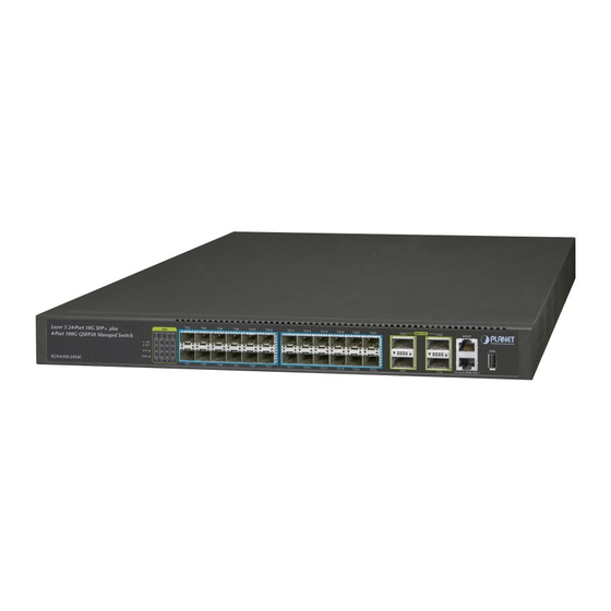
- Page 1 Layer 3 24-Port 10G SFP+ + 4-Port 100G QSFP28 Managed Switch XGS-6350-24X4C Quick Installation Guide...
-
Page 2: Table Of Contents
Table of Contents 1. Package Contents ..................3 2. Switch Management ..................4 3. Requirements ..................... 5 4. Terminal Setup ................... 6 4.1 Logging on to the Console..............7 4.2 Configuring IP Address ................. 8 4.3 Setting 1000BASE-X for 10G SFP+ Port ..........9 4.4 Setting 40GBASE-X for 100G SFP+ Port ..........10 4.5 Changing Password ................10 4.6 Saving the Configuration ..............11 5. -
Page 3: Package Contents
1. Package Contents Thank you for purchasing PLANET Layer 3 24-Port 10G SFP+ + 4-Port 100G QSFP28 Managed Switch, XGS-6350-24X4C. Unless specified, “Managed Switch” mentioned in this Quick Installation Guide refers to the XGS-6350-24X4C. Open the box of the Managed Switch and carefully unpack it. The box should... -
Page 4: Switch Management
2. Switch Management To set up the Managed Switch, the user needs to configure the Managed Switch for network management. The Managed Switch provides two management options: Out-of-Band Management and In-Band Management. Out-of-Band Management Out-of-band management is the management through console interface. Generally, the user will use out-of-band management for the initial switch configuration, or when in-band management is not available. -
Page 5: Requirements
3. Requirements z Workstations running Windows XP/2003/Vista/2008/7/8/10, MAC OS X or later, Linux, UNIX, or other platforms are compatible with TCP/IP protocols. z Workstations are installed with Ethernet NIC (Network Interface Card) z Serial Port Connection (Terminal) The above Workstations come with COM Port (DB9) or USB-to-RS232 converter. The above Workstations have been installed with terminal emulator, such as Tera Term or PuTTY. -
Page 6: Terminal Setup
4. Terminal Setup To configure the system, connect a serial cable to a COM port on a PC or notebook computer and to serial (console) port of the Managed Switch. The console port of the Managed Switch is DCE already, so that you can connect the console port directly through PC without the need of Null Modem. -
Page 7: Logging On To The Console
4.1 Logging on to the Console Once the terminal is connected to the device, power on the Managed Switch, and the terminal will display “running testing procedures”. Then, the following message asks for the login user name and password. The factory default user name and password are as follows as the login screen in Figure 4-3 appears. -
Page 8: Configuring Ip Address
4.2 Configuring IP Address The IP address configuration commands for VLAN1 interface are listed below. Before using in-band management, the Managed Switch must be configured with an IP address by out-of-band management (i.e. console mode). The configuration commands are as follows: Switch#config Switch_config#interface vlan 1 Switch_config_v1#ip address 192.168.1.254 255.255.255.0 The previous command would apply the following settings for the Managed Switch. -
Page 9: Setting 1000Base-X For 10G Sfp+ Port
If the IP is successfully configured, the Managed Switch will apply the new IP address setting immediately. You can access the Web interface of Managed Switch through the new IP address. If you are not familiar with console command or the related param- eter, enter “help” anytime in console to get the help description. Note 4.3 Setting 1000BASE-X for 10G SFP+ Port The Managed Switch supports both 1000BASE-X and 10GBASE-X SFP transceivers by manual setting and the default SFP+ port speed is set to 10Gbps. -
Page 10: Setting 40Gbase-X For 100G Sfp+ Port
4.4 Setting 40GBASE-X for 100G SFP+ Port The Managed Switch supports both 40GBASE-X and 100GBASE-X SFP transceivers by manual setting and the default SFP+ port speed is set to 100Gbps. For example, to establish the fiber connection with 40GBASE-X SFP transceiver in the cgigaethernet 0/1, the following command configuration is required: Switch#config Switch_config#interface cgigaethernet 0/1 Switch_config_cg0/1#speed 40000 Switch_config_cg0/1#exit Switch_config#interface range cgigaethernet 0/2-4 Switch_config_if_range#speed 40000 Switch_config_if_range# Figure 4-7 Setting 40GBASE-FX Screen 4.5 Changing Password... -
Page 11: Saving The Configuration
4.6 Saving the Configuration In Managed Switch, the running configuration file stores in the RAM. In the current version, the running configuration sequence running-config can be saved from the RAM to FLASH by write command, so that the running configuration sequence becomes the start-up configuration file, which is called configuration save. Switch#write Figure 4-9 Write Screen... -
Page 12: Starting Web Management
5. Starting Web Management The Managed Switch provides a built-in browser interface. You can manage it remotely by having a remote host with Web browser, such as Microsoft Internet Explorer, Mozilla Firefox, Google Chrome or Apple Safari. Managed Switch MGMT RJ45/UTP Cable IP Address: 192.168.1.1 PC/Workstation with Web Browser 192.168.1.x PC/Workstation with... -
Page 13: Logging In To The Managed Switch From Management Port
5.1 Logging in to the Managed Switch from Management Port 1. Use Internet Explorer 8.0 or above Web browser and enter IP address http://192.168.1.1 (that you have just set in console) to access the Web interface. 2. When the following dialog box appears, please enter the configured username “admin” and password “admin” (or the username/password you have changed via console). The login screen in Figure 5-2 appears. -
Page 14: Saving Configuration Via The Web
4. The Switch Menu on the left of the Web page lets you access all the commands and statistics the Switch provides. Now, you can use the Web management interface to continue the Switch management or manage the Managed Switch by console interface. Please refer to the user manual for more. -
Page 15: Led Indicators
6. LED Indicators System Color Function Green Lights to indicate that the Switch has power. Power is off. Blinks to indicate the system diagnosis is completed; Green lights to indicate the system is normally starting up. SFP+ Interfaces Color Function Blinks to indicate the data is transmitting and LNK/ACT Green receiving through the port; lights to indicate the link on the port is normal. -
Page 16: Customer Support
PLANET Web site first to check if it could solve your issue. If you need more support information, please contact PLANET switch support team. PLANET online FAQs: http://www.planet.com.tw/en/support/faq.php?type=1 Switch support team mail address: support_switch@planet.com.tw XGS-6350-24X4C User’s Manual http://www.planet.com.tw/en/support/download.php?view=3&key=XGS-6350-24X4C#list Copyright © PLANET Technology Corp. 2018. Contents are subject to revision without prior notice. PLANET is a registered trademark of PLANET Technology Corp. All other trademarks belong to their respective owners.
Need help?
Do you have a question about the XGS-6350-24X4C and is the answer not in the manual?
Questions and answers