
Related Manuals for Harmar Mobility VPL400-X


Summary of Contents for Harmar Mobility VPL400-X
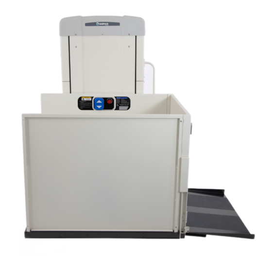
- Page 1 VPL400-X VERTICAL PLATFORM LIFT INSTALLATION & SERVICE MANUAL 21JULY2023 | 630-00159 B...
-
Page 3: Table Of Contents
Temporary Electrical Connection ......13 Environmental Conditions ........4 Bypass Mode ............14 INTRODUCTION ..................5 Platform Connection ........... 14 Device Name: Harmar VPL400-X ......5 Routing Interlock & Call/Send Wires Read And Understand ........... 5 Inside The Tower ..........15 Technical Specifications ........5 Installing Platform Guard Panels Straight Code Statement ............ -
Page 4: Safety
VPL400-X: SECTION 1 SAFETY SECTION 1 SAFETY SAFETY DEFINITIONS ENVIRONMENTAL CONDITIONS This safety alert symbol appears with safety statements. It means attention, The technician shall assess the surrounding become alert, your safety and the conditions and verify that the location is acceptable... -
Page 5: Introduction
SECTION 2 INTRODUCTION DEVICE NAME: HARMAR CODE STATEMENT VPL400-X The Harmar VPL400-X lift has been designed to meet Safety standard ASME A18.1-2020 “Safety Indications of Use: Standard for Platform Lifts and Stairway Chairlifts” The Harmar Highlander 400-X Vertical Platform under section 5 and has been certified to CSA B44.1/ Lift is to aid in the safe and efficient transfer of ASME A17.5-2019 “Elevator and Escalator Electrical... -
Page 6: Requirements Under Asme A18.1
ASME A18.1 Safety standard ASME A18.1-2020 for Platform Lifts and Stairway Chairlifts under Section 5. The Harmar VPL400-X Vertical Platform Lift is to be installed according to all applicable codes in accordance with Safety standard ASME A18.1-2020 - which is the responsibility of the installer - CSA B44.1/ASME A17.5-2019. -
Page 7: Key Vertical Platform Lift Elements
VPL400-X: SECTION 2 INTRODUCTION KEY VERTICAL PLATFORM LIFT ELEMENTS Top Cap Decal Data Serial Tag Platform Platform Guard Panel Grab Rail (if supplied) Platform Controls Platform Safety Pan Platform Folding Ramp/ Platform Fixed Ramp 10. Tower 11. Folding Ramp Actuator Tube... -
Page 8: Key Internal Vertical Platform Lift Elements
VPL400-X: SECTION 2 INTRODUCTION KEY INTERNAL VERTICAL PLATFORM LIFT ELEMENTS 1. Manual Lowering Tool 2. Motor / Gearbox 3. ACME Screw with Drive and Safety nuts 4. Control Electronics Assembly 5. Tower Frame 6. Tower Legs 7. Wire Channel 8. Over-Speed Safety Assembly 9. -
Page 9: Preparation
VPL400-X: SECTION 3 PREPARATION SECTION 3 PREPARATION Installations may vary to some degree, but below • Concrete Drill Bits are the basic tools to have on hand for a Vertical • Temporary Power Means Platform Lift installation. • Precision Screwdriver Set If you have any questions, concerns or comments, •... -
Page 10: Site Preparation
VPL400-X: SECTION 3 PREPARATION SITE PREPARATION CAUTION • Review and confirm the power requirements for power supply and disconnect per NFPA 70. Wood shims should never be used on either inside or outside applications. • In preparation for receiving the lift for installation a final site inspection must be NOTE: Do not shim more than 7/8". -
Page 11: Unloading
VPL400-X: SECTION 3 PREPARATION UNLOADING BOX CONTENT • The 4' VPL is shipped standing up shrink Inspect all of the boxes for damage or missing parts. wrapped to a pallet. The pallet dimensions If you see any damage, contact the freight carrier to are 48"... -
Page 12: Installation
VPL400-X: SECTION 4 INSTALLATION SECTION 4 INSTALLATION TOWER PREPARATION 4. Position the VPL tower close to the upper landing and stand it up using appropriate material handling processes. 1. Remove 5X front screws. NOTE: Tower frame should only be lifted by the 2. -
Page 13: Temporary Electrical Connection
VPL400-X: SECTION 4 INSTALLATION NOTE: Be sure that the pulley assembly is suspended with WARNING the sheeve at the top and that it is clear to move through the lift range. Verify that hot, neutral and ground conductors where the temporary power cord will connect are 6. -
Page 14: Bypass Mode
VPL400-X: SECTION 4 INSTALLATION BYPASS MODE 3. Move the carriage up or down as needed to finish the installation. To operate the carriage during installation, prior to 4. These jumpers may need to be removed at the completion of installation. See Installation gate and platform setup, several jumper plugs are required. -
Page 15: Routing Interlock & Call/Send Wires Inside The Tower
VPL400-X: SECTION 4 INSTALLATION ROUTING INTERLOCK & INSTALLING PLATFORM CALL/SEND WIRES INSIDE GUARD PANELS STRAIGHT THE TOWER THROUGH CONFIGURATION Depending on the configuration call/send and or 1. Remove the four (4) 1/4" - 20 x 4" bolts from interlock wires will be wired directly to the control the small parts bag. -
Page 16: Installing A Platform Gate (If Required)
VPL400-X: SECTION 4 INSTALLATION INSTALLING A PLATFORM GATE (IF REQUIRED) 1. Place the gate onto the platform floor and align the gate tabs with the threaded holes on the side panels. See Figure 4-18. Figure 4-16 4. Grab the top of the panel and push it back and forth to check the rigidity. - Page 17 VPL400-X: SECTION 4 INSTALLATION 3. Using a #1 Phillips screwdriver remove the 6. Continue routing through the bottom tube interlock covers screws. See Figure 4-20. and out the other end. Install the rectangular caps into the bottom gate tube. Create a small notch in the rectangular cap to route the harness through after it is installed.
-
Page 18: Installing The Auto-Folding Ramp
VPL400-X: SECTION 4 INSTALLATION INSTALLING THE 3. Remove the three (3) screws holding the tower skins to the tower and install the ramp actuator tube in AUTO-FOLDING RAMP the orientation shown below using the hardware that was previously removed. See Figure 4-26. -
Page 19: Fascia Panel Installation
VPL400-X: SECTION 4 INSTALLATION FASCIA PANEL INSTALLING THE TOP INSTALLATION LANDING GATE The fascia panel sections are available in 53" and NOTE: If the call/send switch is installed in the gate, the 24" heights and 43" and 49" widths. Custom fascia wires are routed between the gate and to the top of the panel heights can be special ordered. - Page 20 VPL400-X: SECTION 4 INSTALLATION 3. With the gate in the open position place, it in 5. Use the two (2) access holes on each side between the upright structural supports. of the gate to fasten it in place. Fasteners See Figure 4-30.
-
Page 21: Lower Landing Call Stations
VPL400-X: SECTION 3 PREPARATION 6. Run the wire through the wire routing slot and 3. If there is a lower landing call/send, replace to the interlock. See Figure 4-29 on page 19. the lower landing jumper connector with the lower landing cable and route the cable to the 7. -
Page 22: Interlocks
VPL400-X: SECTION 4 INSTALLATION INTERLOCKS SETTING THE LIMIT SWITCHES The approved interlocks (EMI) are Harmar and Honeywell. See wiring sections pages 29-31. The upper and lower limit switches are set from the factory will need to be adjusted based upon the INSTALLING FIXED RAMPS landing heights at the installation site. -
Page 23: Final Positioning And Anchoring
VPL400-X: SECTION 4 INSTALLATION FINAL POSITIONING AND INSTALLATION TOWER ANCHORING CHECKS 79" of overhead clearance is required above the Before reinstalling the top cap and front panels, platform floor when the lift is at the upper landing. an operational check should be completed on the internal tower safety features. -
Page 24: Permanent Power Installation
VPL400-X: SECTION 4 INSTALLATION PERMANENT POWER FINAL INSTALLATION INSTALLATION WARNING Permanent power can be installed at various points in the overall installation process; however, it must Jumpers MUST be removed at completion of be installed by a qualified electrical contractor in installation and confirm safety features are compliance with local codes and regulations. -
Page 25: Operational Check
VPL400-X: SECTION 4 INSTALLATION OPERATIONAL CHECK Upon installation and at scheduled intervals the operation of the VPL must be verified. Apply power. Paddle/buttons on cab controls control UP and DOWN travel. E-Stop PRESSED IN stops and prevents travel ... -
Page 26: Installation Quick Start
VPL400-X: SECTION 5 INSTALLATION QUICK START SECTION 5 INSTALLATION QUICK START ELECTRIC CONTROL Upon completion of the installation, it is imperative to review all contents of the Owner’s Manual with the customer and provide a thorough demonstration and familiarization of the lift. -
Page 27: Quick Start Checklist
VPL400-X: SECTION 5 INSTALLATION QUICK START QUICK START CHECKLIST SITE PREP Code Compliance Attach to Open Areas Under Gate Upper Landing Ensure Smooth, Flush Foundation Level No Gaps, Protrusions etc. Electrical TIP: Use flat screw heads to avoid protrusions. -
Page 28: Installation Tower Checks
VPL400-X: SECTION 5 INSTALLATION QUICK START INSTALLATION TOWER FINAL INSTALLATION CHECKS 1. Install the front panel between the platform and tower. Slots in the bottom of the front Before reinstalling the top cap and front panels, panel should rest on the pins in the tower. -
Page 29: Quick Start Wiring
VPL400-X: SECTION 6 QUICK START WIRING VPL400-X: Install Manual 21JULY2023 | 630-00159 B... -
Page 30: Platform Gate Wire Connections
VPL400-X: SECTION 6 QUICK START WIRING VPL400-X: Install Manual 21JULY2023 | 630-00159 B... -
Page 31: Lower Landing Wire Connection
VPL400-X: SECTION 6 QUICK START WIRING VPL400-X: Install Manual 21JULY2023 | 630-00159 B... -
Page 32: Troubleshooting
VPL400-X: SECTION 7 TROUBLESHOOTING SECTION 7 TROUBLESHOOTING A BRAKE RELEASE toggle switch is only used during emergency lowering of the platform or positioning the platform during installation when power is not applied to the unit. See Figure 7-1. Figure 7-1... -
Page 33: Contactor Tray
VPL400-X: SECTION 7 TROUBLESHOOTING CONTACTOR TRAY BRAKE RESISTOR The Contactor Tray contains all electrical wiring for The Brake resistor electronically slows the motor the contacts. See Figure 7-3. quickly via eddy current braking. When both contactors are OFF the resistor essentially shorts the motor leads which resists motor shaft rotation. -
Page 34: Emergency Lowering Procedure
VPL400-X: SECTION 7 TROUBLESHOOTING EMERGENCY LOWERING The wrench fits over the 1/4" hex shaft at the end of the drive motor. It is designed to be PROCEDURE rotated by hand — clockwise, which will turn the screw and lower the platform. - Page 35 VPL400-X: SECTION 7 TROUBLESHOOTING WARNING Wait for a Harmar dealer to service and inspect the lift prior to using it again. Return the Brake Release switch to the down position to re-engage the brake. If the platform gate doesn’t open, use the interlock key to open the gate from the outside.
-
Page 36: Maintenance & Inspection
VPL400-X: SECTION 8 MAINTENANCE SECTION 8 MAINTENANCE & INSPECTION Annual inspections are required to help prevent • Check your key locks and emergency unsafe conditions and operation. stop button for functionality. Ensure user understands overrides and understands how to manually open the gate in the event of an RESIDENTIAL APPLICATIONS emergency. - Page 37 NOTES VPL400-X: Install Manual 21JULY2023 | 630-00159 B...
- Page 38 NOTES VPL400-X: Install Manual 21JULY2023 | 630-00159 B...
- Page 39 NOTES VPL400-X: Install Manual 21JULY2023 | 630-00159 B...
- Page 40 1500 Independence Blvd. Suite 220 Sarasota, FL 34234 800-833-0478 www.harmar.com...
Need help?
Do you have a question about the VPL400-X and is the answer not in the manual?
Questions and answers