
Related Manuals for Harmar Mobility HIGHLANDER II


Summary of Contents for Harmar Mobility HIGHLANDER II
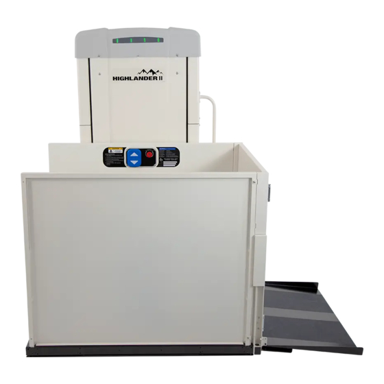
- Page 1 HIGHLANDER II VERTICAL PLATFORM LIFT INSTALLATION & SERVICE MANUAL 17FEB2021 | 630-00113 REV C...
-
Page 3: Table Of Contents
Battery Backup ..........13 INTRODUCTION ................5 Platform Connection ......... 14 Device Name: Harmar Highlander II VPL ....5 Installing the Platform Control Guard Panel ..14 Read and Understand .......... 5 Installing a Platform Gate (If Equipped) ..... 14 Technical Specifications ........ -
Page 4: Safety
NOTE: Indicates a condition that should be followed in order for the lift to function in the manner intended. Install Manual HIGHLANDER II VERTICAL PLATFORM LIFTS: 17FEB2021 | 630-00113 REV C... -
Page 5: Introduction
INTRODUCTION DEVICE NAME: HARMAR CODE STATEMENT HIGHLANDER II - The Harmar Highlander II lift has been designed to VERTICAL PLATFORM LIFT meet ASME A18.1 “Safety Standard for Platform Lifts and Stairway Chairlifts” under section 2 or section 5 and has been certified to CAN/CSA-B44.1/ Indications of Use: The Harmar Highlander II Vertical ASME A17.5 “Elevator and Escalator Electrical... -
Page 6: Requirements Under Asme A18.1
ASME A18.1 Safety Standards for Platform Lifts and Stairway Chairlifts under Section 2 or Section 5. The Harmar Highlander II Vertical Platform Lift is to be installed according to all applicable codes in accordance with ASME A18.1 - which is the responsibility of the installer - ASME A17.5 and CAN/... -
Page 7: Key Vertical Platform Lift Elements
Lift Status Indicator Lights Data Serial Tag Platform Platform Side Panel Grab Rail (if supplied) Platform Controls Platform Safety Pan Platform Folding Ramp/ Platform Fixed Ramp 10. Tower Install Manual HIGHLANDER II VERTICAL PLATFORM LIFTS: 17FEB2021 | 630-00113 REV C... -
Page 8: Key Internal Vertical Platform Lift Elements
10. Tower Legs 11. Wire Channel 12. Over-Speed Safety Assembly 13. Motor Contactors 14. Carriage 15. Trailing Cable 16. Cable Tensioning Pulley 17. Junction Box (Main Power Supply Hookup) Install Manual HIGHLANDER II VERTICAL PLATFORM LIFTS: 17FEB2021 | 630-00113 REV C... -
Page 9: Preparation
• 3/4" • Hard Hat • Allen Wrench: • 1/8" • Shop Vacuum • 3/16" • Shop Towels and General Purpose Cleaner • 5/16" • Torx Wrench • Install Manual HIGHLANDER II VERTICAL PLATFORM LIFTS: 17FEB2021 | 630-00113 REV C... -
Page 10: Box Content
• Platform This information must be documented on the evaluation • Gates form. 2. Remove the tower from the pallet. 3. Perform pre-delivery inspection Install Manual HIGHLANDER II VERTICAL PLATFORM LIFTS: 17FEB2021 | 630-00113 REV C... -
Page 11: Concrete
Care connection can be made. should be taken not to scratch or damage panels when removing, carrying, and reinstalling them. Install Manual HIGHLANDER II VERTICAL PLATFORM LIFTS: 17FEB2021 | 630-00113 REV C... -
Page 12: Installation
Incorrect wiring or lack of ground could NOTE: Tower frame should only be lifted by the cause unit malfunction. rectangular tubes below the top plate. Install Manual HIGHLANDER II VERTICAL PLATFORM LIFTS: 17FEB2021 | 630-00113 REV C... -
Page 13: Battery Backup
• Wrap 2X zip-ties around the outside of the lift and out to a temporary 120V AC perimeter of the batteries. outlet. See Figure 4-5. DO NOT OVERTIGHTEN. Install Manual HIGHLANDER II VERTICAL PLATFORM LIFTS: 17FEB2021 | 630-00113 REV C... -
Page 14: Platform Connection
4. Fasten the control box to the control guard panel securely with the four (4) screws and nuts. Connect the ground ring terminal to the bottom screw connecting the control box to the panel. Install Manual HIGHLANDER II VERTICAL PLATFORM LIFTS: 17FEB2021 | 630-00113 REV C... -
Page 15: Installing The Platform Front Guard Panel
3. Use shoulder bolts to attach the ramp to the pivot tabs. 4. To install the ramp roller guide, remove the inside top and bottom side panel screws. See Figure 4-8. Install Manual HIGHLANDER II VERTICAL PLATFORM LIFTS: 17FEB2021 | 630-00113 REV C... -
Page 16: Installing The Top Landing Gate
Sill mounting slots Figure 4-12 3. Remove small screws and post cover on the latch side of the landing gate with a No. 1 Phillips screwdriver. Figure 4-10 Install Manual HIGHLANDER II VERTICAL PLATFORM LIFTS: 17FEB2021 | 630-00113 REV C... -
Page 17: Fascia Panel Installation
Circuits will automatically reset when the wiring is corrected. 10. Reinstall interlock, gate post covers, and hole plugs. NOTE: Gates are field reversible (contact Harmar Technical Service for instructions). Install Manual HIGHLANDER II VERTICAL PLATFORM LIFTS: 17FEB2021 | 630-00113 REV C... -
Page 18: Setting The Upper Limit Switch
5. If using a flush-mounted setup the back cover can be discarded. 6. Mount back cover to the wall using appropriate fasteners through four (4) holes in the back surface of the back cover. Install Manual HIGHLANDER II VERTICAL PLATFORM LIFTS: 17FEB2021 | 630-00113 REV C... -
Page 19: Doors / Gates By Others
Install devices per instructions in the packaging. Connect wiring per device instructions and Figures 4-9 or Figure 4-11 on page 16. For details, please refer to the supplemental guide "Highlander II Wiring Schematics". NOTE: A wiring diagram with part number 640-00025 is Figure 4-16 placed in a packet with your shipment. -
Page 20: Installing Fixed Ramps
4-LED lights are solid red with no lift opening. movement. 2. Anchor the ramp to the concrete pad. Verify the screws securing the tower skins have a plastic washer and are tight. Install Manual HIGHLANDER II VERTICAL PLATFORM LIFTS: 17FEB2021 | 630-00113 REV C... -
Page 21: Final Installation
Indicator lights one (1) and (2) are flashing AMBER. Pit switch (if equipped) prevents UP and DOWN travel. Indicator lights 1, 2, and 3 are solid RED Install Manual HIGHLANDER II VERTICAL PLATFORM LIFTS: 17FEB2021 | 630-00113 REV C... -
Page 22: Permanent Power Installation
Be sure all wiring is routed clear of the moving carriage and roller wheels inside the tower. See Figure 4-19. Install Manual HIGHLANDER II VERTICAL PLATFORM LIFTS: 17FEB2021 | 630-00113 REV C... -
Page 23: Operator Familiarization
Call/Send Entrance and positioning Door/Gate interlocks and safety pan Status lights and color key Ascend/Descend Use of handrail (if equipped) Emergency lowering Install Manual HIGHLANDER II VERTICAL PLATFORM LIFTS: 17FEB2021 | 630-00113 REV C... -
Page 24: Installation Quick Start
Pre-run Wiring Insert permanent power installation Reattach Top Cap and Front Cover Operator Familiarization Complete Warranty Form Write Date/Info on Lift * If required/included Install Manual HIGHLANDER II VERTICAL PLATFORM LIFTS: 17FEB2021 | 630-00113 REV C... -
Page 25: Troubleshooting
Lift is on AC power and battery is Low. If lift transfers Amber Amber Amber to backup power it will only operate for at least one full lift cycle. Service or replace batteries. Install Manual HIGHLANDER II VERTICAL PLATFORM LIFTS: 17FEB2021 | 630-00113 REV C... - Page 26 *If battery is not replaced promptly after this warning, the battery will further degrade to the point that unit will shut off completely when AC power is lost. Install Manual HIGHLANDER II VERTICAL PLATFORM LIFTS: 17FEB2021 | 630-00113 REV C...
- Page 27 *If battery is not replaced promptly after this warning, the battery will further degrade to the point that unit will shut off completely when AC power is lost. Install Manual HIGHLANDER II VERTICAL PLATFORM LIFTS: 17FEB2021 | 630-00113 REV C...
-
Page 28: Control Electronics
The Control Electronics Tray contains the Control PCBA, power elements and fuses. See Figure 6-2. Bridge Power Transfer Transformer Motor Current Rectifier Relay Sensor AC In and Ground Screw Terminal 3A Circuit Breaker 15A Circuit Breaker Figure 6-2 Control Board Install Manual HIGHLANDER II VERTICAL PLATFORM LIFTS: 17FEB2021 | 630-00113 REV C... -
Page 29: Control Board
Connector Brake Connector Board Programming Connector Gate and Call (NOT USED) Down Contactor Up Contactor Trailing Cable Landing Switch Station Screw Connector Connector Connector Connectors Terminals Figure 6-3 Install Manual HIGHLANDER II VERTICAL PLATFORM LIFTS: 17FEB2021 | 630-00113 REV C... - Page 30 LED ON indicates processor is getting power. 24V Power Green LED ON indicates all 24V circuits are getting power. E-Stop Green LED ON indicates the E-stop is not depressed (lift can run) Install Manual HIGHLANDER II VERTICAL PLATFORM LIFTS: 17FEB2021 | 630-00113 REV C...
- Page 31 LED ON indicates the Down button in the Top Call Station is being Down Top Green depressed. Top Gate Green LED ON indicates the Top Gate/Door interlock is closed. Install Manual HIGHLANDER II VERTICAL PLATFORM LIFTS: 17FEB2021 | 630-00113 REV C...
- Page 32 Possible causes: Top Landing switch failure, connector open or wire break. LED ON indicates the Top Landing switch is closed. The switch should be Top Land Green closed only when platform is at that landing. Install Manual HIGHLANDER II VERTICAL PLATFORM LIFTS: 17FEB2021 | 630-00113 REV C...
- Page 33 “Out of Service Mode” flag is not cleared by pressing the RESET switch. WARNING Pressing and holding this switch could result in the platform slowly drifting down. Install Manual HIGHLANDER II VERTICAL PLATFORM LIFTS: 17FEB2021 | 630-00113 REV C...
-
Page 34: Gearmotor
Do not reset the "Out of Service Mode" flag until after temperatures fall below hot temperature required service has been performed. Unsafe thresholds. See STATUS CODES section for the codes operation could result. displayed. Install Manual HIGHLANDER II VERTICAL PLATFORM LIFTS: 17FEB2021 | 630-00113 REV C... -
Page 35: Contactor Tray
If the VPL is equipped with a Battery Backup System, it will be located inside the tower below the top plate. See Figure 6-7. Install Manual HIGHLANDER II VERTICAL PLATFORM LIFTS: 17FEB2021 | 630-00113 REV C... -
Page 36: Float Switch
"out of service" mode which will not allow it to run Between the positive leads of the batteries and (flashing #2 red). This is to protect the safety of the Install Manual HIGHLANDER II VERTICAL PLATFORM LIFTS: 17FEB2021 | 630-00113 REV C... -
Page 37: Emergency Evacuation Procedure
Lowering Procedure to evacuate the occupant. 5X front screws Remove the two wingnuts holding down the manual lowering tools (1/4" wrench and 1/4" x 3/8" drive socket). See Figure 6-9. EMERGENCY LOWERING Install Manual HIGHLANDER II VERTICAL PLATFORM LIFTS: 17FEB2021 | 630-00113 REV C... - Page 38 - rotating clockwise to WARNING lower the platform. See Figure 6-11. Wait for a Harmar dealer to service and inspect the lift prior to using it again. Install Manual HIGHLANDER II VERTICAL PLATFORM LIFTS: 17FEB2021 | 630-00113 REV C...
-
Page 39: Maintenance & Inspection
If for any reason the safety pan does condition and that there are no cracks or gaps not move as intended, please contact your dealer. in conduit. Install Manual HIGHLANDER II VERTICAL PLATFORM LIFTS: 17FEB2021 | 630-00113 REV C... -
Page 40: Maintenance Schedule
Check for any rust that may be developing. • Replace batteries (if equipped) Rust is expected in outdoor applications (especially in coastal areas), but with proactive maintenance or quick repair, this can be minimized. Install Manual HIGHLANDER II VERTICAL PLATFORM LIFTS: 17FEB2021 | 630-00113 REV C... - Page 41 HIGHLANDER II NOTES Install Manual HIGHLANDER II VERTICAL PLATFORM LIFTS: 17FEB2021 | 630-00113 REV C...
- Page 42 HIGHLANDER II NOTES Install Manual HIGHLANDER II VERTICAL PLATFORM LIFTS: 17FEB2021 | 630-00113 REV C...
- Page 43 HIGHLANDER II NOTES Install Manual HIGHLANDER II VERTICAL PLATFORM LIFTS: 17FEB2021 | 630-00113 REV C...
- Page 44 2075 47 Street | Sarasota, FL 34234 800.833.0478 harmar.com...
Need help?
Do you have a question about the HIGHLANDER II and is the answer not in the manual?
Questions and answers
Our "gate" locks almost every time! We have to use the long key. Very hard to use while you are in the lift trying to get out. Photo won't load!
@Dianne C. Harrison The photo did load. I hope someone has a suggestion. Each time our installer comes it seems to work. We live 30 miles from his office.
If the gate on the Harmar Mobility Highlander II lift locks frequently and is difficult to unlock, service may be required to inspect and repair the gate lock mechanism.
This answer is automatically generated
the lights are all green but when i push the button to operate they turn red and it doesnt move.
If the lights on the Harmar Mobility HIGHLANDER II are green but turn red when a button is pushed and the unit does not move, it likely indicates a fault condition or a safety circuit preventing operation. Possible causes include ACME nut failure, switch failure, an open connector, or a wire break. Additionally, check if any required interlocks or locks (such as gate/door interlocks) are not properly engaged, as these must be closed for normal operation.
This answer is automatically generated
Highlander ll the green indicators lights are off the doors won’t open but the emergency button still works if pull it will go on
my highlander does not go to battery power when unplugged