Table of Contents
Advertisement
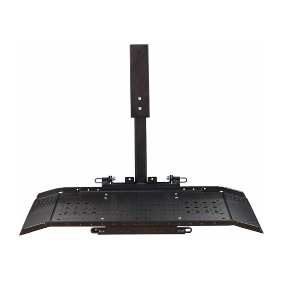
AL625
INSTALLATION & OWNER'S MANUAL
These instructions are provided to assist you in the installation of the AL625. If you require
further assistance, our trained staff is ready to provide you with quick, efficient service. Call our
toll-free number:
866.378.6648
Monday thru Friday, 8:00 AM – 8:00 PM (Except holidays) E.S.T
Before calling please have your serial number available.
2012 Harmar
AL625
Page 1
REV: 1-24-12
Advertisement
Table of Contents

Related Manuals for Harmar Mobility AL625


Summary of Contents for Harmar Mobility AL625
- Page 1 AL625 INSTALLATION & OWNER’S MANUAL These instructions are provided to assist you in the installation of the AL625. If you require further assistance, our trained staff is ready to provide you with quick, efficient service. Call our toll-free number: 866.378.6648 Monday thru Friday, 8:00 AM –...
-
Page 2: Table Of Contents
FUSE FOR RF REMOTE CONTROL CIRCUIT ………………………..………………………………………… 20 TRAINING THE END-USER ……………………………………………………………………………………… 20 MAINTAINING THE LIFT ……………………………………………………………………………………….. 20 TROUBLESHOOTING ……………………………………………………………………………………………. 21 ELECTRONIC CONTROL BOX WIRING DIAGRAM ...…………………………..……………………………. 22 FOR YOUR RECORDS SALESPERSON______________________________________ TELEPHONE________________________________________ PURCHASE DATE_________________________________LIFT SERIAL #______________________________________ CUSTOMER #_____________________________________ORDER #___________________________________________ AL625 Page 2 REV: 1-24-12... -
Page 3: Requirements And Considerations Before Installation
Before beginning installation, open the boxes and check that the contents match those on the packing list. ITEM DESCRIPTION TROLLEY ASSEMBLY PLATFORM ASSEMBLY INTERLOCK INSTALL KIT (not shown) CONTROL PENDANT (not shown) HARDWARE KIT (not shown) REMOTE CONTROL (not shown) BATERY CHARGER (not shown) MOUNTING BARS (not shown) AL625 Page 3 REV: 1-24-12... -
Page 4: Safety First
___ELECTRICAL TAPE ___ASSORTED WRENCHES AND SOCKETS (7/16”, 9/16” and 3/4" are important) ___ 5/32”, 3/16, 1/4”, and 5/16” ALLEN WRENCHES ___STANDARD SCREWDRIVER ___PHILLIPS HEAD SCREWDRIVERS, #1 & #2 ___PORTABLE VACUUM ___SILICON CAULK (RTV) ___ TAPE MEASURE AL625 Page 4 REV: 1-24-12... -
Page 5: Step 1
STEP 1 WIRING THE LIFT AL625 Page 5 REV: 1-24-12... -
Page 6: Step 2 Installing The Mounting Bars
Center the threaded holes in the MOUNTING BARS with the sides of the cargo area to center the lift. Example: Mounting Bars Installed AL625 Page 6 REV: 1-24-12... - Page 7 NOTE: IF YOU ARE INSTALLING THE TRACKER INTO A DODGE GRAND CARAVAN (OR SIMILAR CHRYSLER VAN), READ THE INSTRUCTIONS PAGE 13 ABOUT POSITIONING THE TRACKER TO LEAVE THE SPARE TIRE RELEASE BOLT ACCESSIBLE. AL625 Page 7 REV: 1-24-12...
-
Page 8: Mounting The Tracker Directly To The Vehicle's Floor
DAMAGE TO THE LIFT OR VEHICLE’S FLOOR. THIS CONDITION MAY CAUSE THE UNIT TO FAIL UNDER LOAD, THUS RISKING PERSONAL INJURY TO THE OPERATOR AND DAMAGE TO THE POWER CHAIR/SCOOTER AND/OR TO THE VEHICLE. STEP 3 AL625 Page 8 REV: 1-24-12... -
Page 9: Step 3 Position The Trolley Assembly On The Mounting Bars
POSITION THE TROLLEY ASSEMBLY ON THE MOUNTING BARS Place the trolley assembly into the vehicle, laying it on top of the mounting bars. Arrange the trolley assembly so it is facing as shown in the figure below. STEP 4 AL625 Page 9 REV: 1-24-12... -
Page 10: Step 4 Attach Leveling Feet To The Trolley Assembly
Trolley Assembly is evenly distributed on both of the mounting bars and leveling feet. Next- set the final position of the Trolley Assembly in the cargo area and tighten down all of the nuts and bolts. STEP 5 AL625 Page 10 REV: 1-24-12... -
Page 11: Step 5 Position The Trolley Assembly And Bolt It Down
Do one final check of the side-to-side alignment and distance to the threshold/sill, adjusting if needed, and then tighten down all of the hex nuts on the U-bolts, and the 3/8 bolts on the mounting bars. AL625 Page 11 REV: 1-24-12... -
Page 12: Step 6
Now, using the pendant to control the lift, press “IN” to extend the actuator. CAUTION: As you are raising the lift, watch the boom head to make certain it will not contact the roof of the cargo area. AL625 Page 12 REV: 1-24-12... - Page 13 Move unit out approximately 2” & remove (2) wood blocks located in tracks used to prevent shipping damage. Next you will determine if you should remove the High Threshold Kit that comes with your Trolley Assembly. AL625 Page 13 REV: 1-24-12...
-
Page 14: Step 7 Mounting The Platform Assembly To The Trolley Assembly
2 lower holes on the Vertical Tube. Insert the 3/8-16 Hex Head Cap Screws (Bolts) and washers; tighten the 3/8-16 nyloc nuts to hold the tube in place. AL625 Page 14 REV: 1-24-12... -
Page 15: Step 8 Check Clearances Without Load
Operate the Tracker without a load and check the clearance of the platform over the bumper and threshold of the vehicle. Check the side-to-side clearances. To adjust the side-to-side distance, loosen the 3/8 nuts on the U-bolts and slide the trolley assembly & mounting bars to one side or the other. AL625 Page 15 REV: 1-24-12... -
Page 16: Adjust Platform Angle To Suit Load (If Necessary)
ADJUST PLATFORM ANGLE TO SUIT LOAD – Power Chair or Scooter You will need a ¼” socket wrench to adjust the set screws. Adjust the platform so that it is level while the customer’s power chair/scooter is on it. AL625 Page 16 REV: 1-24-12... - Page 17 350 pounds. To adjust, loosen the jam nut on the screw, and turn the contact screw inward to increase the upward lift, OR outward to reduce the upward lift. AL625 Page 17 REV: 1-24-12...
-
Page 18: Step 11 Confirming Home Position And Locking Pin Alignment
(power chair/scooter) on. WARNING: THE ALIGNMENT PINS SECURE THE PLATFORM, AND TOGETHER WITH THE STRAPS, SECURE THE POWER CHAIR/SCOOTER TO THE TROLLEY ASSEMBLY DURING TRANSPORT. AN UNSECURED POWER CHAIR/SCOOTER CAN CAUSE SERIOUS INJURIES. AL625 Page 18 REV: 1-24-12... - Page 19 Installing Straps in the Center Positions Installing the side near the trolley assembly. Use 5/16 – 18 x 1” Button Head Socket Screw, 5/16 – 18 nylon insert lock nut, and one 5/16 SAE flat washers. AL625 Page 19 REV: 1-24-12...
- Page 20 3/8 x 1.25 fender washers, and a 3/8 – 16 nylon insert lock nut to secure the metal plate of the latch plate to the loop as shown below: The fender washers must contact the loop. AL625 Page 20...
-
Page 21: Fuse For Rf Remote Control Circuit
MONTHLY: Check all mounting hardware for tightness and signs of wear due to vehicle aging, rust, etc. TWICE A YEAR: Lubricate the lead screw with a small amount of wheel bearing grease. Lubricate all bearing points and moving parts using wheel-bearing grease. AL625 Page 21 REV: 1-24-12... -
Page 22: Troubleshooting
Adjust the contact screw on “boom mounted limit switch” Misalignment of lift, Alignment hardware not tightened. Inspect and adjust the lift alignment. platform not clearing Improper alignment during bumper, rubbing into installation. vehicle AL625 Page 22 REV: 1-24-12... -
Page 23: Electronic Control Box Wiring Diagram
ELECTRONIC CONTROL BOX WIRING DIAGRAM AL625 Page 23 REV: 1-24-12... - Page 24 AL625 Page 24 REV: 1-24-12...
- Page 25 AL625 Page 25 REV: 1-24-12...
Need help?
Do you have a question about the AL625 and is the answer not in the manual?
Questions and answers