
Related Manuals for WAGO 751-5702


Summary of Contents for WAGO 751-5702
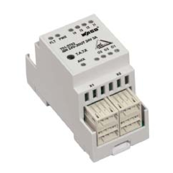
- Page 1 AS-Interface Components IP20 AS-Interface Module 4IN/3OUT 24V/2A A/B 751-5702 Manual Version 1.1.0...
- Page 2 • General Copyright © 2007 by WAGO Kontakttechnik GmbH & Co. KG All rights reserved. WAGO Kontakttechnik GmbH & Co. KG Hansastraße 27 D-32423 Minden Phone: +49 (0) 571/8 87 – 0 Fax: +49 (0) 571/8 87 – 1 69 E-Mail: info@wago.com...
-
Page 3: Table Of Contents
Number Notation ..................6 Safety Notes ..................... 7 Scope ......................7 2 AS-Interface Components ................8 AS-Interface Module IP20 ............... 8 2.1.1 751-5702 [AS-Interface Module 4IN/3OUT 24V/2A A/B] ....8 2.1.1.1 View....................8 2.1.1.2 Description..................8 2.1.1.3 Connectors ..................9 2.1.1.4... - Page 4 Fig. 2.1.1-10: Derating Output Current ..........16 gqxxx13d List of Tables Tab. 2.1.1-1: AS-Interface and AUX Connectors ..........9 Tab. 2.1.1-2: Sensor and Actuator Connectors..........10 Tab. 2.1.1-3: Display Elements ............... 11 Tab. 2.1.1-4: Technical Data ................13 WAGO-I/O-SYSTEM 751 AS-Interface Components IP20...
-
Page 5: Important Comments
WAGO Kontakttechnik GmbH & Co. KG declines all liability resulting from improper action and damage to WAGO products and third party products due to non-observance of the information contained in this manual. -
Page 6: Symbols
More information References on additional literature, manuals, data sheets and INTERNET pages 1.3 Number Notation Number Code Example Note Decimal normal notation Hexadecimal 0x64 C notation Binary '100' Within ', '0110.0100' Nibble separated with dots WAGO-I/O-SYSTEM 751 AS-Interface Components IP20... -
Page 7: Safety Notes
Do not use any contact spray. The spray may impair the functioning of the contact area. The AS-Interface Slaves IP20 from the WAGO-I/O-SYSTEM 751 are open components. They must only be assembled in housings, cabinets or in electrical operation rooms. Access must only be given via a key or tool to authorized qualified personnel. -
Page 8: As-Interface Components
The AS-Interface module 751-5202 provides 4 digital 24 V inputs and 3 digital 24 V / 2 A outputs. Sensors, actuators, AS-Interface power supply and actuator supply are connected using connectors from the WAGO Multi Connection System Mini. WAGO-I/O-SYSTEM 751 AS-Interface Components IP20... -
Page 9: Connectors
Sensor connections are 3-pole male connectors, actuator connections are 4- pole male connectors, both for use with female connectors from the Multi Connection System Mini. The following table shows the pin assignment of the sockets. WAGO-I/O-SYSTEM 751 AS-Interface Components IP20... -
Page 10: Tab. 2.1.1-2: Sensor And Actuator Connectors
On the left side of the front plate is the programming connector. It is a plug for a DC socket, which is compatible with all popular programming adapters, for example Pepperl+ Fuchs VAZ-PK-1.5M-V1-G. Please note manufacturer documentation for the operation of the programming device. WAGO-I/O-SYSTEM 751 AS-Interface Components IP20... -
Page 11: Display Elements
(Open-Load-Detection) AS-Interface supply error AS-Interface green supply AS-Interface supply OK Actuator supply error Actuator green supply Actuator supply OK 2.1.1.5 Operating Elements The AS-Interface module 751-5702 has no operating elements. WAGO-I/O-SYSTEM 751 AS-Interface Components IP20... -
Page 12: Schematic View
OUT1 OUT3 OUT1 OUT3 OUT1/3 Load OUT - OUT - AUX+ AUX+ AUX + AUX - AUX- AUX- AUX - AUX + OUT2 OUT2 OUT2 OUT - AUX - 751-5702 Fig. 2.1.1-6: Schematic View gq57021e WAGO-I/O-SYSTEM 751 AS-Interface Components IP20... -
Page 13: Technical Data
+ active 7 mA current sink (type 2) Signal voltage (0) ≤ 5 V Signal voltage (1) ≥ 11 V Connection system Multi Connection System Mini headers, WAGO series 734, 3-pole Outputs Number of outputs Output types Electronic outputs PNP Isolation ASI / AUX Temporary overload acc. - Page 14 I-2 / O-2 bidirectional I-3 / O-3 bidirectional I-4 / O-4 Connection system Multi Connection System Mini headers, WAGO series 734, 4-pole General Technical Data Operating temperature -25 °C ... +70 °C Storage temperature -25 °C ... +85 °C...
-
Page 15: Fig. 2.1.1-7: Characteristic Input Curve
1 – 16, 40x Marker strips, self-adhesive 709-180 height of marker strips 3 mm, printing 17 – 32, 40x Characteristic Input Curve Input Voltage Input Voltage Fig. 2.1.1-7: Characteristic Input Curve gqxxx15e Dimensions 42.5 Fig. 2.1.1-8: Dimensions gqxxx11x WAGO-I/O-SYSTEM 751 AS-Interface Components IP20... -
Page 16: Fig. 2.1.1-9: Derating Sensor Supply
The derating curves are based on the vertical mounting position of the modules on a DIN rail. Example: A total sensor supply current of 100 mA is permitted at an environmental temperature of 55 °C with a total output current of 6 A. WAGO-I/O-SYSTEM 751 AS-Interface Components IP20... -
Page 17: Assembly
The IP20 AS-Interface Slaves must only be used in enclosures, cabinets or electrical service rooms. Only authorized qualified personnel are allowed to access via key or tool. Depending on the type of slave, 3- or 4-pole WAGO female connectors of ® Series 734 (CAGE CLAMP connection) for the connection of AS-Interface, AUX, sensors or actuators are included in the delivery. - Page 18 WAGO Kontakttechnik GmbH & Co. KG Postfach 2880 • D-32385 Minden Hansastraße 27 • D-32423 Minden Phone: 05 71/8 87 – 0 Fax: 05 71/8 87 – 1 69 E-Mail: info@wago.com Internet: http://www.wago.com...
Need help?
Do you have a question about the 751-5702 and is the answer not in the manual?
Questions and answers