
Related Manuals for WAGO I/O-SYSTEM 751-3002


Summary of Contents for WAGO I/O-SYSTEM 751-3002
- Page 1 AS-Interface Components IP67 AS-Interface Module 4IN 24V A/B 751-3002 Manual Version 1.1.0...
- Page 2 • General Copyright © 2007 by WAGO Kontakttechnik GmbH & Co. KG All rights reserved. WAGO Kontakttechnik GmbH & Co. KG Hansastraße 27 D-32423 Minden Phone: +49 (0) 571/8 87 – 0 Fax: +49 (0) 571/8 87 – 1 69 E-Mail: info@wago.com...
-
Page 3: Table Of Contents
View....................8 2.1.1.2 Description..................8 2.1.1.3 Connectors ..................9 2.1.1.4 Display Elements ................10 2.1.1.5 Operating Elements............... 10 2.1.1.6 Schematic Diagram............... 11 2.1.1.7 Technical Data ................12 2.1.1.8 Assembly..................15 2.1.1.9 Start-up and diagnosis..............16 WAGO-I/O-SYSTEM 751 AS-Interface Components IP67... - Page 4 ..........14 gqxxx15e Fig. 2.1.1-6: Dimensions ..............14 gqxxx08x Fig. 2.1.1-7: Assembly ................. 15 gqxxx10x List of Tables Tab. 2.1.1-1: Sensor Connectors................ 9 Tab. 2.1.1-2: Display Elements ............... 10 Tab. 2.1.1-3: Technical Data ................12 WAGO-I/O-SYSTEM 751 AS-Interface Components IP67...
-
Page 5: Important Comments
WAGO Kontakttechnik GmbH & Co. KG declines all liability resulting from improper action and damage to WAGO products and third party products due to non-observance of the information contained in this manual. -
Page 6: Symbols
More information References on additional literature, manuals, data sheets and INTERNET pages 1.3 Number Notation Number Code Example Note Decimal normal notation Hexadecimal 0x64 C notation Binary '100' Within ', '0110.0100' Nibble separated with dots WAGO-I/O-SYSTEM 751 AS-Interface Components IP67... -
Page 7: Safety Notes
IP67 degree of protection! 1.5 Scope This manual describes the Digital Input Module 751-3002 AS-Interface Module 4IN 24V A/B of the modular WAGO-I/O-SYSTEM 751. Handling, assembly and start-up are described in the manual of the Fieldbus Coupler. Therefore this documentation is valid only in the connection with the appropriate manual. -
Page 8: As-Interface Components
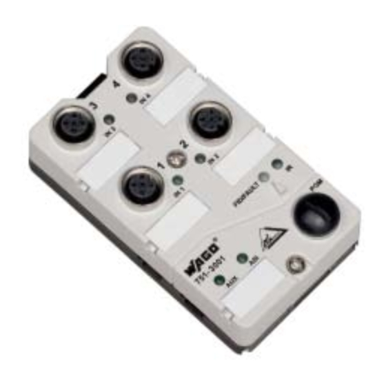
The AS-Interface module 751-3002 provides 4 digital 24 V inputs. The sensors are connected using M12x1 round plugs. The AS-Interface cable can be connected directly. LEDs indicate the status of inputs, the AS-Interface supply as well as a short circuit or overload condition. WAGO-I/O-SYSTEM 751 AS-Interface Components IP67... -
Page 9: Connectors
The IN 2 or IN 4 socket will then remain unconnected. Warning The inputs are DC coupled with the AS-Interface voltage. They shall not be supplied with an external supply voltage! Warning Unused sensor connections must be sealed with protective caps! WAGO-I/O-SYSTEM 751 AS-Interface Components IP67... -
Page 10: Display Elements
AS-Interface supply OK 2.1.1.5 Operating Elements Above the programming connector is an infrared sensor for communication with a programming device with optical interface. Please note manufacturer documentation for the operation of the programming device. WAGO-I/O-SYSTEM 751 AS-Interface Components IP67... -
Page 11: Schematic Diagram
• 11 Schematic Diagram 2.1.1.6 Schematic Diagram Sensor + IN1/3 Sensor IN - IN - for 3-conductor sensors FID/FAULT IN2/4 IN - IN - AS-i - NTERFACE AS-i + 751-3002 Fig. 2.1.1-4: Schematic Diagram gq30021e WAGO-I/O-SYSTEM 751 AS-Interface Components IP67... -
Page 12: Technical Data
62 (1A ... 31A, 1B ... 31B) ID-code 0.A.7.2 Operation indicators (LED) Input / Output function yellow Error Function (ASI) green Assignment of data bits bidirectional I-1 bidirectional I-2 bidirectional I-3 bidirectional I-4 Connection system AS-Interface cable (contacted via piercing technology) WAGO-I/O-SYSTEM 751 AS-Interface Components IP67... - Page 13 M12 plug, straight, 5-pole, screw clamp 756-9201/050-000 connection M12 plug, right angle, 5-pole, screw clamp 756-9204/050-000 connection Fitted cables (series 756) see catalog or www.wago.com M12 protective cap 755-814 Marker card (40 tags / card) 755-891 Felt-tip pen, for permanent marking 210-110...
-
Page 14: Fig. 2.1.1-5: Characteristic Input Curve
14 • 751-3002 [AS-Interface Module 4IN 24V A/B] Technical Data Tab. 2.1.1-3: Technical Data Characteristic Input Curve Input Voltage Input Voltage Fig. 2.1.1-5: Characteristic Input Curve gqxxx15e Dimensions Fig. 2.1.1-6: Dimensions gqxxx08x WAGO-I/O-SYSTEM 751 AS-Interface Components IP67... -
Page 15: Assembly
3. Fix the upper part in the snap-in position in the ground plate. 4. Push the upper part onto the ground plate. Tighten screws in the upper part with a tightening torque of 0.9 Nm. Electrical contact with the conductors is made automatically. Fig. 2.1.1-7: Assembly gqxxx10x WAGO-I/O-SYSTEM 751 AS-Interface Components IP67... -
Page 16: Start-Up And Diagnosis
AS-Interface specification may lead to malfunctions or restrictions. Please note the AS interface master manual and the manual for the start-up tool WAGO-I/O-CHECK 2 (759-302) for start-up and diagnosis of the AS interface slaves with AS interface master 750-655 from the WAGO-I/O- SYSTEM 750. - Page 17 751-3002 [AS-Interface Module 4IN 24V A/B] • 17 Start-up and diagnosis WAGO-I/O-SYSTEM 751 AS-Interface Components IP67...
- Page 18 WAGO Kontakttechnik GmbH & Co. KG Postfach 2880 • D-32385 Minden Hansastraße 27 • D-32423 Minden Phone: 05 71/8 87 – 0 Fax: 05 71/8 87 – 1 69 E-Mail: info@wago.com Internet: http://www.wago.com...
Need help?
Do you have a question about the I/O-SYSTEM 751-3002 and is the answer not in the manual?
Questions and answers