
Related Manuals for WAGO 751-5201


Summary of Contents for WAGO 751-5201
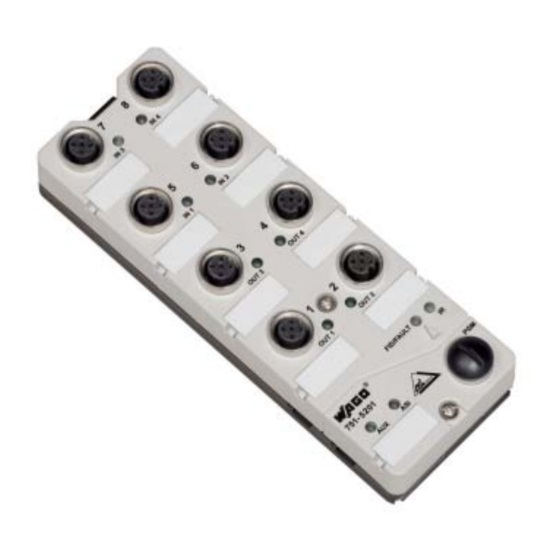
- Page 1 AS-Interface Components IP67 AS-Interface Module 4IN/4OUT 24V/2A Single 751-5201 Manual Version 1.1.0...
- Page 2 • General Copyright © 2007 by WAGO Kontakttechnik GmbH & Co. KG All rights reserved. WAGO Kontakttechnik GmbH & Co. KG Hansastraße 27 D-32423 Minden Phone: +49 (0) 571/8 87 – 0 Fax: +49 (0) 571/8 87 – 1 69 E-Mail: info@wago.com...
-
Page 3: Table Of Contents
Number Notation ..................6 Safety Notes ..................... 7 Scope ......................7 2 AS-Interface Components ................8 AS-Interface Module IP67 ............... 8 2.1.1 751-5201 [AS-Interface Module 4IN/4OUT 24V/2A Single] .... 8 2.1.1.1 View....................8 2.1.1.2 Description..................8 2.1.1.3 Connectors ..................9 2.1.1.4... - Page 4 Fig. 2.1.1-7: Dimensions ..............16 gqxxx09x Fig. 2.1.1-8: Assembly ................. 17 gqxxx10x List of Tables Tab. 2.1.1-1: Sensor and Actuator Connectors..........9 Tab. 2.1.1-2: Display Elements ............... 11 Tab. 2.1.1-3: Technical Data ................13 WAGO-I/O-SYSTEM 751 AS-Interface Components IP67...
-
Page 5: Important Comments
WAGO Kontakttechnik GmbH & Co. KG declines all liability resulting from improper action and damage to WAGO products and third party products due to non-observance of the information contained in this manual. -
Page 6: Symbols
More information References on additional literature, manuals, data sheets and INTERNET pages 1.3 Number Notation Number Code Example Note Decimal normal notation Hexadecimal 0x64 C notation Binary '100' Within ', '0110.0100' Nibble separated with dots WAGO-I/O-SYSTEM 751 AS-Interface Components IP67... -
Page 7: Safety Notes
Unused connection sockets must be sealed with filler plugs in order to keep IP67 degree of protection! 1.5 Scope This manual describes the Digital Input Module 751-5201 AS-Interface Module 4IN/4OUT 24V/2A Single of the modular WAGO-I/O- SYSTEM 751. Handling, assembly and start-up are described in the manual of the Fieldbus Coupler. -
Page 8: As-Interface Components
The voltage for the actuators is supplied via the AUX black cable. The AS-Interface module 751-5201 provides 4 digital 24 V inputs and 4 digital 24 V / 2 A outputs. The sensors and actuators are connected using M12x1 round plugs. The AS- Interface cable and the AUX cable can be connected directly. -
Page 9: Connectors
751-5201 [AS-Interface Module 4IN/4OUT 24V/2A Single] • 9 Connectors 2.1.1.3 Connectors 2.1.1.3.1 AS-Interface Cable and AUX Cable The AS Interface cable and the AUX cable are connected using piercing technology. When assembling the upper part, contacts are pressed into the cable which is located in the ground plate, making the electrical contact. - Page 10 10 • 751-5201 [AS-Interface Module 4IN/4OUT 24V/2A Single] Connectors Warning The inputs are DC coupled with the AS-Interface voltage. They shall not be supplied with an external supply voltage! Warning Unused sensor or actuator connections must be sealed with protective caps! 2.1.1.3.3 Programming Connector...
-
Page 11: Display Elements
751-5201 [AS-Interface Module 4IN/4OUT 24V/2A Single] • 11 Display Elements 2.1.1.4 Display Elements Tab. 2.1.1-2: Display Elements Designation Status Function Input 1, Signal voltage (0) IN 1 Status yellow Input 1, Signal voltage (1) Input 2, Signal voltage (0) IN 2... -
Page 12: Schematic Diagram
12 • 751-5201 [AS-Interface Module 4IN/4OUT 24V/2A Single] Schematic Diagram 2.1.1.6 Schematic Diagram Sensor + IN1/3 Sensor IN - IN - for 3-conductor sensors FID/FAULT IN2/4 IN - IN - AS-i - AUX + OUT1 OUT3 NTERFACE AS-i + OUT1... -
Page 13: Technical Data
751-5201 [AS-Interface Module 4IN/4OUT 24V/2A Single] • 13 Technical Data 2.1.1.7 Technical Data Tab. 2.1.1-3: Technical Data Inputs Number of inputs Sensor supply via AS-Interface control 200 mA, short-circuit-proof voltage max. Current limitation for all inputs 200 mA tot. Rated voltage 18 V ... - Page 14 14 • 751-5201 [AS-Interface Module 4IN/4OUT 24V/2A Single] Technical Data Tab. 2.1.1-3: Technical Data AS-Interface Operating voltage (AS-I) 26,5 V ... 31,6 V Current consumption 35 mA type Current consumption 50 mA (start-up), max. 280 mA incl. sensor supply AS-Interface version AS-Interface profile S-7.F.E...
-
Page 15: Fig. 2.1.1-6: Characteristic Input Curve
751-5201 [AS-Interface Module 4IN/4OUT 24V/2A Single] • 15 Technical Data Tab. 2.1.1-3: Technical Data Accessories M12 plug, straight, 4-pole, screw clamp 756-9201/040-000 connection M12 plug, right angle, 4-pole, screw clamp 756-9204/040-000 connection M12 plug, straight, 5-pole, screw clamp 756-9201/050-000 connection... -
Page 16: Fig. 2.1.1-7: Dimensions
16 • 751-5201 [AS-Interface Module 4IN/4OUT 24V/2A Single] Technical Data Tab. 2.1.1-3: Technical Data Dimensions Fig. 2.1.1-7: Dimensions gqxxx09x WAGO-I/O-SYSTEM 751 AS-Interface Components IP67... -
Page 17: Assembly
751-5201 [AS-Interface Module 4IN/4OUT 24V/2A Single] • 17 Assembly 2.1.1.8 Assembly 1. Mount ground plate on an even surface (machine frame or mounting plate) using sufficiently long M4 cheese-head screws 2. Place the cables in the cutouts that are marked for this purpose. Make sure that the cables engage behind the locking latch. -
Page 18: Start-Up And Diagnosis
AS-Interface specification may lead to malfunctions or restrictions. Please note the AS interface master manual and the manual for the start-up tool WAGO-I/O-CHECK 2 (759-302) for start-up and diagnosis of the AS interface slaves with AS interface master 750-655 from the WAGO-I/O- SYSTEM 750. - Page 19 751-5201 [AS-Interface Module 4IN/4OUT 24V/2A Single] • 19 Start-up and diagnosis WAGO-I/O-SYSTEM 751 AS-Interface Components IP67...
- Page 20 WAGO Kontakttechnik GmbH & Co. KG Postfach 2880 • D-32385 Minden Hansastraße 27 • D-32423 Minden Phone: 05 71/8 87 – 0 Fax: 05 71/8 87 – 1 69 E-Mail: info@wago.com Internet: http://www.wago.com...
Need help?
Do you have a question about the 751-5201 and is the answer not in the manual?
Questions and answers