Advertisement
Quick Links
Advertisement

Subscribe to Our Youtube Channel
Related Manuals for TMG TMG-DT4041CG


Summary of Contents for TMG TMG-DT4041CG
- Page 1 www.tmgindustrial.com 0/32 TOLL FREE:1-877-761-2819...
-
Page 2: Main Specifications
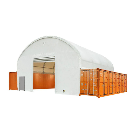
DT4041C DUAL TRUSS CONTAINER SHELTER MAIN SPECIFICATIONS : Overall assembled size : W12 x L12 x H4.5 (m) / W40 x L39.37 x H15 (ft) Width : 12 m / 39.37ft Length : 12 m / 39.37ft Ridge peak height : 4.5 m / 15ft + container height ... -
Page 3: Installation Steps
PRIOR TO ASSEMBLY Please read the instructions carefully before installation. It is very important to follow your local safety regulations and industry standards during installation. Regulations may include but are not limited t o : Safety helmets, protective eyewear, and clothing ... - Page 4 TMG-DT4041C PART LIST PARTS PICTURE DESCRIPTION LENGTH CODE Peak arch tube L2509mm (for 3 middle trusses ) Peak arch tube L2509mm (for front and rear truss) Upper rafter tube L1996mm (middle truss) Upper rafter tube L1996mm (front and rear truss)
- Page 5 Cable connection plate W90xL90mm W90xL90mm Ratchets Tie down straps W38xL800mm W38xL800mm (for #10 and front and rear arches) Hex bolt and nuts M12x30mm Self locking bolt and nuts M10x80mm Tension tube end water plug φ φ32mm Plastic hose 25x4000mm φ25 (in grooves at both ends of #17) Connector (for connection #15) φ...
- Page 6 STEP 1 : REVIEW THE WHOLE STRUCTURE AND CHOOSE THE PROPER INSTALLATION SI. PART www.tmgindustrial.com 5/32 TOLL FREE:1-877-761-2819...
- Page 7 STEP 2 : INSTALLATION OF FRONT AND REAR TRUSSES T AND REAR TRUSSES. PART PART 24x2 www.tmgindustrial.com www.tmgindustrial.com 6/32 TOLL FREE:1 TOLL FREE:1-877-761-2819...
- Page 8 STEP 3 : STALLATION (3) MIDDLE TRUSSES TRUSSES. PART PART 24x3 www.tmgindustrial.com www.tmgindustrial.com 7/32 TOLL FREE:1 TOLL FREE:1-877-761-2819...
- Page 9 STEP 4 : WRAP (#18) AROUND THE SHARP POINTS OF THE JOINT TO AVOID FRICTION BETWEEN THE FABRIC AND THE INTERFACE. PART www.tmgindustrial.com 8/32 TOLL FREE:1-877-761-2819...
- Page 10 STEP 5 : PUT UP ALL TRUSSES. PART PART www.tmgindustrial.com www.tmgindustrial.com 9/32 TOLL FREE:1 TOLL FREE:1-877-761-2819...
- Page 11 STEP 6 : TENSION CABLE INSTALLATION LATION. ALL CABLES ARE DIAGONALLY INSTALLED ON EACH SIDE OF THE EACH SIDE OF THE INTERVAL. PART PART www.tmgindustrial.com www.tmgindustrial.com 10/32 TOLL FREE:1 TOLL FREE:1-877-761-2819...
- Page 12 STEP 7 : INSTALL ROOF COVER. PART www.tmgindustrial.com www.tmgindustrial.com 11/32 TOLL FREE:1 TOLL FREE:1-877-761-2819...
- Page 13 STEP 8 : TENSION THE COVER ON THE FRAME FROM SI ON THE FRAME FROM SIDE TO SIDE. PART PART PART www.tmgindustrial.com www.tmgindustrial.com 12/32 TOLL FREE:1 TOLL FREE:1-877-761-2819...
- Page 14 DT40FW9 WITH MECHANICAL ROOL UP DOOR AND STEEL MANDOOR MAIN SPECIFICATIONS : Overall assembled size : W12 x H7.4 (m) / W39.37x H24.28 (ft) Width : 12m / 39.37ft Height : 7.1 m / 24.28ft Front door:4.6x4.5(m)/15.09x14.76(ft) ...
- Page 15 TMG-DT40FW9 PART LIST PARTS PICTURE DESCRIPTION LENGTH CODE Baseplate W150xL200mm W150xL200mm Baseplate W150xL200mm W150xL200mm Baseplate of front door frame W150xL200mm W150xL200mm Side vertical tube L2925mm Side door left tube L2027mm Side door right tube L2027mm Side door W925xL2005mm W925xL2005mm Side vertical tube...
- Page 16 Upper vertical tube L2146mm Bottom tension bar L1590mm Front door hand winch crossing tube L1635mm Transverse tube L1781mm Side door upper tube L1642mm Middle transverse tube L1635mm Upper transverse tube L2500mm Upper transverse tube L2920mm Front roll up door dropping tubes (to L2356mm connect #18B) Front roll up door dropping tubes (to...
- Page 17 Front vertical door rail connection plate L240mm Front vertical door rail end plate (floatable L220mm to keep door rail straight) Tube clamps φ58 Tapping screw #12x25mm Pressing plate L2000mm Pressing plate L1000mm Hex bolt and nuts M10x50mm Hex bolt and nuts M8x90mm Hex bolt and nuts M10x70mm...
- Page 18 STEP 1 : REVIEW THE WHOLE STRUCTURE AND CHOOSE THE PROPER INSTALLATION SI REVIEW THE WHOLE STRUCTURE AND CHOOSE THE PROPER INSTALLATION SITE. Place the containers making sure they are parallel and the correct width apart Place the containers making sure they are parallel and the correct width apart the diagonal X and Y must be the diagonal X and Y must be ...
- Page 19 STEP 2 : FRONT TRUSS TO COMPLETE. www.tmgindustrial.com 18/32 TOLL FREE:1-877-761-2819...
- Page 20 PART PART www.tmgindustrial.com www.tmgindustrial.com 19/32 TOLL FREE:1 TOLL FREE:1-877-761-2819...
- Page 21 STEP 3 : INSTALL THE TOP SUPPORT TUBE. INSTALL THE TOP SUPPORT TUBE. PART PART www.tmgindustrial.com www.tmgindustrial.com 20/32 TOLL FREE:1 TOLL FREE:1-877-761-2819...
- Page 22 STEP 4 : INSTALL FRONT COVER PANEL FRONT COVER PANEL. Lift up (#34) cover panel, starting from the center point of the frame (highest panel, starting from the center point of the frame (highest ridge point) use ropes (# ridge point) use ropes (#33) ...
- Page 23 Install the front door metal strip. Install the front door metal strip. PART PART www.tmgindustrial.com www.tmgindustrial.com 22/32 TOLL FREE:1 TOLL FREE:1-877-761-2819...
- Page 24 STEP 5 : INSTALL MECHANICAL ROLL UP DOORS. INSTALL MECHANICAL ROLL UP DOORS. Door curtain installation. PART PART www.tmgindustrial.com www.tmgindustrial.com 23/32 TOLL FREE:1 TOLL FREE:1-877-761-2819...
- Page 25 Front door installation, please look at the door from inside. Front door installation, please look at the door from inside. The hand winch (#23D) comes with a shorter cable, we call it cable comes with a shorter cable, we call it cable (#B). ...
- Page 26 DT40BW9 BACKWALL MAIN SPECIFICATIONS : Overall assembled size : W12 x H7.4 (m) / W39.37x H24.28 (ft) Width : 12 m / 39.37ft Height : 7.4 m / 24.28ft www.tmgindustrial.com 25/32 TOLL FREE:1-877-761-2819...
- Page 27 TMG-DT40BW9 PART LIST PARTS PICTURE DESCRIPTION LENGTH CODE Baseplate W150xL200mm W150xL200mm Baseplate of front door frame W150xL200mm W150xL200mm Baseplate for bottom tension bar W80xL200mm W80xL200mm Side vertical tube L2925mm Lower vertical tube L2945mm Middle vertical tube L2034mm Upper vertical tube...
- Page 28 Tube clamps φ58 Tapping screw #12x25mm Hex bolt and nuts M10x50mm Hex bolt and nuts M8x90mm Tube end water plug φ Braided rope 100m Rear truss fabric cover panel W12.1xL7.6m W12.1xL7.6m www.tmgindustrial.com www.tmgindustrial.com 27/32 TOLL FREE:1 TOLL FREE:1-877-761-2819...
- Page 29 STEP 1 : REVIEW THE WHOLE STRUCTURE AND CHOOSE THE PROPER INSTALLATION SI REVIEW THE WHOLE STRUCTURE AND CHOOSE THE PROPER INSTALLATION SITE. Place the containers making sure they are parallel and the correct width apart Place the containers making sure they are parallel and the correct width apart the diagonal X and Y must be the diagonal X and Y must be ...
- Page 30 STEP 2 : REAR TRUSS TO COMPLETE. PART PART www.tmgindustrial.com www.tmgindustrial.com 29/32 TOLL FREE:1 TOLL FREE:1-877-761-2819...
- Page 31 STEP 3 : INSTALL THE TOP SUPPORT TUBE. INSTALL THE TOP SUPPORT TUBE. PART PART www.tmgindustrial.com www.tmgindustrial.com 30/32 TOLL FREE:1 TOLL FREE:1-877-761-2819...
- Page 32 STEP 4 : INSTALL REAR COVER PANEL. Lift up (#35) cover panel, starting from the center point of the frame (highest ridge point) use ropes (# panel, starting from the center point of the frame (highest ridge point) use ropes (# panel, starting from the center point of the frame (highest ridge point) use ropes (#33) ...
-
Page 33: After The Installation
AFTER THE INSTALLATION Walk around and inspect the shelter periodically to make sure all components are still firmly secured and the whole shelter is well supported. Check all bolts and nuts as well as all connection points to make sure they are all in good position.
Need help?
Do you have a question about the TMG-DT4041CG and is the answer not in the manual?
Questions and answers