Advertisement
Quick Links
Advertisement

Subscribe to Our Youtube Channel
Related Manuals for TMG TMG-DT3041


Summary of Contents for TMG TMG-DT3041
- Page 1 0/27 TOLL FREE:1-877-761-2819 ►www.tmgindustrial.com...
-
Page 2: Main Specifications
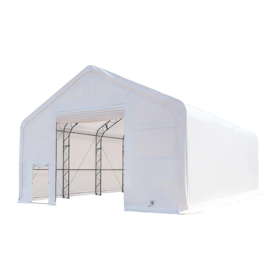
MAIN SPECIFICATIONS : Assembly size : W9.15 x L12 x H6 (m) / 30 x 39.4 x 19.7 (ft) Ridge height : 6m / 19.7 ft Peak clearance : 5.4m / 17.7 ft Front door : 4.27 x 3.96 (m) / 14 x 13 (ft) ... - Page 3 PRIOR TO ASSEMBLY Please go through the whole instruction manual completely. It is very important to follow your local safety regulations and industry standards during installation. Regulations may include but are not limited to : • Safety helmets, protective eyewear, and clothing •...
- Page 4 FRAME STRUCTURE DIAGRAM. 3/27 TOLL FREE:1-877-761-2819 ►www.tmgindustrial.com...
- Page 5 TMG-DT3041 PART LIST PARTS GRAPHICAL DESCRIPTION LENGTH CODE Peak arch tube L2570mm (for 3 middle trusses ) Peak arch tube L2570mm (for front and rear truss) Upper rafter tube L2921mm (for middle trusses) Upper rafter tube L2921mm (for front and rear truss)
- Page 6 Rear door left column W150xL200mm baseplate Rear door right column W150xL200mm baseplate Rear door middle column W150xL200mm baseplate Left baseplate of front door W150xL200mm frame Right baseplate of front door W150xL200mm frame Baseplates for middle truss W260xL480mm Ratchets Expansion bolts φ16x150mm Ceiling cross bar L2083mm...
- Page 7 Left and right upper vertical L1990mm tubes for rear trusses Middle upper vertical tubes L2874mm for rear trusses Front vertical door rail L2625mm (left side lower part) Front vertical door rail L2625mm (right side lower part) Door frame horizontal tube L1982mm (front truss) Door frame middle horizontal...
- Page 8 Sidewall frame steel tension φ6xL4290mm cables Ridge steel tension cables φ6xL3070mm (front and rear trusses) Middle truss crossing steel φ6xL3990mm tension cables Front and rear truss left and φ6xL3900mm right steel cables Tie down straps W38xL800mm (for #7A) Cable connection plate L91mm Pressing plate W20xL2000mm...
- Page 9 Strengthened bolt M12x30mm and nuts Hex bolt and nuts M10x50mm Hex bolt and nuts M10x70mm Braided rope L160m Roof fabric tarp cover W12.6xL18.4m Front truss cover panel W6.2xL9.1m Rear truss fabric cover panel W6.2xL9.1m Front roll up door cover W4.2xL4.6m panel Front fabric tarp secure pin L200mm...
- Page 10 STEP 1 : BASEPLATE POSITIONING AND INSTALLATION. Installation diagram of expansion bolt. PARTS PARTS PART PART CODE CODE 9/27 TOLL FREE:1-877-761-2819 ►www.tmgindustrial.com...
- Page 11 STEP 2 : ASSEMBLE ALL TRUSSES. Front truss. PARTS PARTS PART PART CODE CODE 10/27 TOLL FREE:1-877-761-2819 ►www.tmgindustrial.com...
- Page 12 Rear truss. PARTS PARTS PART PART CODE CODE 11/27 TOLL FREE:1-877-761-2819 ►www.tmgindustrial.com...
- Page 13 Middle trusses. (3 trusses) PARTS PARTS PART PART CODE CODE 24x3 12/27 TOLL FREE:1-877-761-2819 ►www.tmgindustrial.com...
- Page 14 Lay down all (5) trusses on the ground when the assembly is all completed and before moving to next step, and then wrap (#38) around the sharp points of the joint to avoid friction between the fabric and the interface, resulting in fabric damage.
- Page 15 STEP 3 : PUT UP THE FRONT TRUSS. (IT IS SUGGESTED TO USE CRANE FOR HOISTING) PARTS PART CODE 14/27 TOLL FREE:1-877-761-2819 ►www.tmgindustrial.com...
- Page 16 STEP 4 : PUT UP THE REST TRUSSES. Refer to step 3 to put up the rest trusses, connect all purlins (#5) with bolt (#28) and secure all bolts firmly on each span before going to next truss . PARTS PARTS PART...
- Page 17 Repeat above step to put up all other trusses (from 3rd to 5th truss), and connect all purlins. PARTS PARTS PART PART CODE CODE 16/27 TOLL FREE:1-877-761-2819 ►www.tmgindustrial.com...
- Page 18 Tension cable installation . All cables are diagonally installed on each side of the interval. PARTS PARTS PART PART CODE CODE 17/27 TOLL FREE:1-877-761-2819 ►www.tmgindustrial.com...
- Page 19 STEP 5 : FRONT AND REAR TRUSSES TO COMPLETE. Front truss. PARTS PARTS PART PART CODE CODE 18/27 TOLL FREE:1-877-761-2819 ►www.tmgindustrial.com...
- Page 20 Rear truss. PARTS PARTS PART PART CODE CODE 19/27 TOLL FREE:1-877-761-2819 ►www.tmgindustrial.com...
- Page 21 STEP 6 : INSTALL FRONT AND REAR COVER PANELS. Front cover panel. Lift up (#34) cover panel, starting from the center point of the frame (highest ridge point) use ropes (#32) through the grommets to tie the panel to the truss firmly. All grommets need to be tied to the frame as shown.
- Page 22 Rear cover panel. Lift up (#34A) cover panel, starting from the center point of the frame (highest ridge point) use ropes (#32) through the grommets to tie the panel to the truss firmly. All grommets need to be tied to the frame as shown.
- Page 23 Install the front door pressing plate. PARTS PART CODE 22/27 TOLL FREE:1-877-761-2819 ►www.tmgindustrial.com...
- Page 24 STEP 7 : INSTALL MECHANICAL ROLL UP DOORS. Door curtain installation. PARTS PARTS PART PART CODE CODE 23/27 TOLL FREE:1-877-761-2819 ►www.tmgindustrial.com...
- Page 25 Front door installation, please look at the door from inside. The hand winch (#23) comes with a shorter cable, we call it cable (#B). PARTS PARTS PART PART CODE CODE 24/27 TOLL FREE:1-877-761-2819 ►www.tmgindustrial.com...
- Page 26 STEP 8 : INSTALL ROOF COVER. NOTE: The cover must be installed on a windless day. DO NOT attempt to install the cover during windy conditions. PARTS PART CODE 25/27 TOLL FREE:1-877-761-2819 ►www.tmgindustrial.com...
- Page 27 After the cover is installed on the roof, insert the plastic pipe (#37) slowly into the grooves on two ends of the cover (not two sides), and then insert tension tubes (#14,#14A) in the groove on both sides of the cover bottom, Add the water plug (#25) on the 1st tube (#14) to protect the fabric while the tube is going through and add the water plug on the last tube also to keep water away.
-
Page 28: After The Installation
AFTER THE INSTALLATION Walk around and inspect the building periodically to make sure all components are still firmly secured and the whole building is well supported. Check all bolts and nuts as well as all connection points to make sure they are all in good position.
Need help?
Do you have a question about the TMG-DT3041 and is the answer not in the manual?
Questions and answers