Table of Contents
Advertisement
Quick Links
Advertisement
Table of Contents

Related Manuals for Pfeiffer Vacuum HIPACE 80 MINI


Summary of Contents for Pfeiffer Vacuum HIPACE 80 MINI
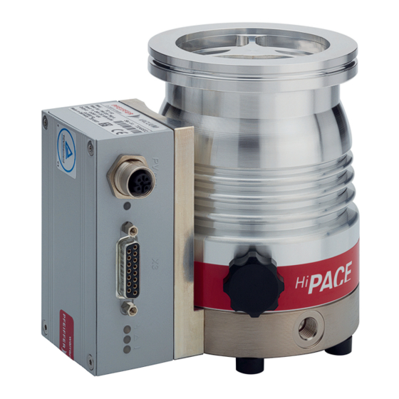
- Page 1 OPERATING INSTRUCTIONS Translation of the Original HIPACE 80 MINI Turbopump...
- Page 2 Dear Customer, Thank you for choosing a Pfeiffer Vacuum product. Your new turbopump is designed to support you by its performance, its perfect operation and without interfering your individual application. The name Pfeiffer Vacuum stands for high-quality vacuum technology, a comprehensive and complete range of top-quality products and first-class service.
-
Page 3: Table Of Contents
Limits of use of product Proper use Foreseeable improper use Personnel qualification 2.7.1 Ensuring personnel qualification 2.7.2 Personnel qualification for maintenance and repair 2.7.3 Advanced training with Pfeiffer Vacuum Product description Function 3.1.1 Cooling 3.1.2 Rotor bearing 3.1.3 Drive Identifying the product 3.2.1 Product types... - Page 4 Table of contents Operating modes 6.2.1 Operation without operating unit 6.2.2 Operation via multi-function connection "X3" 6.2.3 Operation via Pfeiffer Vacuum control unit 6.2.4 Operation via field bus Operation monitoring 6.3.1 Operating mode display via LED 6.3.2 Temperature monitoring Switching off and venting 6.4.1 Switching off...
- Page 5 Factory settings for delayed venting in turbopumps Tbl. 11: Characteristic nominal rotation speeds of the turbopumps Tbl. 12: Troubleshooting turbopumps Tbl. 13: Overview of the spare parts available for the HiPace 80 mini Tbl. 14: Accessories Tbl. 15: Conversion table: Pressure units Tbl. 16: Conversion table: Units for gas throughput Tbl.
- Page 6 Fig. 11: Insert capillary rods and install operating fluid reservoir Fig. 12: Installing and removing the electronic drive unit TC 110 Fig. 13: Spare parts HiPace 80 mini Fig. 14: HiPace 80 mini | TC 110 | DN 63 ISO-K 6/54...
-
Page 7: About This Manual
Keep the manual for future consultation. 1.1 Validity These operating instructions are a customer document of Pfeiffer Vacuum. The operating instructions describe the functions of the named product and provide the most important information for the safe use of the device. The description is written in accordance with the valid directives. The information in these operating instructions refers to the product's current development status. -
Page 8: Pictographs
This section describes all the stickers on the product along with their meanings. Rating plate (example) The rating plate of the turbopump is located on the lower part D-35614 Asslar Berliner Str. 43 HiPace 80 Mini of the vacuum pump. Mod. PM PXX XXX Type 12... -
Page 9: Abbreviations
About this manual 1.3.4 Abbreviations Abbreviation Meaning in this document Flange: Metal-sealed connector in accordance with ISO 3669 Diameter value (in mm) Direct current Nominal diameter as size description Rotation speed value of a vacuum pump (frequency, in rpm or Hz) Handheld Programming Unit. -
Page 10: Safety
Safety 2 Safety 2.1 General safety information The following 4 risk levels and 1 information level are taken into account in this document. DANGER Immediately pending danger Indicates an immediately pending danger that will result in death or serious injury if not observed. ►... - Page 11 ► Take suitable safety precautions on-site for the compensation of the occurring torques. ► Before installing a vibration compensator, you must first of all contact Pfeiffer Vacuum. WARNING Danger to life from poisoning where toxic process media leak from damaged connections Sudden twisting of the turbopump in the event of a fault causes fittings to accelerate.
- Page 12 Safety WARNING Risk of injury due to incorrect installation Dangerous situations may arise from unsafe or incorrect installation. ► Do not carry out your own conversions or modifications on the unit. ► Ensure the integration into an Emergency Off safety circuit. WARNING Danger of cut injuries from unexpected start up.
- Page 13 ► Follow the installation instructions for this turbopump. ► Observe the requirements regarding stability and design of the counter flange. ► Use only original accessories or fixing material approved by Pfeiffer Vacuum for the installation. WARNING Risk of injury caused by the turbopump breaking away with the vibration compensator in the event of a malfunction Sudden jamming of the rotor generates high destructive torques in accordance with ISO 27892.
-
Page 14: Safety Precautions
Safety WARNING Danger to life from poisoning where toxic process media leak from damaged connections Sudden twisting of the turbopump in the event of a fault causes fittings to accelerate. There is the risk of damaging on-site connections (e.g., fore-vacuum line) and resulting leaks. This results in leakage of process media. -
Page 15: Proper Use
● Using of accessories or spare parts that are not listed in these instructions 2.7 Personnel qualification The work described in this document may only be carried out by persons who have appropriate profes- sional qualifications and the necessary experience or who have completed the necessary training as provided by Pfeiffer Vacuum. 15/54... -
Page 16: Ensuring Personnel Qualification
─ Customer with Pfeiffer Vacuum service training ─ Pfeiffer Vacuum service technician 2.7.3 Advanced training with Pfeiffer Vacuum For optimal and trouble-free use of this product, Pfeiffer Vacuum offers a comprehensive range of courses and technical trainings. For more information, please contact Pfeiffer Vacuum technical training. -
Page 17: Product Description
Product description 3 Product description 3.1 Function The turbopump forms a compact unit together with the electronic drive unit. Pfeiffer Vacuum power sup- ply packs can be used for the power supply. Fig. 2: Design of HiPace 80 mini 1 Protective cover... -
Page 18: Product Types
Product description 3.2.1 Product types The product designation of Pfeiffer Vacuum turbopumps from the HiPace series is composed of the family name, the size (which is based on the pumping speed of the vacuum pump) and, if required, an additional feature description. -
Page 19: Transportation And Storage
► Do not stack the products. ► Wear protective equipment, e.g. safety shoes. Recommendation Pfeiffer Vacuum recommends keeping the transport packaging and original protective cov- Safe transport of the product ► Transport the turbopump only within the permissible temperature limits. -
Page 20: Installation
Installation 5 Installation The installation of the turbopump and its fastening is of outstanding importance. The rotor of the turbo- pump revolves at very high speed. In practice it is not possible to exclude the risk of the rotor touching the stator (e.g. due to the penetration of foreign bodies into the high vacuum connection). The kinetic energy released acts on the housing and on the anchoring of the turbopump within fractions of a sec- ond. -
Page 21: Connecting The High Vacuum Side
The total weight of superstructural parts must not exceed the maximum values specified. If the rotor is suddenly blocked, the torques arising from the system and the high vacuum flange must be absorbed. The installation elements for turbo pumps are special designs by Pfeiffer Vacuum. 21/54... -
Page 22: Considering Earthquake Protection
120 ℃ Tbl. 6: Requirements for dimensioning high vacuum connection supplied by customer Important information for correct installation ► Only use the approved mounting kits of Pfeiffer Vacuum for the high vacuum connection of the turbopump. 5.3.2 Considering earthquake protection NOTICE... -
Page 23: Using The Vibration Compensator
4. Observe the fastening of the ISO flanges. 5.3.5 Mounting orientations Pfeiffer Vacuum turbopumps from the HiPace series are suitable for use with dry compressing backing pumps for mounting in all orientations. ► When using oil-sealed backing pumps, avoid backflow from the fore-vacuum range. -
Page 24: Installation Of Iso-K Flange Onto Iso-F
Flange connection ISO-K to ISO-F, bracket screws Connection with bracket screw 1. For the connection of the turbopump, use only the approved mounting kits from Pfeiffer Vacuum. 2. Connect the flange with the components of the mounting kit according to the figure. -
Page 25: Connecting Fore-Vacuum Side
– Tightening torque: 5, 10, 16 ± 1 Nm Connection of stud screw and tapped hole 1. Only use the approved mounting kits from Pfeiffer Vacuum for the connection. 2. Screw the required number of stud screws with the shorter screw-in end into the holes in the counter flange. -
Page 26: Connecting Accessories
Connecting accessory devices to TC ● Use of Pfeiffer Vacuum accessories via the electronic drive unit is enabled via a corre- sponding connection cable or adapter at the “X3” multi-function connection. ● The desired accessory output is configured via RS-485 using Pfeiffer Vacuum control units or a PC. -
Page 27: Connecting The Electrical Supply
► Observe the installation instructions in the operating instructions for the relevant accessory. ► Note the existing configuration of existing connections and control lines. ► Use a Pfeiffer Vacuum control unit for the configuration if needed. 5.6 Connecting the electrical supply... -
Page 28: Establishing Electric Connection
Installation Fig. 8: Example: Connecting the grounding cable Procedure 1. Use the turbopump ground terminal (M4 female thread). 2. Route the connection in accordance with locally applicable provisions. 5.6.2 Establishing electric connection DANGER Danger to life from electric shock Power supply packs that are not specified or are not approved will lead to severe injury to death. ►... - Page 29 5. Insert the connecting cable into the connection "DCout" on the power supply pack and close the bayonet lock. 6. If you are using a Pfeiffer Vacuum control unit: Connect the “RS-485” connector to the control unit using a suitable extension cable.
-
Page 30: Operation
Important settings and function-related variables are programmed ex factory as parameters in the vac- uum pump electronic drive unit. Each parameter has a three-digit number and a description. Parameter- driven operation and control is supported via a Pfeiffer Vacuum control unit, or externally via RS-485 using Pfeiffer Vacuum protocol. -
Page 31: Operating Modes
Notes on operation without control unit 1. Only use the approved Pfeiffer Vacuum connection cables with bridges on the "X3" connection on the electronic drive unit. 2. Only switch on the power supply of the turbopump immediately before operation. -
Page 32: Operation Monitoring
6.3.1 Operating mode display via LED LEDs on the electronic drive unit show the basic operating states of the vacuum pump. A differentiated error and warning display is only possible for operation with the Pfeiffer Vacuum control unit or a PC. Symbol... -
Page 33: Venting
General information for fast venting We recommend fast venting of larger volumes in 4 steps. 1. Use a Pfeiffer Vacuum venting valve for the turbopump, or match the valve cross-section to the size of the recipient and maximum venting rate. -
Page 34: Maintenance
5. Change the operating fluid reservoir at least every 4 years. 6. Have Pfeiffer Vacuum Service replace the rotor bearing of the turbopump at least every 4 years. 7. Consult with Pfeiffer Vacuum Service about shorter maintenance intervals for extreme loads or im- pure processes. -
Page 35: Replace Operating Fluid Reservoir
● When ordering spare parts, make sure you use the correct pump article number and the operating fluid reservoir. ● This information can be found on the pump rating plate. You can find the safety data sheet in the Pfeiffer Vacuum Download Center. Prerequisites ● Turbopump off ●... -
Page 36: Assembling Operating Fluid Reservoir
Maintenance Fig. 10: Removing the operating fluid reservoir 1 Housing cover Capillary rods (6×) 2 Torx screws Operating fluid reservoir 3 Rubber-metal bumper Protective cover 4 O-ring Removing the operating fluid reservoir 1. Wear laboratory gloves to avoid skin contact. 2. -
Page 37: Replacing Electronic Drive Unit
Maintenance Fig. 11: Insert capillary rods and install operating fluid reservoir 1 Capillary rods (6×) Housing cover 2 Operating fluid reservoir Rubber-metal bumper 3 O-ring Torx screws Assembling operating fluid reservoir 1. Insert the new capillary rods using tweezers. 2. Insert the operating fluid reservoir up to the stop in the pump base. –... -
Page 38: Confirming Speed Specification
Maintenance Backing up settings made by the customer The factory operating parameters are always preset in replacement units. All settings made by the customer to the original electronic drive unit are lost when it is replaced. To preserve your custom settings, you have the following options: 1. -
Page 39: Tbl. 11: Characteristic Nominal Rotation Speeds Of The Turbopumps
5. Set the parameter [P:777] to the required value of the nominal rotation speed in Hertz. Alternative to adjusting the nominal rotation speed confirmation A Pfeiffer Vacuum SpeedConfigurator for the one-time immediate setting of parameter [P:777] is included with the replacement units. -
Page 40: Decommissioning
2. Clean the turbopump exterior with a lint-free cloth and a little isopropanol. 3. If necessary, arrange for Pfeiffer Vacuum Service to completely clean the turbopump. 4. Observe the total running time of the turbopump and if necessary, arrange for Pfeiffer Vac- uum Service to replace the bearing. -
Page 41: Recycling And Disposal
● Help to reduce the wastage of natural resources. ● Prevent contamination. 9.1 General disposal information Pfeiffer Vacuum products contain materials that you must recycle. ► Dispose of our products according to the following: – Iron – Aluminium –... -
Page 42: Malfunctions
► Follow the installation instructions for this turbopump. ► Observe the requirements regarding stability and design of the counter flange. ► Use only original accessories or fixing material approved by Pfeiffer Vacuum for the installation. WARNING Risk of injury caused by the turbopump breaking away with the vibration compensator in the event of a malfunction Sudden jamming of the rotor generates high destructive torques in accordance with ISO 27892. -
Page 43: Tbl. 12: Troubleshooting Turbopumps
● Reduce the process gas load. ● Rotor not running ● Check the turbopump for noise development smoothly, defective ● Contact Pfeiffer Vacuum Service. bearing ● Run-up time setpoint ad- ● Use a control unit to extend the set value run-up justed too low time [P:700]. -
Page 44: Service Solutions By Pfeiffer Vacuum
We are always focused on perfecting our core competence – servicing of vacuum components. Once you have purchased a product from Pfeiffer Vacuum, our service is far from over. This is often exactly where service begins. Obviously, in proven Pfeiffer Vacuum quality. - Page 45 Service solutions by Pfeiffer Vacuum 5. Prepare the product for transport in accordance with the provisions in the contamination declaration. a) Neutralize the product with nitrogen or dry air. b) Seal all openings with blind flanges, so that they are airtight.
-
Page 46: Spare Parts Hipace 80 Mini
TC 110 plate tion panel Operating fluid reservoir PM 183 900 -T incl. capillary rods and O- ring Tbl. 13: Overview of the spare parts available for the HiPace 80 mini 46/54... -
Page 47: Accessories
Optionally with splinter shield or protective screen. Power supply packs and control units Power supply packs for optimal voltage supply of Pfeiffer Vacuum products are characterized by their compact size and adapted power supply with maximum reliability. Control units are used to check and adjust operating parameters. -
Page 48: Tbl. 14: Accessories
Accessories Designation HiPace 80 mini, DN 63 ISO‑K Mounting kit for HiPace 60/80, DN 63 ISO-K, including coated cen- PM 016 512 -T tering ring with integrated protection screen and claw grips Mounting kit for DN 63 ISO-K to ISO-F, with collar flange, coated... -
Page 49: Technical Data And Dimensions
Technical data and dimensions 14 Technical data and dimensions 14.1 General This section describes the basis for the technical data of Pfeiffer Vacuum turbopumps. Technical data Maximum values refer exclusively to the input as a single load. ● Specifications according to PNEUROP committee PN5 ●... -
Page 50: Tbl. 17: Hipace 80 Mini | Dn63 Iso-K
IP44, Type 12 Integral leak rate 1 · 10 Pa m³/s Relative humidity of air 5 – 85 %, non-condensing Shipping and storage temperature -25 – 55 °C Weight 2.1 kg Tbl. 17: HiPace 80 mini | DN63 ISO-K 50/54... -
Page 51: Dimensions
Technical data and dimensions 14.3 Dimensions 92.5 DN63 ISO-K M5 - 10 deep (4x) 37.5 G1/4” Fig. 14: HiPace 80 mini | TC 110 | DN 63 ISO-K Dimensions in mm 51/54... -
Page 52: Ec Declaration Of Conformity
DIN EN 61010-1 : 2020 DIN EN IEC 63000 : 2019 The authorized representative for the compilation of technical documents is Mr. Tobias Stoll, Pfeiffer Vacuum GmbH, Berliner Straße 43, 35614 Asslar, Germany. Signature: Pfeiffer Vacuum GmbH Berliner Straße 43... -
Page 53: Declaration Of Conformity
ISO 21360-4:2018 IEC 61010-1+A1:2010 IEC 63000:2018 The manufacturer's authorized representative in the United Kingdom and the authorized agent for compiling the technical documentation is Pfeiffer Vacuum Ltd, 16 Plover Close, In- terchange Park, MK169PS Newport Pagnell. Signature: Pfeiffer Vacuum GmbH Berliner Straße 43...
Need help?
Do you have a question about the HIPACE 80 MINI and is the answer not in the manual?
Questions and answers