Pfeiffer Vacuum HIPACE 800 Operating Instructions Manual
Turbopump
Hide thumbs
Also See for HIPACE 800:
- Operating instructions manual (64 pages) ,
- Operating instructions manual (116 pages) ,
- Operating instructions manual (26 pages)

Subscribe to Our Youtube Channel
Related Manuals for Pfeiffer Vacuum HIPACE 800


Summary of Contents for Pfeiffer Vacuum HIPACE 800
- Page 1 OPERATING INSTRUCTIONS Translation of the original instructions HIPACE 800 Turbopump...
-
Page 2: Table Of Contents
Table of contents Table of contents About this manual ..........4 1.1 Validity. - Page 3 12.1 HiPace 800, 48 V DC ........37 12.2 Differences at HiPace 800, 24 V DC......38 Technical data and dimensions .
-
Page 4: About This Manual
About this manual Validity This operating manual is for customers of Pfeiffer Vacuum. It describes the functioning of the designated product and provides the most important information for safe use of the unit. The description follows applicable EU guidelines. All information provided in this operating manual refers to the current state of the product's development. -
Page 5: Pictographs
About this manual 1.2.2 Pictographs Prohibition of an action to avoid any risk of accidents, the disregarding of which may result in serious accidents Warning of a displayed source of danger in connection with operation of the unit or equipment Command to perform an action or task associated with a source of dan- ger, the disregarding of which may result in serious accidents Important information about the product or this document... -
Page 6: Safety
Installation and operation of accessories Pfeiffer Vacuum pumps can be equipped with a series of adapted accessories. The in- stallation, operation and maintenance of connected devices are described in detail in the operating instructions of the individual components. -
Page 7: Protective Equipment
Safety ● Do not loosen any plug connection during operations. ● Wait for the rotor to reach standstill before peforming work on the high vacuum flange. ● Keep leads and cables well away from hot surfaces (> 70 °C). ● Never fill or operate turbopump with cleaning agent. ●... -
Page 8: Improper Use
Safety ● The vacuum pump may only be used to generate a vacuum. ● Only operate the turbopump with an approved backing pump. Improper use Improper use will cause all claims for liability and warranties to be forfeited. Improper use is defined as usage for purposes deviating from those mentioned above, especially: ●... -
Page 9: Transport And Storage
Transport and storage Transport and storage Transport Reuse the transport container of the vacuum pump. – Transport or ship vacuum pumps in the original packing preferably. Only remove the protective covers from the high vacuum and the fore-vacuum side immediately before connection. -
Page 10: Product Description
Fig. 1: Example for a rating plate 4.1.3 Variants ● HiPace 800 with TC 400 and 24 V DC ± 5 % ● HiPace 800 with TC 400 and 48 V DC ± 5 % 4.1.4 Scope of delivery ● Turbopump with electronic drive unit ●... -
Page 11: Function
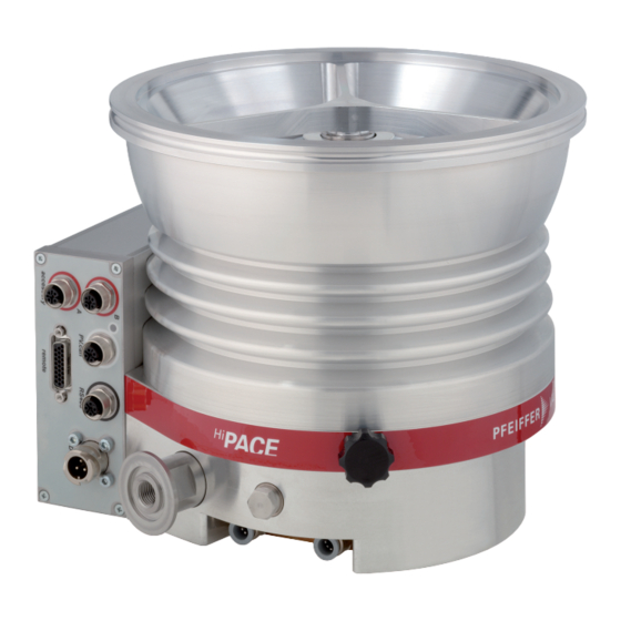
Product description Function The turbopump HiPace 800 forms a complete unit together with the electronic drive unit TC 400. For the voltage supply only Pfeiffer Vacuum power supplies may be used (e.g.TPS or DCU). remote Fig. 2: View of HiPace 800 with TC 400... -
Page 12: Range Of Application
Product description Range of application The pump HiPace 800 must be installed and operated under the following ambient con- ditions: Installation location weather protected (indoors) Protection category IP 54 Protection class Temperature +5 °C to +35 °C with air cooling +5 °C to +40 °C with water cooling... -
Page 13: Installation
Only use approved original parts from Pfeiffer Vacuum (Accessories) for the installa- tion. Installation and operation of accessories Pfeiffer Vacuum pumps can be equipped with a series of adapted accessories. The in- stallation, operation and maintenance of connected devices are described in detail in the operating instructions of the individual components. -
Page 14: Mounting Orientation
5.2.2 Use of a splinter shield or protection screen Pfeiffer Vacuum centering rings with splinter shield or protection screen in the high vac- uum flange protect the turbopump against foreign bodies coming from the chamber. Thus, the pumping speed of the pump is reduced. - Page 15 Installation To avoid contamination via the fore-vacuum line when using oil-sealed backing pumps the fore-vacuum flange should always point vertically downward (± 25°). 25° max Fig. 4: Recommended orientation of the fore-vacuum flange The maximum axial loading capacity of the high vacuum flange is 1000 N (equals 100 kg).
-
Page 16: Installing The High Vacuum Flange
Twisting or tearing-off is possible in case the rotor is suddenly blocked due to the fas- tening of pumps on a vacuum chamber with different flange variants. Use only the correct mounting kit from Pfeiffer Vacuum. Pfeiffer Vacuum will not accept any liability for all damages resulting from impermis- sible fastening. NOTICE... -
Page 17: Installation Of Iso-K Flange With Iso-F Flange
"stud screw and threaded hole," and "stud screw and through hole". For the installation the following components are exclusively authorized: ● the valid mounting kit of the Pfeiffer Vacuum accessories programme ● mounting materials including protection screen or splinter shield are optionally avail-... -
Page 18: Installation Of Iso-F With Iso-F Flange
"stud screw and threaded hole," and "stud screw and through hole". For the installation the following components are exclusively authorized: ● the valid mounting kit of the Pfeiffer Vacuum accessories programme ● mounting materials including protection screen or splinter shield are optionally avail-... -
Page 19: Installation Of Cf- Flanges
The connection types for installation of CF to CF flange are "hexagon screw and through hole", "stud screw and threaded hole" as well as "stud screw and through hole". ● the valid mounting kit of the Pfeiffer Vacuum accessories programme ● A copper seal ●... -
Page 20: Connecting The Fore-Vacuum Side
Installation Connecting the fore-vacuum side Recommendation: As backing pump, use a suitable vacuum pump from the Pfeiffer Vacuum programme. WARNING Damage to health due to poisonous gases Process gases can damage health and contaminate the environment. Safely lead away the gas emission from the backing pump! ... -
Page 21: Connections To The Turbopump
Detailed description for function, configuration and operation with the respective connec- tion panel are given in the specific operating instructions for the electronic drive unit. 5.6.2 Earthing Pfeiffer Vacuum recommends to connect an appropriate earthing wire to derive applica- tive interferences. Fig. 6: Installing the earthing connection 5.6.3... -
Page 22: Accessory Connection
To connect two units to one accessory connection, use the appropriate Y-Connector from the Pfeiffer Vacuum range of accessories. Connect the adapter to the appropriate red-coded connection on the TC 400. Settings can be made via the interfaces of the TC 400 (remote, RS-485, Profibus or... -
Page 23: Air Cooling
Default for air cooling is "accessory A1". 5.7.2 Venting valve The Pfeiffer Vacuum venting valve is used for automatic venting in case of shut-down or power failure. The permissible connection pressure is max. 1500 hPa absolute. Fig. 8:... -
Page 24: Heating Jacket
● When operating the pump with more than 50 % of the maximum gas throughput, seal- ing gas must be used to ensure rotor cooling. ● The sealing gas flow rate amounts 12-15 sccm for the HiPace 800. Sealing gas supply with control valve Fig. - Page 25 Installation ● When using a casing heating and a water cooling unit the temperature of the connect- ed flange of the vacuum chamber must not exceed 120 °C. ● The maximum permissible rotor temperature for the turbopump is 90 °C. If high tem- peratures arise for process reasons, the radiated heat input must not exceed 4.2 W.
-
Page 26: Water Cooling
5.7.5 Water cooling The turbopumps HiPace 800 with TC 400 have water cooling as standard equipment. ● In case of increased backing pressure (> 0.1 hPa) and/or operation with high gas throughputs, either air or water cooling may be used. -
Page 27: Operation
Pumping of gases with a higher molecular mass in the wrong gas mode can lead to de- struction of the pump. Ensure the gas mode is correctly set. Contact Pfeiffer Vacuum before using gases with a greater molecular mass (> 80). Operation modes The following operation modes are available: ●... -
Page 28: Operation Without Operating Unit
Consider the following manuals for the operation via remote control: ● Operating instructions "Electronic drive unit TC 400" 6.3.3 Operation with DCU or HPU Consider the following manuals for the operation via Pfeiffer Vacuum display and con- trol units: ● Operating instructions "DCU" ● Operating instructions "HPU"... -
Page 29: Operation Display Via Led
– The valve cross section for the venting rate of 15 hPa/s must be adapted to the size of the vacuum chamber. – For small vacuum chambers, use the Pfeiffer Vacuum venting valve. Then vent with an additional venting valve of any desired size. -
Page 30: Maintenance / Replacement
Decontaminate affected parts before carrying out maintenance work. NOTICE Disclaimer of liability Pfeiffer Vacuum accepts no liability for personal injury or material damage, losses or op- erating malfunctions due to improperly performed maintenance. The liability and war- ranty entitlement expires. - Page 31 Maintenance / replacement Fig. 13: Assembly / Disassembly of the operating fluid reservoir End cover Poroplast rod Allen head screw Operating fluid reservoir Injection tip O-ring Screw out the Allen head screws (3x) from the end cover at the bottom of the tur- bopump.
-
Page 32: Replacing The Electronic Drive Unit
Maintenance / replacement Replacing the electronic drive unit NOTICE Damages to the pump and drive Even after the mains power is switched off, the subsequently running pump delivers electric power to the electronic drive unit. There is a danger of electric body contact by premature separating the pump from the electronic drive unit. -
Page 33: Decommissioning
Check turbopump for contamination and moisture. Clean the turbopump externally with a lint-free cloth and little industrial alcohol. If necessary, have Pfeiffer Vacuum Service clean the turbopump completely. If necessary, have the bearings replaced. Take into account the total running time. -
Page 34: Malfunctions
Reset via pin 13 on the "REMOTE" connection Differentiated malfunction display is possible via RS-485 Contact the Pfeiffer Vacuum Service If no Pfeiffer Vacuum display and control unit is available, please contact the Pfeiffer Vacuum Ser- vice. -
Page 35: 10 Service
The following steps are necessary to ensure a fast, smooth servicing process: Download the forms "Service Request" and "Declaration on Contamination". Fill out the "Service Request" form and send it by fax or e-mail to your Pfeiffer Vacuum service address. -
Page 36: Spare Parts Hipace 800
Spare parts HiPace 800 11 Spare parts HiPace 800 Item Designation Order number Notes Pieces Order qty Operating fluid reservoir PM 143 452 -T incl. Poroplast rods Electronic drive unit TC 400 according to the rating plate depends on the connection panel Mating plug "remote"... -
Page 37: 12 Accessories
Designation DN 200 ISO-K DN 200 CF-F DN 200 ISO-F Mounting kit for HiPace 800, DN 200 ISO-K, including coated centering PM 016 354 -T ring and bracket screws Mounting kit for HiPace 800, DN 200 ISO-K, including coated centering... -
Page 38: 12.2 Differences At Hipace 800, 24 V Dc
PTR 72 100 IKT 011, Digital Cold Cathode Sensor, high current PT R73 100 PT R73 100 PT R73 100 12.2 Differences at HiPace 800, 24 V DC Designation DN 200 ISO-K DN 200 CF-F DN 200 ISO-F TPS 310, mains pack for wall/standard rail fitting... -
Page 39: 13 Technical Data And Dimensions
Technical data and dimensions 13 Technical data and dimensions 13.1 General Basic principles for the Technical Data of Pfeiffer Vacuum Turbopumps: Maximum values refer exclusively to the input as a single load. ● Recommendations of PNEUROP committee PN5 ● ISO 21360; 2007: "Vacuum technology - Standard methods for measuring vacuum- pump performance - General description"... -
Page 40: 13.3 Differences At Hipace 800, 24 V Dc
4.2 W 4.2 W Permissible magnetic field max. 6 mT 6 mT 6 mT Interfaces RS-485, Remote RS-485, Remote RS-485, Remote 13.3 Differences at HiPace 800, 24 V DC ® ® ® Flange (in) HiPace HiPace HiPace > 800 Flange (in) -
Page 41: 13.4 Dimensions
13.4 Dimensions Ø 8 DN 200 ISO-K DN 25 ISO-KF / G 1/4“ M8 (6x) 145.5 Fig. 15: HiPace 800, DN 200 ISO-K Ø8 DN 25 ISO-KF / G 1/4“ DN 200 ISO-F M8 (6x) 145.5 Fig. 16: HiPace 800, DN 200 ISO-F Ø8... -
Page 42: Declaration Of Conformity
● Machinery 2006/42/EC (Annex II, no. 1 A) ● Electromagnetic Compatibility 2014/30/EU The agent responsible for compiling the technical documentation is Mr. Helmut Bern- hardt, Pfeiffer Vacuum GmbH, Berliner Straße 43, 35614 Aßlar. HiPace 800 Harmonised standards and national standards and specifications which have been ap-... - Page 43 VACUUM SOLUTIONS FROM A SINGLE SOURCE Pfeiffer Vacuum stands for innovative and custom vacuum solutions worldwide, technological perfection, competent advice and reliable service. COMPLETE RANGE OF PRODUCTS From a single component to complex systems: We are the only supplier of vacuum technology that provides a complete product portfolio.
Need help?
Do you have a question about the HIPACE 800 and is the answer not in the manual?
Questions and answers