
Related Manuals for Pfeiffer Vacuum HILOBE 8104


Summary of Contents for Pfeiffer Vacuum HILOBE 8104
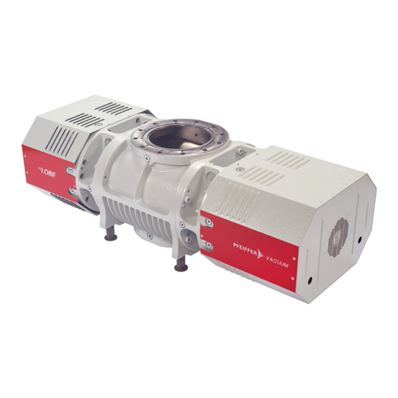
- Page 1 OPERATING INSTRUCTIONS Translation of the Original HILOBE 8104 | 11004 | 14004 Roots pump...
- Page 2 Dear Customer, Thank you for choosing a Pfeiffer Vacuum product. Your new roots pump should support you in your individual application with full performance and without malfunctions. The name Pfeiffer Vacuum stands for high-quality vacuum technology, a comprehensive and complete range of top-quality products and first-class service.
-
Page 3: Table Of Contents
Connecting temperature sensors and fan Connecting accessories Connect to mains power supply Interfaces "Remote" interface 6.1.1 Voltage output 6.1.2 Inputs 6.1.3 Outputs 6.1.4 RS-485 Interface RS-485 Pfeiffer Vacuum protocol for RS-485 interface 6.3.1 Telegram frame 6.3.2 Telegram description 6.3.3 Telegram example 1 3/64... - Page 4 Reference value inputs Additional parameter for the DCU Operation Commissioning the vacuum pump Switching on the vacuum pump Configuring the connections with the Pfeiffer Vacuum parameter set Operating modes 8.4.1 Normal operation 8.4.2 Stand-by operation 8.4.3 Rotation speed setting mode Operation monitoring 8.5.1 Operating mode display via LED...
- Page 5 List of tables List of tables Tbl. 1: Stickers on the product Tbl. 2: Abbreviations used Tbl. 3: Permissible ambient conditions Tbl. 4: Features of the roots pumps Tbl. 5: Required properties of the power supply cable Tbl. 6: Plug arrangement of the D-Sub socket, 15-pin Tbl.
- Page 6 Fig. 15: Replace the filter mat of the fan Fig. 16: Draining lubricant Fig. 17: Filling with lubricant Fig. 18: HiLobe 8104, HiLobe 11004, HiLobe 14004 | DN 250 Fig. 19: Switch box with electronic drive unit RC 15000 6/64...
-
Page 7: About This Manual
Keep the manual for future consultation. 1.1 Validity This operating instructions is a customer document of Pfeiffer Vacuum. The operating instructions de- scribe the functions of the named product and provide the most important information for the safe use of the device. The description is written in accordance with the valid directives. The information in this op- erating instructions refers to the product's current development status. -
Page 8: Pictographs
About this manual 1.3.2 Pictographs Pictographs used in the document indicate useful information. Note Qr code is linked to further online information. We recommend viewing on a tablet computer. Pay attention to the amount of data that is generated. 1.3.3 Stickers on the product This section describes all the stickers on the product along with their meaning. -
Page 9: Abbreviations
Standard for a physical interface for asynchronous serial data transmission (Recom- mended Standard) remote 15-pin D-Sub connecting socket on the control panel of the switch box Short-circuit capacity Fluoropolymer rubber Frequency converter Operating instructions Service instructions Pfeiffer Vacuum Tbl. 2: Abbreviations used 9/64... -
Page 10: Safety
Safety 2 Safety 2.1 General safety information The following 4 risk levels and 1 information level are taken into account in this document. DANGER Immediately pending danger Indicates an immediately pending danger that will result in death or serious injury if not observed. ►... - Page 11 Safety Risks during installation DANGER Danger to life from electric shock Touching exposed and voltage-bearing elements causes an electric shock. Improper connection of the mains supply leads to the risk of touchable live housing parts. There is a risk to life. ►...
- Page 12 ► Install suitable touch protection if the vacuum pump is accessible to untrained persons. ► Allow the vacuum pump to cool down before carrying out any work. ► Contact Pfeiffer Vacuum for suitable touch protection in system solutions. Risks during operation...
-
Page 13: Safety Precautions
Safety Risks during maintenance, decommissioning, disposal and in event of malfunctions WARNING Danger to life from electric shock during maintenance and service work There is a danger to life from electric shock when making contact with live components that still exist after the vacuum pump has been switched off. -
Page 14: Limits Of Use
Safety General safety precautions ► Do not expose body parts to the vacuum. ► Observe the safety and accident prevention regulations, if necessary wear personal protective equipment. ► Check all safety measures at regular intervals. ► Always ensure a secure connection to the earthed conductor (PE), protection class I. ►... -
Page 15: Proper Use
► Adhere to the installation, commissioning, operating, and maintenance instructions. ► Use only accessory parts recommended by Pfeiffer Vacuum. 2.6 Foreseeable misuse Misuse of the product invalidates all warranty and liability claims. Any use that is counter to the purpose of the product, whether intentional or unintentional, is regarded as misuse. -
Page 16: Personnel Qualification For Maintenance And Repair
2.7.2 Personnel qualification for maintenance and repair Adequately trained individuals are: ● Maintenance level 1 ─ Customer with technical education ─ Pfeiffer Vacuum service technician ● Maintenance level 3 ─ Pfeiffer Vacuum service technician 16/64... -
Page 17: Product Description
Lubrication is limited to the two bearing and gear chambers which are arranged separately from the suction chambers. Scan the QR code or click here and see how Pfeiffer Vacuum roots pumps work. Fig. 3: Design, vertical direction of flow 1 Filler screw... -
Page 18: Drive
The vacuum pump is suitable for vertical direction of flow. 3.2 Identifying product To ensure for a clear identification of the product when communicating with Pfeiffer Vacuum, always keep all of the information on the rating plate to hand. The following information is shown on the rating plates: ●... -
Page 19: Product Features
Product description 3.3 Product features Pump type Nominal pumping speed Inlet/direction of flow HiLobe 8104 top/vertical 2700 – 8120 m HiLobe 11004 top/vertical 2700 – 10830 m HiLobe 14004 top/vertical 2700 – 13540 m Tbl. 4: Features of the roots pumps 3.4 Scope of delivery... -
Page 20: Transportation And Storage
● Fill the gear and bearing chambers with lubricant only once the final installation posi- tion is reached. Packing Pfeiffer Vacuum recommends storing the transport packaging. General notes 1. Observe weight specified on the rating plate. 2. Where possible, always transport or ship the roots pump in its original packaging. -
Page 21: Storing Vacuum Pump
Neither the suction chamber nor the pistons in the roots pump in the roots pump interior are provided with corrosion protection. Storage Pfeiffer Vacuum recommends storing the products in their original transport packaging. Procedure 1. Vacuum-seal both connection flanges. 2. Store the roots pump only in dry, dust-free rooms, within the specified ambient conditions. -
Page 22: Installation
► Install suitable touch protection if the vacuum pump is accessible to untrained persons. ► Allow the vacuum pump to cool down before carrying out any work. ► Contact Pfeiffer Vacuum for suitable touch protection in system solutions. General notes for the installation of vacuum components ►... -
Page 23: Filling Up Lubricant
► Please refer to rating plate of the vacuum pump for type and quantity of intended lubricant. – Only the lubricant used during initial installation is permissible. ► Contact Pfeiffer Vacuum if you want to use another type of lubricant. Permissible lubricants ●... - Page 24 Installation Required tools ● Allen key, WAF 8 ● Ring spanner, WAF 27 Required aids ● Collection receptacle Fig. 8: Filling up lubricant 1 Filler screws Drain screw 2 Fill level limiter Filling up lubricant The oil chambers of the roots pump are each equipped with a fill level limiter. A riser tube limits the max.
-
Page 25: Connecting Vacuum Side
Installation 5.4 Connecting vacuum side WARNING Risk of crushing from rotating parts Fingers and hands may be caught by rotating pistons within the connection flange. This results in se- vere injuries. ► Keep limbs out of the reach of the roots pump. NOTICE Property damage from intake of solid particles During commissioning, there is a risk of damage to the suction chamber from dirt from the system or... -
Page 26: Connecting The Fore-Vacuum Side
● Ring spanner, WAF 16 with flange DN 250 ISO-F ● Ring spanner, WAF 30 with flange DN 250 PN16 Condensate separator Pfeiffer Vacuum recommends installing a condensate separator, with condensate drain at the lowest point of the exhaust line. Connecting the fore-vacuum side 1. -
Page 27: Connecting Switch Box
Installation 5.6 Connecting switch box CAUTION Electric shock and damage to the vacuum pump and electronic drive unit due to improper connection and disconnection of components With existing power supply connection to the switch box, there is a risk of electric shock when making contact with the motor connecting plug. -
Page 28: Connecting Accessories
2. Connect the connecting cables of both fans to the matching connections (Fan 1 and Fan 2) on the switch box. 5.8 Connecting accessories Installation and operation of accessories Pfeiffer Vacuum offers a series of special, compatible accessories for its roots pumps. ● Information and ordering options for approved accessories can be found online. -
Page 29: Tbl. 5: Required Properties Of The Power Supply Cable
Installation WARNING Risk of fatal injury due to electric shock on account of incorrect installation The device's power supply uses life-threatening voltages. Unsafe or improper installation can lead to life-threatening situations from electric shocks obtained from working with or on the unit. ►... -
Page 30: Interfaces
The 15-pin sub-D connection with the "remote" designation offers the possibility to operate the electron- ic drive unit via remote control. The following specifications are the factory settings for the electronic drive unit. They can be configured with the Pfeiffer Vacuum parameter set. ► Utilize the screened plug and cable. -
Page 31: Inputs
6.1.4 RS-485 Pin 13 and pin 14 You can connect a Pfeiffer Vacuum display and control unit (DCU or HPU) or an external PC via pin 13 and pin 14 on the D-sub connection of the electronic drive unit. 6.2 Interface RS-485... -
Page 32: Pfeiffer Vacuum Protocol For Rs-485 Interface
Interfaces The interface with the designation “RS-485” is intended for the connection of a Pfeiffer Vacuum display and control unit (DCU or HPU) or an external computer. The connections are galvanically safe and are isolated from the maximum supply voltage for the electronic drive unit. -
Page 33: Telegram Description
● Group address "9xx" for all identical units (no response) ● Global address "000" for all units on the bus (no response) Action according to telegram description n2 – n0 Pfeiffer Vacuum parameter numbers I1 – I0 Data length dn to d0 dn – d0 Data in the respective data type (see chapter “Data types”, page... -
Page 34: Data Types
Interfaces --> ASCII 6.3.5 Data types Data type Description Length Example l1 – l0 boolean_old Logical value (false/true) 000000 is equivalent to false 111111 is equivalent to true u_integer Positive whole number 000000 to 999999 u_real Positive fixed point number 001571 corresponds with 15.71 string Any character string with 6 charac-... -
Page 35: Parameter Set
Important settings and function-related characteristics are factory-programmed into the electronic drive unit as parameters. Each parameter has a three-digit number and a description. The use of the parame- ter is possible via Pfeiffer Vacuum displays and control panels, or externally via RS-485 using Pfeiffer Vacuum protocol. -
Page 36: Status Requests
Parameter set Display Designations Functions Data Unit min. max. type cess fault type VentOnOff 0 = off 1 = on valid only for pumps with CtrlViaInt Operate via in- 1 = remote terface 2 = RS-485 4 = PV.can 32 = Keys on the front pan- 255 = Interface selection IntSelLckd Interface selec-... -
Page 37: Reference Value Inputs
The basic parameter set is set in the electronic drive unit ex-factory. For controlling con- nected external components (e.g. vacuum measuring instruments), additional parameters (extended parameter set) are available in the corresponding Pfeiffer Vacuum display and control panels. ● Refer to the corresponding operating instructions of the respective components. -
Page 38: Operation
► Install suitable touch protection if the vacuum pump is accessible to untrained persons. ► Allow the vacuum pump to cool down before carrying out any work. ► Contact Pfeiffer Vacuum for suitable touch protection in system solutions. Before switching on 1. -
Page 39: Operating Modes
The control is carried out by means of "PLC level". Operate with peripheral devices DCU, HPU or PC 1. When handling the Pfeiffer Vacuum display and control unit, observe the respective operating in- structions: – "DCU" operating instructions available from the Download Center. -
Page 40: Normal Operation
The electronic drive unit regulates automatically to the next valid value. Pfeiffer Vacuum recommends stand-by operation for the vacuum pump during breaks in processes or production. ● If stand-by mode is active, the electronic drive unit reduces the rotation speed of the vacuum pump in the range of 25 to 100% of the nominal speed. -
Page 41: Temperature Monitoring
Operation Symbol LED status Display Meaning Green without current On, flashing "Pump OFF" On, constant "Pump ON" Yellow no warning On, constant Warning No errors On, constant Error Tbl. 15: Meaning of the LEDs 8.5.2 Temperature monitoring Depending on the sensor type, temperature thresholds for warning and malfunction messages are stor- ed immutably in the parameter set of the electronic drive unit. - Page 42 3. Vent the vacuum pump via the intake side to avoid the gas backstreaming. 4. Switch off the process- and pump-specific media supply (e.g. the sealing gas supply). Alternative: Switch off via the Pfeiffer Vacuum parameter ► Set the parameter [P:010] to the value "0".
-
Page 43: Maintenance
► Keep limbs out of the reach of the roots pump. NOTICE Danger of property damage from improper maintenance Unprofessional work on the vacuum pump will lead to damage for which Pfeiffer Vacuum accepts no liability. ► We recommend taking advantage of our service training offering. -
Page 44: Tbl. 16: Maintenance Intervals
We recommend that Pfeiffer Vacuum Service (PV) carry out maintenance work at level 3. Pfeiffer Vacuum will be released from all warranty and liability claims if maintenance work is not carried out properly. This also applies wherever parts other than original spare parts are used. -
Page 45: Cleaning Air Filter
Maintenance 9.3 Cleaning air filter Fig. 15: Replace the filter mat of the fan 1 Filter mats Louvre grille Required tools ● Screwdriver Clean or replace filter 1. Carefully lever off the louver grille using a screwdriver. 2. Remove the filter mats. 3. -
Page 46: Draining Lubricant
The usable life may deviate from the reference value specified depending on thermic and chemical loads, or due to penetrating process media in gear and bearing chambers. Safety data sheets You can obtain the safety data sheets for lubricants from Pfeiffer Vacuum on request, or from the Pfeiffer Vacuum Download Center. - Page 47 Maintenance Required tools ● Allen key, WAF 8 ● Ring spanner, WAF 27 Fig. 17: Filling with lubricant 1 Filler screws Drain screw 2 Fill level limiter Filling with lubricant 1. Screw the fill level limiter back in. 2. Place a collection receptacle under each drain. 3.
-
Page 48: Decommissioning
The useful life of the lubricant is limited (max. 2 years). Prior to recommissioning, carry out the follow- ing operations following inactivity of 2 years or more: ► Observe the maintenance instructions – consult Pfeiffer Vacuum where necessary. ► Change the lubricant. -
Page 49: Recycling And Disposal
– Potentially contaminated components that come into contact with media 11.2 Dispose of HiLobe roots pumps Pfeiffer Vacuum roots pumps from the HiLobe series contain materials that you must recycle. 1. Fully drain the lubricant. 2. Disconnect the electronic drive unit. -
Page 50: Malfunctions
● Suction chamber dirty ● Switch off the vacuum pump immedi- ately. ● Clean suction chamber. ● If necessary, contact Pfeiffer Vacuum Service. Vacuum pump switches off after a ● Thermal protection switch of the ● Determine the cause and eliminate... -
Page 51: Error Codes
1. Read out error codes via Pfeiffer display and control units or a PC. 2. Remove the cause of the malfunction. 3. Reset the malfunction message with parameter [P:009]. – Use preconfigured quick keys with the symbol or display tiles on Pfeiffer Vacuum display and control units. Error Problem... -
Page 52: Warning And Error Messages When Operating With Dcu
Err173 Motor excess current ● Suction chamber dirty ● Check the vacuum pump (FC) ● Short-circuit ● Contact Pfeiffer Vacuum Service Err177 Overload (FC) ● Suction chamber contaminated – ● Check the vacuum pump Vacuum pump clogged over a ● Contact Pfeiffer Vacuum Service longer period or overloaded ●... -
Page 53: Service Solutions By Pfeiffer Vacuum
We are always focused on perfecting our core competence – servicing of vacuum components. Once you have purchased a product from Pfeiffer Vacuum, our service is far from over. This is often exactly where service begins. Obviously, in proven Pfeiffer Vacuum quality. - Page 54 Service solutions by Pfeiffer Vacuum 5. Prepare the product for transport in accordance with the provisions in the contamination declaration. a) Neutralize the product with nitrogen or dry air. b) Seal all openings with blind flanges, so that they are airtight.
-
Page 55: Ordering Spare Part Packages
► Use only original spare parts. Spare part packages Pump version Order number Maintenance kit 1 HiLobe 8104 PP E47 100 -T HiLobe 11004 HiLobe 14004 Maintenance kit 3 HiLobe 8104 PP E42 200 -T... -
Page 56: Accessories
Accessories 15 Accessories View the line of accessories for Pfeiffer Vacuum roots pumps online at pfeiffer-vacuum.de. 15.1 Accessory information Fixing materials Type-specific assembled packages ensure secure fastening of the vacuum pump. Optionally with splint- er shield or protective screen. Display units and cable Display and operating units are used to check and adjust operating parameters. -
Page 57: Tbl. 23: Consumables
Accessories Description Order no. D1, synthetic diester based oil, 20 l PK 005 877 -T F5, perfluoropolyether, 0.5 l PK 001 851 -T F5, perfluoropolyether, 1 l PK 001 852 -T F5, perfluoropolyether, 5 l PK 001 853 -T Tbl. 23: Consumables 57/64... -
Page 58: Technical Data And Dimensions
Technical data and dimensions 16 Technical data and dimensions 16.1 General Basis for the technical data of Pfeiffer Vacuum roots pumps ● Specifications according to PNEUROP committee PN5 ● ISO 21360-1: 2016 “Vacuum technology - Standard methods for measuring vacuum-pump per- formance - General description”... -
Page 59: Technical Data
Technical data and dimensions 16.3 Technical data Type designation HiLobe 8104 HiLobe 11004 HiLobe 14004 Part number PP V60 401 PP V61 401 PP V62 401 Connection flange (in) DN 250 ISO-F | DN DN 250 ISO-F | DN DN 250 ISO-F | DN... -
Page 60: Dimensions
Technical data and dimensions 16.4 Dimensions DN 250 PN16 / DN 250 ISO-F M24 - (12x) M10 - (12x) G1/2" (4x) G3/8" (4x) DN 250 PN16 / DN 250 ISO-F 1433 Fig. 18: HiLobe 8104, HiLobe 11004, HiLobe 14004 | DN 250 60/64... - Page 61 Technical data and dimensions Fig. 19: Switch box with electronic drive unit RC 15000 Dimensions in mm 61/64...
-
Page 62: Declaration Of Conformity
DIN EN 60529: 2014 DIN EN 60204-1: 2014 DIN EN IEC 63000: 2019 The authorized representative for the compilation of technical documents is Dr. Adrian Wirth, Pfeiffer Vacuum GmbH, Berliner Straße 43, 35614 Asslar, Germany. Signature: Pfeiffer Vacuum GmbH Berliner Straße 43... - Page 63 63/64...
Need help?
Do you have a question about the HILOBE 8104 and is the answer not in the manual?
Questions and answers