
Related Manuals for Pfeiffer Vacuum HICUBE PRO Series


Summary of Contents for Pfeiffer Vacuum HICUBE PRO Series
- Page 1 OPERATING INSTRUCTIONS Translation of the Original HICUBE PRO Turbo pumping stations...
- Page 2 Dear Customer, Thank you for choosing a Pfeiffer Vacuum product. Your new turbo pumping station is designed to support you by its performance, its perfect operation and without interfering your individual application. The name Pfeiffer Vacuum stands for high-quality vacuum technology, a comprehensive and complete range of top-quality products and first-class service.
-
Page 3: Table Of Contents
Table of contents Table of contents About this manual Validity 1.1.1 Applicable documents 1.1.2 Variants Target group Conventions 1.3.1 Instructions in the text 1.3.2 Pictographs 1.3.3 Stickers on the product 1.3.4 Abbreviations Safety General safety information Safety instructions Safety precautions Limits of use of the product Proper use Foreseeable improper use... - Page 4 Dispose of multi-stage roots pumps Disposing of the scroll pump Malfunctions 10.1 General 10.2 Troubleshooting 10.3 Error codes Service solutions by Pfeiffer Vacuum Accessories Technical data and dimensions 13.1 General 13.2 Technical data 13.2.1Technical data for HiCube 80 Pro 13.2.2Technical data HiCube 300 Pro 13.2.3Technical data HiCube 300 H Pro...
- Page 5 Tbl. 7: Pre-set accessory connections to electronic drive unit TC 400 Tbl. 8: Available Pfeiffer Vacuum transmitters for connection to a DCU Tbl. 9: Factory setting of key parameters on delivery Tbl. 10: Description of the key functions of the DCU Tbl.
- Page 6 List of figures List of figures Fig. 1: Position of the stickers on the product Fig. 2: Product overview with combination examples Fig. 3: DCU control panel Fig. 4: DCU with integrated power supply pack, rear view Fig. 5: Overview: Turbo and backing pump combinations Fig.
-
Page 7: About This Manual
Keep the manual for future consultation. 1.1 Validity This operating instructions is a customer document of Pfeiffer Vacuum. The operating instructions de- scribe the functions of the named product and provide the most important information for the safe use of the device. The description is written in accordance with the valid directives. The information in this op- erating instructions refers to the product's current development status. -
Page 8: Pictographs
About this manual Sequence of multi-part action steps The numerical list indicates an action with multiple necessary steps. 1. Step 1 2. Step 2 3..1.3.2 Pictographs Pictographs used in the document indicate useful information. Note 1.3.3 Stickers on the product This section describes all the stickers on the product along with their meanings. -
Page 9: Abbreviations
Meaning in this document Flange: Metal-sealed connector in accordance with ISO 3669 Diameter value (in mm) Display Control Unit (Pfeiffer Vacuum display and control unit). Nominal diameter as size description Rotation speed value of a vacuum pump (frequency, in rpm or Hz) -
Page 10: Safety
Safety 2 Safety 2.1 General safety information The following 4 risk levels and 1 information level are taken into account in this document. DANGER Immediately pending danger Indicates an immediately pending danger that will result in death or serious injury if not observed. ►... - Page 11 ► Take suitable safety precautions on-site for the compensation of the occurring torques. ► Before installing a vibration compensator, you must first of all contact Pfeiffer Vacuum. WARNING Danger of death from poisoning due to toxic gases being expelled without an exhaust line Exhaust gases and vapors are released from the turbo pumping station unhindered during normal us- age.
- Page 12 Safety CAUTION Danger of injury due to the pumping station tipping or rolling away Superstructural parts change the center of gravity. There is a danger of crushing due to rolling away or tipping. ► Place the pumping station on a flat installation surface. ►...
- Page 13 Safety Risks during maintenance, decommissioning and disposal WARNING Danger to life from electric shock during maintenance and service work The device is only completely de-energized when the mains plug has been disconnected and the tur- bopump is at a standstill. There is a danger to life from electric shock when making contact with live components.
-
Page 14: Safety Precautions
► Follow the installation instructions for this turbopump. ► Observe the requirements regarding stability and design of the counter flange. ► Use only original accessories or fixing material approved by Pfeiffer Vacuum for the installation. WARNING Risk of injury caused by the turbopump breaking away with the vibration compensator in the event of a malfunction Sudden jamming of the rotor generates high destructive torques in accordance with ISO 27892. -
Page 15: Limits Of Use Of The Product
Safety ► Keep lines and cables away from hot surfaces (> 70°C). ► Never fill or operate the unit with cleaning agents or cleaning agent residues. ► Do not carry out your own conversions or modifications on the unit. ► Observe the unit protection class prior to installation or operation in other environments. 2.4 Limits of use of the product Notes on ambient conditions The specified permissible ambient temperatures apply to operation of the turbopump at... - Page 16 Safety ● Pumping of condensing vapors ● Pumping of fluids ● Pumping of dust ● Operation with impermissible high gas throughput ● Operation with impermissible high fore-vacuum pressure ● Operation with excessively high irradiated heat output ● Operation in impermissible high magnetic fields ●...
-
Page 17: Product Description
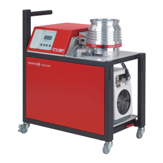
Product description 3 Product description 3.1 Function Turbopump stations are fully automatic pump units ready for connection. A turbo pumping station con- sists of a portable or mobile vacuum pump unit, with a turbopump and a specially matched backing pump. Fig. 2: Product overview with combination examples 1 Relay box Transport lock... -
Page 18: Drive
At excessively high temperatures, the electronic drive unit automatically reduces the drive power. 3.2 Identifying the product ► To ensure clear identification of the product when communicating with Pfeiffer Vacuum, always keep all of the information on the rating plate to hand. -
Page 19: Product Features
Product description 3.3 Product features HiPace 400 HiPace 300 HiPace 80 HiPace 700 Pascal 2021 Duo 20 ACP 28 Pascal 2010 ACP 15 Scroll 18 Duo 11 Scroll 12 Scroll 6 Fig. 5: Overview: Turbo and backing pump combinations Feature HiCube Pro Operating instruc- tions HV flange size... -
Page 20: Scope Of Delivery
Product description Feature HiCube Pro Operating instruc- tions Current supply with display DCU 110 DCU 310 DCU 400 DCU 400 PT 0250 BN and control unit Accessories Venting valve optional optional optional optional PT 0228 BN Housing heater (water cool- optional optional optional... -
Page 21: Transportation And Storage
Transportation and Storage 4 Transportation and Storage 4.1 Transporting the pumping station WARNING Danger of serious injury due to falling objects Due to falling objects there is a risk of injuries to limbs through to broken bones. ► Take particular care and pay special attention when transporting products manually. ►... -
Page 22: Transport Lock
Transportation and Storage Information for transport of the vacuum pump without packaging For transport without packaging, HiCube Pro turbopump stations are equipped with recesses on the side of the housing frame. 1. Remove the protective caps from the recesses. 2. Attach suitable lifting devices to at least 3 attachment points. 3. -
Page 23: Installation
Installation 5 Installation The installation of the turbopump and its fastening is of outstanding importance. The rotor of the turbo- pump revolves at very high speed. In practice it is not possible to exclude the risk of the rotor touching the stator (e.g. due to the penetration of foreign bodies into the high vacuum connection). The kinetic energy released acts on the housing and on the anchoring of the turbopump within fractions of a sec- ond. -
Page 24: Anchor Pumping Station
Installation 5.3 Anchor pumping station CAUTION Danger of injury due to the pumping station tipping or rolling away Superstructural parts change the center of gravity. There is a danger of crushing due to rolling away or tipping. ► Place the pumping station on a flat installation surface. ►... -
Page 25: Connecting The High Vacuum Side
5.4.2 Use splinter shield or protective screen Pfeiffer Vacuum centering rings with splinter shield or protective screen in the high vacuum flange pro- tect the turbopump against foreign matter from the vacuum chamber. The pumping speed of the turbo- pump reduces according to the passage guide values and the size of the high vacuum flange. -
Page 26: Using The Vibration Compensator
► Take suitable safety precautions on-site for the compensation of the occurring torques. ► Before installing a vibration compensator, you must first of all contact Pfeiffer Vacuum. Installing the vibration compensator 1. -
Page 27: Installation Of Iso-Kf Flange
Flange connection ISO-K to ISO-F, bracket screws Connection with bracket screw 1. For the connection of the turbopump, use only the approved mounting kits from Pfeiffer Vacuum. 2. Connect the flange with the components of the mounting kit according to the figure. - Page 28 ● Leak-tightness of the flange connection, however, is not jeopardized in this regard. Connection of claw and tapped hole 1. Only use the approved mounting kits from Pfeiffer Vacuum for the connection. 2. Connect the flange according to the diagram using the components in the mounting kit.
-
Page 29: Attaching Cf Flange To Cf-F
Connection of the hexagon head screw and through holes 1. For the connection of the turbopump, use only the approved mounting kits from Pfeiffer Vacuum. 2. If used: Insert the protective screen or splinter shield with clamping lugs downwards in the turbo- pump high vacuum flange. -
Page 30: Connect The Exhaust Side
Connection of the stud screw and tapped hole 1. For the connection of the turbopump, use only the approved mounting kits from Pfeiffer Vacuum. 2. Screw in the required number of stud screws with the shorter end in the holes on the counter flange. -
Page 31: Remove Transportation Lock
► Observe the permissible pressures and pressure differentials for the product. ► Check the function of the exhaust line on a regular basis. Condensate separator Pfeiffer Vacuum recommends installing a condensate separator, with condensate drain at the lowest point of the exhaust line. Fig. 13: Example backing pump exhaust connection 1 Exhaust connection, 1/2"... -
Page 32: Fill Operating Fluid
Product-specific performance data are not achieved. All liability and warranty claims against Pfeiffer Vacuum are also excluded. ► Only use approved operating fluids. ► Only use other application-specific operating fluids after consultation with Pfeiffer Vacuum. Use of operating fluids Only applies to HiCube Pro with rotary vane pump as backing pump. -
Page 33: Connecting Accessories
5. Screw in the filler screw again. – Be careful with the O-ring. 5.8 Connecting accessories Installation and operation of accessories Pfeiffer Vacuum offers a series of special, compatible accessories for its products. ● Information and ordering options for approved accessories for hybrid bearing turbo- pumps can be found online. -
Page 34: Tbl. 7: Pre-Set Accessory Connections To Electronic Drive Unit Tc 400
Electronic drive unit TC 110 accessory connection Connect accessory devices to the TC 110 ● The use of Pfeiffer Vacuum accessories via the TC 110 electronic drive unit is only possible using the corresponding connection cable and/or adapter on the X3 multi- functional connection. -
Page 35: Connecting Measuring Tubes
► Use the Y-connector from the accessories range if you want to connect 3 or 4 devices to the TC 400. 5.9 Connecting measuring tubes The connecting socket with designation "X3" is used to connect a Pfeiffer Vacuum transmitter. Measuring tubes Display on the DCU [P:738]... -
Page 36: Connect To The Mains Power Supply
Installation Procedure 1. Utilize the grounding cable on the inside of the electronics housing to discharge applicative inter- ferences. 2. Connect the eye for M4 grounding cable to a suitable connector. 3. Route the connection in accordance with locally applicable provisions. 5.11 Connect to the mains power supply WARNING Risk of fatal injury due to electric shock on account of incorrect installation... -
Page 37: Operation
Important settings and function-related variables are factory-programmed into the vacuum pumps elec- tronic drive units as parameters. Each parameter has a three-digit number and a description. Parame- ters can be used via Pfeiffer Vacuum DCU display and control units or externally via RS-485, using the Pfeiffer Vacuum protocol. -
Page 38: Switch On Turbo Pumping Station
Commission pumping station ► Switch on the turbo pumping station. 6.3 Normal operation Operating the DCU ► When working with the DCU 002 Pfeiffer Vacuum display and control unit, please see the associ- ated operating instructions supplied in the shipment. 38/80... -
Page 39: Stand-By Operation
Operation Parameter | use Description corresponds to Pumping station ON/OFF: All components are put [010] = 0 or 1 into/out of operation according to their configuration Error acknowledgement (Reset): Resets active malfunc- tion messages in case the cause is eliminated. [308] -->... -
Page 40: Eliminate Condensate Load
Operation NOTICE Risk of damage from condensation in vacuum pump Exceeding the saturation vapor pressure of process media during the compression phase leads to condensation in the suction chamber. This results in an increase of the achievable ultimate pressure and to a general deterioration of the performance data of the vacuum pump as a whole. Corrosion and contamination impair service life. -
Page 41: Operation Monitoring
Operation 6.7 Operation monitoring 6.7.1 Operating mode display via LED The LEDs on the front panel of the DCU display basic operating statuses. Symbol LED status Display Meaning without current On, flashing "Pumping station OFF", rotation speed ≤ 60 Green On, inverse flashing "Pumping station ON", set rotation speed not reached On, constant... -
Page 42: Venting
General information for fast venting We recommend fast venting of larger volumes in 4 steps. 1. Use a Pfeiffer Vacuum venting valve for the turbopump, or match the valve cross-section to the size of the recipient and maximum venting rate. -
Page 43: Maintenance
2. Clean the turbopump station exterior with a lint-free cloth and a little isopropanol. 3. Consult Pfeiffer Vacuum Service about shorter maintenance intervals for extreme loads or impure processes. 4. For all other cleaning, maintenance or repair work, contact the appropriate Pfeiffer Vacuum Serv- ice location. 43/80... -
Page 44: Removing Components For Maintenance
Maintenance 7.3 Removing components for maintenance NOTICE Malfunction due to changing the connection configuration The pumping station connections are pre-configured at the factory. If the control lines on the connec- tor are mixed up, this causes the pumping station to malfunction or fail. ►... -
Page 45: Fig. 20: Connections To The Turbo Pump
Maintenance Fig. 20: Connections to the turbo pump 1 Air cooling control cable ("accessory") RS-485 interface cable 2 Venting valve control cable ("accessory") Connection "DC in" 3 Fore-vacuum connection, clamping ring ACP or HiScroll backing pump control cable ("re- mote") Procedure 1. -
Page 46: Install Turbopump
Maintenance Required tools ● Allen key Procedure 1. Unscrew all fixing screws and washers from the mounting plate. 2. Lift the turbopump off the mounting plate. 3. Pay attention to the control cable. 4. Perform maintenance as specified in the operating instructions. Service turbopump The opening in the mounting plate makes it easy to perform maintenance work on the tur- bopump (e.g. -
Page 47: Fig. 22: Operating Fluid Change With Rotary Vane Pump As Backing Pump
Maintenance Required tools ● Allen key ● Calibrated torque wrench (tightening factor ≤ 1.6) Fig. 22: Operating fluid change with rotary vane pump as backing pump 1 Drain screw Filler screw 2 Sight glass Drain channel 3 Backing pump Draining the operating fluid 1. -
Page 48: Decommissioning
2. Clean the turbopump station exterior with a lint-free cloth and a little isopropanol. 3. If necessary, arrange for Pfeiffer Vacuum Service to fully clean the pumping station. 4. If necessary, arrange for Pfeiffer Vacuum Service to fully clean the pumping station components. 5. Install the pumping station according to these instructions (see chapter “Installation”, page... -
Page 49: Recycling And Disposal
6. Dispose of the product or components in a safe manner according to locally applicable regula- tions. 9.3 Dispose of rotary vane pump Pfeiffer Vacuum rotary vane pumps contain materials that you must recycle. 1. Fully drain the lubricant. 2. Dismantle the motor. -
Page 50: Dispose Of Multi-Stage Roots Pumps
6. Dispose of the product or components in a safe manner according to locally applicable regula- tions. 9.4 Dispose of multi-stage roots pumps Pfeiffer Vacuum roots pumps from the ACP series contain materials that you must recycle. 1. Fully drain the lubricant. 2. Decontaminate the components that come into contact with process gases. -
Page 51: Malfunctions
► Follow the installation instructions for this turbopump. ► Observe the requirements regarding stability and design of the counter flange. ► Use only original accessories or fixing material approved by Pfeiffer Vacuum for the installation. WARNING Risk of injury caused by the turbopump breaking away with the vibration compensator in the event of a malfunction Sudden jamming of the rotor generates high destructive torques in accordance with ISO 27892. -
Page 52: Error Codes
● Replace the pressure gauge com- pletely ** Error E040 ** Hardware error ● external RAM faulty ● Contact Pfeiffer Vacuum Service. ** Error E042 ** Hardware error ● EPROM checksum incorrect ● Contact Pfeiffer Vacuum Service. ** Error E043 ** Hardware error ●... - Page 53 Malfunctions Display Problem Possible causes Remedy E098 Internal communication er- ● Contact Pfeiffer Vacuum Service. E107 Final stage group error ● Contact Pfeiffer Vacuum Service. ● Acknowledge only at rotation speed f = 0 E108 Rotation speed measure- ● Contact Pfeiffer Vacuum Service.
- Page 54 Malfunctions Display Problem Possible causes Remedy F116 Bearing temperature evalu- ● Contact Pfeiffer Vacuum Service. ation faulty F117 Pump lower part high tem- ● Faulty cooling ● Improve the cooling perature ● Check the operating conditions F118 Final stage high tempera- ●...
-
Page 55: Service Solutions By Pfeiffer Vacuum
We are always focused on perfecting our core competence – servicing of vacuum components. Once you have purchased a product from Pfeiffer Vacuum, our service is far from over. This is often exactly where service begins. Obviously, in proven Pfeiffer Vacuum quality. - Page 56 Service solutions by Pfeiffer Vacuum 5. Prepare the product for transport in accordance with the provisions in the contamination declaration. a) Neutralize the product with nitrogen or dry air. b) Seal all openings with blind flanges, so that they are airtight.
-
Page 57: Accessories
Accessories 12 Accessories We recommend Please refer to the accessories list for the individual components in their respective operat- ing instructions or online at Accessories portfolio for hybrid bearing turbopumps. 57/80... -
Page 58: Technical Data And Dimensions
Technical data and dimensions 13 Technical data and dimensions 13.1 General This section describes the basis for the technical data of Pfeiffer Vacuum turbopumps. Technical data Maximum values refer exclusively to the input as a single load. ● Specifications according to PNEUROP committee PN5 ●... -
Page 59: Tbl. 21: Technical Data Hicube 80 Pro, Dn 40 Iso-Kf
Technical data and dimensions Type desig- HiCube 80 HiCube 80 HiCube 80 HiCube 80 HiCube 80 nation Backing ACP 15 ACP 28 HiScroll 6 HiScroll 12 HiScroll 18 pump Final pres- < 1 · 10 < 1 · 10 1 · 10 1 ·... - Page 60 Technical data and dimensions Type designation HiCube 80 Pro HiCube 80 Pro HiCube 80 Pro HiCube 80 Pro Cooling method, standard Relative humidity 5 – 85 %, non- 5 – 85 %, non- 5 – 85 %, non- 5 – 85 %, non- of air condensing condensing...
-
Page 61: Tbl. 24: Technical Data Hicube 80 Pro, Dn 63 Iso-K
Technical data and dimensions Type designation HiCube 80 Pro HiCube 80 Pro HiCube 80 Pro HiCube 80 Pro Final pressure < 1 · 10 < 1 · 10 < 1 · 10 < 1 · 10 without gas ballast Pumping speed for 67 l/s 67 l/s 67 l/s... -
Page 62: 2Technical Data Hicube 300 Pro
Technical data and dimensions Type desig- HiCube 80 HiCube 80 HiCube 80 HiCube 80 HiCube 80 nation Shipping and -10 – 55 °C -10 – 55 °C -10 – 50 °C -10 – 50 °C -10 – 50 °C storage tem- perature Weight 66 kg... -
Page 63: Tbl. 27: Technical Data Hicube 300 Pro, Dn 100 Iso-K
Technical data and dimensions Type des- HiCube 300 HiCube 300 HiCube 300 HiCube 300 HiCube 300 ignation Pumping 260 l/s 260 l/s 260 l/s 260 l/s 260 l/s speed for Pumping 14 m³/h 27 m³/h 6.1 m³/h 12.1 m³/h 18.1 m³/h speed backing pump at 50... - Page 64 Technical data and dimensions Type designa- HiCube 300 Pro HiCube 300 Pro HiCube 300 Pro HiCube 300 Pro tion Sound pressure ≤50 dB(A) ≤50 dB(A) ≤50 dB(A) ≤50 dB(A) level Cooling method, standard Relative humidity 5 – 85 %, non- 5 –...
-
Page 65: 3Technical Data Hicube 300 H Pro
Technical data and dimensions Type designation HiCube 300 Pro HiCube 300 Pro HiCube 300 Pro HiCube 300 Pro Connection flange DN 100 CF-F DN 100 CF-F DN 100 CF-F DN 100 CF-F (in) Connection flange G 1/2 G 1/2 G 1/2 G 1/2 (out) Turbopump... - Page 66 Technical data and dimensions Type des- HiCube 300 H HiCube 300 H HiCube 300 H HiCube 300 H HiCube 300 H ignation Input volt- ±10 % ±10 % ±10 % ±10 % ±10 % age: toler- ance Motor for Asia, Europe Asia, Europe Asia, Europe Asia, Europe...
-
Page 67: Tbl. 32: Technical Data Hicube 300 H Pro, Dn 100 Iso-K
Technical data and dimensions Type designa- HiCube 300 H HiCube 300 H HiCube 300 H HiCube 300 H tion Shipping and -20 – 55 °C -20 – 55 °C -20 – 55 °C -20 – 55 °C storage tempera- ture Weight 71.5 kg 96.5 kg... -
Page 68: 4Technical Data Hicube 400 Pro
Technical data and dimensions Type designation HiCube 300 H HiCube 300 H HiCube 300 H HiCube 300 H Final pressure < 5 · 10 < 5 · 10 < 5 · 10 < 5 · 10 without gas ballast Pumping speed 260 l/s 260 l/s 260 l/s... -
Page 69: Tbl. 35: Technical Data Hicube 400 Pro, Dn 100 Iso-K
Technical data and dimensions Type des- HiCube 400 HiCube 400 HiCube 400 HiCube 400 HiCube 400 ignation Power con- 910 W 1160 W 940 W 1420 W 1900 W sumption max. Sound ≤50 dB(A) ≤50 dB(A) ≤50 dB(A) ≤50 dB(A) ≤50 dB(A) pressure level... - Page 70 Technical data and dimensions Type desig- HiCube 400 HiCube 400 HiCube 400 HiCube 400 HiCube 400 nation Connection DN 100 CF-F DN 100 CF-F DN 100 CF-F DN 100 CF-F DN 100 CF-F flange (in) Connection G 1/2 G 1/2 G 1/2 G 1/2 G 1/2...
-
Page 71: 5Technical Data Hicube 700 Pro
Technical data and dimensions Type designation HiCube 400 Pro HiCube 400 Pro HiCube 400 Pro HiCube 400 Pro Motor for region Asia, Europe Asia, Europe Asia, Europe Asia, Europe Power consump- 750 W 1350 W 1000 W 1000 W tion max. Sound pressure ≤50 dB(A) ≤50 dB(A) - Page 72 Technical data and dimensions Type des- HiCube 700 HiCube 700 HiCube 700 HiCube 700 HiCube 700 ignation Shipping -10 – 55 °C -10 – 55 °C -10 – 50 °C -10 – 50 °C -10 – 50 °C and storage tempera- ture Weight...
-
Page 73: Tbl. 41: Technical Data Hicube 700 Pro, Dn 160 Cf-F
Technical data and dimensions Type desig- HiCube 700 HiCube 700 HiCube 700 HiCube 700 HiCube 700 nation Pumping 14 m³/h 27 m³/h 6.1 m³/h 12.1 m³/h 18.1 m³/h speed back- ing pump at 50 Hz Input volt- 200 – 230 V 200 –... -
Page 74: 6Technical Data Hicube 700 H Pro
Technical data and dimensions Type designation HiCube 700 Pro HiCube 700 Pro HiCube 700 Pro HiCube 700 Pro Shipping and stor- -20 – 55 °C -20 – 55 °C -20 – 55 °C -20 – 55 °C age temperature Weight 77 kg 102 kg 84 kg... -
Page 75: Tbl. 44: Technical Data Hicube 700 H Pro, Dn 160 Iso-K
Technical data and dimensions Type designa- HiCube 700 H HiCube 700 H HiCube 700 H HiCube 700 H tion Connection DN 160 ISO-K DN 160 ISO-K DN 160 ISO-K DN 160 ISO-K flange (in) Connection G 1/2" G 1/2" G 1/2" G 1/2"... -
Page 76: Dimension Drawings
Technical data and dimensions Type desig- HiCube 700 H HiCube 700 H HiCube 700 H HiCube 700 H HiCube 700 H nation Motor for re- Asia, Europe Asia, Europe Asia, Europe Asia, Europe Asia, Europe gion Power con- 910 W 1160 W 940 W 1420 W... -
Page 77: Tbl. 47: Dimensions Hicube 80 Pro
Technical data and dimensions Fig. 23: Dimensions HiCube Pro Dimensions HiCube 80 Pro HiCube 80 Pro HiCube 80 Pro Flange DN 40 ISO-KF DN 63 ISO-K DN 63 CF-F 680 mm 671 mm 676 mm 158 mm 149 mm 155 mm Tbl. -
Page 78: Declaration Of Conformity
DIN EN 61000-6-4: 2011 DIN EN IEC 63000: 2019 DIN EN 61010-1: 2011 The authorized representative for the compilation of technical documents is Mr. Tobias Stoll, Pfeiffer Vacuum GmbH, Berliner Straße 43, 35614 Asslar, Germany. Signature: Pfeiffer Vacuum GmbH Berliner Straße 43... - Page 79 79/80...
Need help?
Do you have a question about the HICUBE PRO Series and is the answer not in the manual?
Questions and answers