Table of Contents
Advertisement
Quick Links
Advertisement
Table of Contents

Related Manuals for Pfeiffer Vacuum HIPACE 80 NEO


Summary of Contents for Pfeiffer Vacuum HIPACE 80 NEO
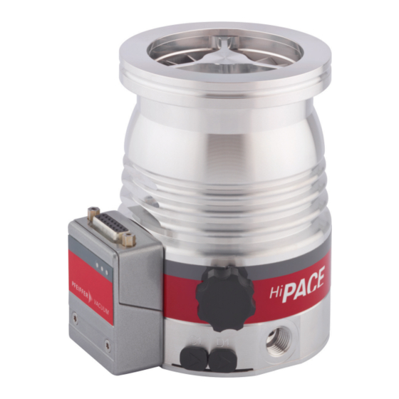
- Page 1 OPERATING INSTRUCTIONS Translation of the Original HIPACE 80 NEO Turbopump...
- Page 2 Dear Customer, Thank you for choosing a Pfeiffer Vacuum product. Your new turbopump is designed to support you by its performance, its perfect operation and without interfering your individual application. The name Pfeiffer Vacuum stands for high-quality vacuum technology, a comprehensive and complete range of top-quality products and first-class service.
-
Page 3: Table Of Contents
Limits of use of the product Proper use Foreseeable improper use Personnel qualification 2.7.1 Ensuring personnel qualification 2.7.2 Personnel qualification for maintenance and repair 2.7.3 Advanced training with Pfeiffer Vacuum Product description Function 3.1.1 Cooling 3.1.2 Rotor bearing 3.1.3 Drive Identifying the product 3.2.1 Product types... - Page 4 Table of contents Commissioning Operating modes 6.2.1 Operation without operating unit 6.2.2 Operation via multi-function connection "X3" 6.2.3 Operation via Pfeiffer Vacuum display and control unit Switching on the turbopump Operation monitoring 6.4.1 Operating mode display via LED 6.4.2 Temperature monitoring Switching off and venting 6.5.1 Switching off...
- Page 5 Tbl. 16: Conversion table: Pressure units Tbl. 17: Conversion table: Units for gas throughput Tbl. 18: Technical data for HiPace 80 Neo, other connection flanges for the output are optional Tbl. 19: Materials that make contact with the process media 5/58...
- Page 6 Electronic drive unit installation and removal Fig. 17: Spare parts, HiPace 80 Neo Fig. 18: HiPace 80 Neo | DN 40 ISO-KF Fig. 19: HiPace 80 Neo | DN 63 ISO-K Fig. 20: HiPace 80 Neo | DN 63 CF-F...
-
Page 7: About This Manual
Keep the manual for future consultation. 1.1 Validity This operating instructions is a customer document of Pfeiffer Vacuum. The operating instructions de- scribe the functions of the named product and provide the most important information for the safe use of the device. The description is written in accordance with the valid directives. The information in this op- erating instructions refers to the product's current development status. -
Page 8: Pictographs
Rating plate The rating plate of the turbopump is located on the lower part D-35614 Asslar of the vacuum pump. HiPace 80 Neo Mod. PM P080 _ _ _ _ _ Rating plate of the electronic drive unit - - - - - - - -... -
Page 9: Abbreviations
Flange: Metal-sealed connector in accordance with ISO 3669 Diameter value (in mm) Direct current Display Control Unit (Pfeiffer Vacuum display and control unit). Nominal diameter as size description Rotation speed value of a vacuum pump (frequency, in rpm or Hz) Handheld Programming Unit. -
Page 10: Safety
Safety 2 Safety 2.1 General safety information The following 4 risk levels and 1 information level are taken into account in this document. DANGER Immediately pending danger Indicates an immediately pending danger that will result in death or serious injury if not observed. ►... - Page 11 ► Take suitable safety precautions on-site for the compensation of the occurring torques. ► Before installing a vibration compensator, you must first of all contact Pfeiffer Vacuum. WARNING Danger to life from poisoning where toxic process media leak from damaged connections Sudden twisting of the turbopump in the event of a fault causes fittings to accelerate.
- Page 12 ► Install suitable touch protection if the vacuum pump is accessible to untrained persons. ► Allow the vacuum pump to cool down before carrying out any work. ► Contact Pfeiffer Vacuum for suitable touch protection in system solutions. Risks during operation...
- Page 13 ► Install suitable touch protection if the vacuum pump is accessible to untrained persons. ► Allow the vacuum pump to cool down before carrying out any work. ► Contact Pfeiffer Vacuum for suitable touch protection in system solutions. Risks during maintenance, decommissioning and disposal...
-
Page 14: Safety Precautions
► Follow the installation instructions for this turbopump. ► Observe the requirements regarding stability and design of the counter flange. ► Use only original accessories or fixing material approved by Pfeiffer Vacuum for the installation. WARNING Risk of injury caused by the turbopump breaking away with the vibration compensator in the event of a malfunction Sudden jamming of the rotor generates high destructive torques in accordance with ISO 27892. -
Page 15: Limits Of Use Of The Product
Safety Infringement of conformity due to modifications to the product The Declaration of Conformity from the manufacturer is no longer valid if the operator changes the original product or installs additional equipment. ● Following the installation into a system, the operator is required to check and re-evalu- ate the conformity of the overall system in the context of the relevant European Direc- tives, before commissioning that system. -
Page 16: Proper Use
The work described in this document may only be carried out by persons who have appropriate profes- sional qualifications and the necessary experience or who have completed the necessary training as provided by Pfeiffer Vacuum. Training people 1. Train the technical personnel on the product. -
Page 17: Ensuring Personnel Qualification
─ Customer with Pfeiffer Vacuum service training ─ Pfeiffer Vacuum service technician 2.7.3 Advanced training with Pfeiffer Vacuum For optimal and trouble-free use of this product, Pfeiffer Vacuum offers a comprehensive range of courses and technical trainings. For more information, please contact Pfeiffer Vacuum technical training. -
Page 18: Product Description
3 Product description 3.1 Function The turbopump forms a compact unit with the electronic drive unit. Pfeiffer Vacuum power supply packs provide the voltage supply. Integrated temperature monitoring for the rotor reduces the power consump- tion of the turbopump if the rotor temperature exceeds the limit value. In addition to the multi-function connection of the electronic drive unit, the turbopump has two micro-USB sockets for connecting Pfeiff- er Vacuum accessories directly. -
Page 19: Drive
ID no. 000021320. 3.2.1 Product types The product designation of Pfeiffer Vacuum turbopumps from the HiPace series is composed of the family name, the size (which is based on the pumping speed of the vacuum pump) and, if required, an additional feature description. -
Page 20: Transportation And Storage
► Do not stack the products. ► Wear protective equipment, e.g. safety shoes. We recommend Pfeiffer Vacuum recommends keeping the transport packaging and original protective cov- Instructions for safe transport ► Transport the turbopump only within the permissible temperature limits. -
Page 21: Installation
► Install suitable touch protection if the vacuum pump is accessible to untrained persons. ► Allow the vacuum pump to cool down before carrying out any work. ► Contact Pfeiffer Vacuum for suitable touch protection in system solutions. General notes for the installation of vacuum components ►... -
Page 22: Connecting The High Vacuum Side
Requirements for the dimensioning of high vacuum connection supplied by the cus- tomer Important information for correct installation ► Only use the approved mounting kits of Pfeiffer Vacuum for the high vacuum connection of the turbopump. 5.2.2 Consider earthquake protection NOTICE... -
Page 23: Using A Splinter Shield Or Protective Screen
Safety connections, customer-side 5.2.3 Using a splinter shield or protective screen Pfeiffer Vacuum centering rings with splinter shield or protective screen in the high vacuum flange pro- tect the turbopump against foreign matter from the vacuum chamber. The pumping speed of the turbo- pump reduces according to the passage guide values and the size of the high vacuum flange. -
Page 24: Mounting Orientations
4. Observe the fastening of the ISO flanges. 5.2.5 Mounting orientations Pfeiffer Vacuum turbopumps of the HiPace Neo series are suitable for use with dry compressing back- ing pumps for mounting in all orientations. ► When using oil-sealed backing pumps, avoid backflow from the fore-vacuum range. -
Page 25: Attaching Iso-K Flange Onto Iso-K
Flange connection ISO-K to ISO-F, bracket screws Connection with bracket screw 1. For the connection of the turbopump, use only the approved mounting kits from Pfeiffer Vacuum. 2. Connect the flange with the components of the mounting kit according to the figure. -
Page 26: Attaching Cf Flange To Cf-F
Installation Connection of hexagon head set screw and tapped hole 1. Only use the approved mounting kits from Pfeiffer Vacuum for the connection. 2. Place the collar flange over the high vacuum flange on the turbopump. 3. Insert the snap ring into the side groove on the high vacuum flange of the turbopump. -
Page 27: Fig. 7: Flange Connection Cf-F, Hexagon Head Screw And Through Hole
Connection of the hexagon head screw and through holes 1. For the connection of the turbopump, use only the approved mounting kits from Pfeiffer Vacuum. 2. If used: Insert the protective screen or splinter shield with clamping lugs downwards in the turbo- pump high vacuum flange. -
Page 28: Connecting Fore-Vacuum Side
Connection of the stud screw and through hole 1. For the connection of the turbopump, use only the approved mounting kits from Pfeiffer Vacuum. 2. If used: Insert the protective screen or splinter shield with clamping lugs downwards in the turbo- pump high vacuum flange. -
Page 29: Connecting Accessories
Connect accessory devices to the TC 80 ● Use of Pfeiffer Vacuum accessories via the electronic drive unit TC 80 is enabled via a corresponding connection cable or adapter at the “X3” multi-function connection. ● The desired accessory output is configured via RS-485 using Pfeiffer Vacuum display and control units or a PC. -
Page 30: Connecting The Electrical Supply
► Observe the installation instructions in the operating instructions for the relevant accessory. ► Note the existing configuration of existing connections and control lines. ► Use a Pfeiffer Vacuum display and control unit with an integrated power supply pack. 5.5 Connecting the electrical supply... -
Page 31: Fig. 13: Connecting Electronic Drive Unit To Power Supply Pack
Installation WARNING Danger of cut injuries from unexpected start up. The use of mating plugs of the electronic drive unit (accessories) enables the automatic run-up of the vacuum pump as soon the power is turned on. Attaching mating plugs before or during the installa- tion leads to the movement of parts hence the risk of cut injuries by sharp-edged in the exposed high vacuum flange. -
Page 32: Operation
Simultaneous loading by means of high drive power (gas throughput, fore-vacuum pressure), high heat radiation, or strong magnetic fields results in uncontrolled heating of the rotor and can destroy the vacuum pump. ► Consult Pfeiffer Vacuum before combining varying loads on the vacuum pump. Lower limit val- ues apply. NOTICE... -
Page 33: Operating Modes
"with bridges" and running the supply voltage. Notes on operation without control unit 1. Only use the approved Pfeiffer Vacuum connection cables with bridges on the "X3" connection on the electronic drive unit. -
Page 34: Switching On The Turbopump
6.4.1 Operating mode display via LED LEDs on the electronic drive unit show the basic operating states of the vacuum pump. A differentiated error and warning display is only possible for operation with the Pfeiffer Vacuum display and control unit or a PC. -
Page 35: Temperature Monitoring
Operation Symbol LED status Display Meaning No error, no warning On, constant Error, malfunction Tbl. 9: Behavior and meaning of the LEDs on the electronic drive unit 6.4.2 Temperature monitoring If threshold values are exceeded, output signals from temperature sensors bring the turbopump to a safe condition. -
Page 36: Venting
General information for fast venting We recommend fast venting of larger volumes in 4 steps. 1. Use a Pfeiffer Vacuum venting valve for the turbopump, or match the valve cross-section to the size of the recipient and maximum venting rate. -
Page 37: Maintenance
Maintenance Level 2 and Level 3 We recommend Pfeiffer Vacuum Service (PV) carry out maintenance work at Level 2 and Level 3 (inspection). If the specified intervals are exceeded, or if maintenance work is car- ried out improperly, no warranty or liability claims are accepted on the part of Pfeiffer Vac- uum. -
Page 38: Replace Operating Fluid Reservoir
Maintenance ► Pay attention to when the operating fluid must be changed. ► For any questions relating to maintenance, contact the appropriate Pfeiffer Vacuum Service loca- tion. Action Inspection Mainte- Mainte- Mainte- Required ma- nance lev- nance lev- nance lev-... -
Page 39: Remove Operating Fluid Reservoir
● When ordering spare parts, make sure you use the correct pump article number and the operating fluid reservoir. ● This information can be found on the pump rating plate. You can find the safety data sheet in the Pfeiffer Vacuum Download Center. Prerequisites ● Turbopump off ●... -
Page 40: Assemble Operating Fluid Reservoir
Maintenance Remove operating fluid reservoir 1. Wear laboratory gloves to avoid skin contact. 2. Place the turbopump on the closed high vacuum flange. 3. Unscrew the Torx screws from the closing cap. 4. Lift the closing cap off the pump bottom part. 5. -
Page 41: Replace Electronic Drive Unit
Maintenance 7.4 Replace electronic drive unit NOTICE Damage to the turbopump and electronic drive unit due to improper disconnection of compo- nents Even after the mains power is switched off, the turbopump continues to deliver electrical energy dur- ing its run-down period. If the turbopump and electronic drive unit are disconnected prematurely, there is the risk of a short-circuit to ground and consequently the destruction of electronic compo- nents. -
Page 42: Confirming Speed Specification
5. Set the parameter [P:777] to the required value of the nominal rotation speed in Hertz. Alternative to adjusting the nominal rotation speed confirmation A Pfeiffer Vacuum SpeedConfigurator for the one-time immediate setting of parameter [P:777] is included with the replacement units. -
Page 43: Decommissioning
2. Clean the turbopump exterior with a lint-free cloth and a little isopropanol. 3. If necessary, arrange for Pfeiffer Vacuum Service to completely clean the turbopump. 4. Observe the total running time of the turbopump and if necessary, arrange for Pfeiffer Vac- uum Service to replace the bearing. -
Page 44: Recycling And Disposal
9.1 General disposal information Pfeiffer Vacuum products contain materials that you must recycle. ► Dispose of our products according to the following: – Iron –... -
Page 45: Malfunctions
► Follow the installation instructions for this turbopump. ► Observe the requirements regarding stability and design of the counter flange. ► Use only original accessories or fixing material approved by Pfeiffer Vacuum for the installation. WARNING Risk of injury caused by the turbopump breaking away with the vibration compensator in the event of a malfunction Sudden jamming of the rotor generates high destructive torques in accordance with ISO 27892. -
Page 46: Tbl. 13: Troubleshooting Turbopumps
● Reduce the process gas load. ● Rotor not running ● Check the turbopump for noise development smoothly, defective ● Contact Pfeiffer Vacuum Service. bearing ● Run-up time setpoint ● Extend the run-up time setpoint [P:700] via a dis- adjusted too low play and control unit. -
Page 47: Service Solutions By Pfeiffer Vacuum
We are always focused on perfecting our core competence – servicing of vacuum components. Once you have purchased a product from Pfeiffer Vacuum, our service is far from over. This is often exactly where service begins. Obviously, in proven Pfeiffer Vacuum quality. - Page 48 Service solutions by Pfeiffer Vacuum 5. Prepare the product for transport in accordance with the provisions in the contamination declaration. a) Neutralize the product with nitrogen or dry air. b) Seal all openings with blind flanges, so that they are airtight.
-
Page 49: Spare Parts, Hipace 80 Neo
Spare parts, HiPace 80 Neo 12 Spare parts, HiPace 80 Neo Fig. 17: Spare parts, HiPace 80 Neo Position Designation Order number Remark Pieces Electronic drive unit TC 80 refer to the rating plate Operating fluid reservoir refer to the rating plate incl. -
Page 50: Accessories
Optionally with splinter shield or protective screen. Power supply packs and display units Power supply packs for optimal voltage supply of Pfeiffer Vacuum products are characterized by their compact size and adapted power supply with maximum reliability. Display and operating units are used to check and adjust operating parameters. -
Page 51: Tbl. 15: Accessories
TCS 13, adapter for TC 110/120 with interface RS-485, 2 accessory ports and cou- PM 061 856 -U pling set Air cooling, shielded, for HiPace 80 Neo | HiPace 30 Neo PM Z01 367 Extension cable M8 on M8 PM 061 783 -T Venting valve, shielded, 24 V DC, G 1/8", for connection to TC 110/120... -
Page 52: Technical Data And Dimensions
Technical data and dimensions 14 Technical data and dimensions 14.1 General This section describes the basis for the technical data of Pfeiffer Vacuum turbopumps. Technical data Maximum values refer exclusively to the input as a single load. ● Specifications according to PNEUROP committee PN5 ●... - Page 53 Technical data and dimensions Type designation extended HiPace® 80 Neo HiPace® 80 Neo HiPace® 80 Neo with TC 80 with TC 80 with TC 80 Pumping speed for Ar 30 l/s 66 l/s 66 l/s Pumping speed for H 38 l/s 48 l/s 48 l/s Pumping speed for He...
-
Page 54: Substances In Contact With The Media
Weight 1.7 kg 1.7 kg 3.1 kg Tbl. 18: Technical data for HiPace 80 Neo, other connection flanges for the output are option- 14.3 Substances in contact with the media Substances in contact with the media Aluminum alloy Stainless steel Rare-earth magnets... -
Page 55: Fig. 18: Hipace 80 Neo | Dn 40 Iso-Kf
Technical data and dimensions DN 40 ISO-KF 67 .4 DN 16 ISO-KF (G1/4”) Fig. 18: HiPace 80 Neo | DN 40 ISO-KF DN 63 ISO-K DN 16 ISO-KF 67.4 (G1/4”) Fig. 19: HiPace 80 Neo | DN 63 ISO-K DN 63 CF-F 67.4... -
Page 56: Declaration Of Conformity
DIN EN 61010-1: 2011 DIN EN 61326-1: 2013 DIN EN 62061: 2013 The authorized representative for the compilation of technical documents is Mr. Tobias Stoll, Pfeiffer Vacuum GmbH, Berliner Straße 43, 35614 Asslar, Germany. Signature: Pfeiffer Vacuum GmbH Berliner Straße 43... - Page 57 57/58...
Need help?
Do you have a question about the HIPACE 80 NEO and is the answer not in the manual?
Questions and answers