
Related Manuals for Pfeiffer Vacuum HiCube 30 Eco


Summary of Contents for Pfeiffer Vacuum HiCube 30 Eco
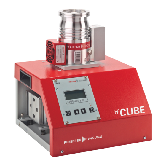
- Page 1 OPERATING INSTRUCTIONS Translation of the Original HICUBE ECO Turbo pumping stations...
- Page 2 Dear Customer, Thank you for choosing a Pfeiffer Vacuum product. Your new turbo pumping station is designed to support you by its performance, its perfect operation and without interfering your individual application. The name Pfeiffer Vacuum stands for high-quality vacuum technology, a comprehensive and complete range of top-quality products and first-class service.
-
Page 3: Table Of Contents
Table of contents Table of contents About this manual Validity 1.1.1 Applicable documents 1.1.2 Variants Target group Conventions 1.3.1 Instructions in the text 1.3.2 Pictographs 1.3.3 Stickers on the product 1.3.4 Abbreviations Safety General safety instructions Safety instructions Safety precautions Limits of use of the product Proper use Foreseeable improper use... - Page 4 7.4.2 Dismantling the turbopump from the pumping station Decommissioning Shutting down for longer periods Recommissioning Disposing of the vacuum pump Malfunctions General Troubleshooting Error codes Service solutions from Pfeiffer Vacuum Accessories Technical data and dimensions 12.1 General 12.2 Technical data 12.3 Dimensioned drawings Declaration of Conformity 4/60...
- Page 5 Tbl. 18: Technical data HiCube 30 Eco, DN 40 ISO-KF............51 Tbl. 19: Technical data HiCube 30 Eco, DN 63 CF-F............51 Tbl. 20: Technical data HiCube 30 Eco, DN 63 ISO-K............52 Tbl. 21: Technical data HiCube 80 Eco, DN 40 ISO-KF............52 Tbl.
- Page 6 Fig. 20: Electrical connections....................39 Fig. 21: Dismantling the turbopump..................39 Fig. 22: Dimensions of HiCube 30 Eco, DN 40 ISO-KF............55 Fig. 23: Dimensions of HiCube 30 Eco, DN 63 CF-F............56 Fig. 24: Dimensions of HiCube 30 Eco, DN 63 ISO-K............56 Fig.
-
Page 7: About This Manual
Keep the manual for future consultation. 1.1 Validity These operating instructions are for customers of Pfeiffer Vacuum. They describe the function of the designated product and provide the most important information for safe usage of the product. The de- scriptions comply with applicable directives. All information provided in these operating instructions refer to the current development status of the product. -
Page 8: Pictographs
About this manual 1.3.2 Pictographs Pictographs used in the document indicate useful information. Note 1.3.3 Stickers on the product This section describes all the stickers on the product along with their meaning. Rating plate The rating plate is located on the back of the pumping station D-35614 Asslar HiCube 80 Eco Mod. -
Page 9: Abbreviations
Metal-sealed connector conforming to ISO 3669 Measurement of the diameter (in mm) Display Control Unit (display and control unit from Pfeiffer Vacuum). Nominal diameter as size description Measurement of the rotation speed of a vacuum pump (frequency, in rpm or Hz) -
Page 10: Safety
Safety 2 Safety 2.1 General safety instructions This document includes the following four risk levels and one information level. DANGER Imminent danger Indicates a hazardous situation which, if not avoided, will result in death or serious injury. ► Instructions on avoiding the hazardous situation WARNING Possibly imminent danger Indicates a hazardous situation which, if not avoided, could result in death or serious injury. - Page 11 ► Take suitable safety precautions on-site for the compensation of the occurring torques. ► Before installing a vibration compensator, you must first of all contact Pfeiffer Vacuum. CAUTION Risk of injury from bursting due to high pressure in the exhaust line Faulty or insufficient exhaust lines cause hazardous situations, e.g.
- Page 12 There is a risk of serious injury, potentially even fatal, and significant equip- ment damage. ► Follow the installation instructions for this turbopump. ► Observe the requirements regarding stability and design of the counter flange. ► Use only original accessories or fixing material approved by Pfeiffer Vacuum for the installation. 12/60...
-
Page 13: Safety Precautions
► Take suitable safety precautions on-site for the compensation of the occurring torques. ► Before installing a vibration compensator, you must first of all contact Pfeiffer Vacuum. 2.3 Safety precautions Duty to provide information on potential dangers The product holder or user is obliged to make all operating personnel aware of dan- gers posed by this product. -
Page 14: Proper Use
Safety Parameter Limit value Degree of contamination Ambient temperature 5°C to 35°C with air cooling 5°C to 40°C with water cooling Permissible surrounding magnetic field depending on turbopump used Maximum irradiated thermal output depending on turbopump used Maximum permissible rotor temperature of the turbopump 90 °C Tbl. -
Page 15: Product Description
3 Product description 3.1 Identifying the product ► To ensure clear identification of the product when communicating with Pfeiffer Vacuum, always keep all of the information on the rating plate to hand. ► Learn about certifications through test seals on the product or at www.tuvdotcom.com... -
Page 16: Scope Of Delivery
Product description Tbl. 4: Pumping station component combination options 3.2 Scope of delivery ● HiCube Eco turbo pumping station ● Protective cover for the high vacuum flange ● Extension cable M12 on M12, 3 m ● Power supply cable, country-specific ● Operating instructions for the turbo pumping station and individual components 3.3 Function Turbo pumping stations are fully automatic pump units ready for connection. -
Page 17: Drive
Product description Fig. 4: DCU control panel LC display, illuminated LED operating display Status icons Control keys 3.3.2 Drive ● Electronic drive unit of the turbopump ● Electronic drive unit of the backing pump 3.3.3 Cooling ● Air cooling ● Water cooling (optional) At excessively high temperatures, the electronic drive unit automatically reduces the drive power. -
Page 18: Transportation And Storage
Transportation and Storage 4 Transportation and Storage 4.1 Transporting the pumping station WARNING Danger of serious injury due to falling objects Due to falling objects there is a risk of injuries to limbs through to broken bones. ► Take particular care and pay special attention when transporting products manually. ►... -
Page 19: Storing The Pumping Station
Transportation and Storage 4.3 Storing the pumping station Packing We recommend storing the product in its original packaging. 1. Close all flange openings with the original protective caps. 2. Close all other connections (e.g. exhaust) with the corresponding protective caps. 3. Only store the turbo pumping station within the specified limits. 4. -
Page 20: Installation
Installation 5 Installation The installation of the turbopump and its fastening is of outstanding importance. The rotor of the turbo- pump revolves at very high speed. In practice it is not possible to exclude the risk of the rotor touching the stator (e.g. due to the penetration of foreign bodies into the high vacuum connection). The kinetic energy released acts on the housing and on the anchoring of the turbopump within fractions of a sec- ond. -
Page 21: Connecting The High Vacuum Side
The total weight of superstructural parts must not exceed the maximum values specified. If the rotor is suddenly blocked, the torques arising from the system and the high vacuum flange must be absorbed. The installation elements for turbo pumps are special designs by Pfeiffer Vacuum. 21/60... -
Page 22: Using Accessories For The High Vacuum Connection
270 N/mm Tbl. 5: Requirements for on-site high vacuum connection ► Only use the approved mounting kits of Pfeiffer Vacuum for the high vacuum connection of the turbopump. 5.4.2 Using accessories for the high vacuum connection Installation and operation of accessories Pfeiffer Vacuum offers a series of special, compatible accessories for its products. -
Page 23: Connecting The Turbopump Externally
1. Follow the installation instructions for the turbopump in the associated operating instructions for the individual components. 2. Use cable kit PM 071 477 -T (3 m) from the Pfeiffer Vacuum accessories range. – Other lengths available on request. 3. Extend the fore-vacuum line and the control cable. -
Page 24: Attaching Iso-K Flange Onto Iso-K
Flange connection ISO-K to ISO-F, bracket screws Connection with bracket screw 1. For the connection of the turbopump, use only the approved mounting kits from Pfeiffer Vacuum. 2. Connect the flange with the components of the mounting kit according to the figure. - Page 25 Installation Connection of hexagon head set screw and tapped hole 1. Only use the approved mounting kits from Pfeiffer Vacuum for the connection. 2. Place the collar flange over the high vacuum flange on the turbopump. 3. Insert the snap ring into the side groove on the high vacuum flange of the turbopump.
-
Page 26: Fastening Cf Flange To Cf-F
Connection of the hexagon head screw and through holes 1. For the connection of the turbopump, use only the approved mounting kits from Pfeiffer Vacuum. 2. If used: Insert the protective screen or splinter shield with clamping lugs downwards in the turbo- pump high vacuum flange. -
Page 27: Connecting The Exhaust Side
Connection of the stud screw and through hole 1. For the connection of the turbopump, use only the approved mounting kits from Pfeiffer Vacuum. 2. If used: Insert the protective screen or splinter shield with clamping lugs downwards in the turbo- pump high vacuum flange. -
Page 28: Modifying The Dcu For Remote Operation
2. Safely store the attachment nipple. 3. Remove DCU from pumping station housing. – Note control cable length. 4. Unscrew M12 control cable connecting plug from DCU. Cable included in shipment Other cable lengths are available on request from the Pfeiffer Vacuum accessories. 28/60... -
Page 29: Connecting Accessories For The Pumping Station
● The following accessories are not included in the scope of supply. Accessory connection for TC 110 electronic drive unit ● The use of Pfeiffer Vacuum accessories via the TC 110 electronic drive unit is only possible using the corresponding connection cable and/or adapter on the X3 multi-functional connection. -
Page 30: Grounding The Pumping Station
Installation Fig. 15: Backing pump transport lock Transport lock hexagon nut Required tool ● Hexagonal wrench (13 WAF) Procedure 1. Rotate the transport lock hexagon nut upwards to the stop. 2. Also release the transport lock on the opposite side. 5.9 Grounding the pumping station Fig. -
Page 31: Fig. 17: Power Supply Connector And Master Switch On Hicube Eco
Installation WARNING Danger to life from electric shock in the event of a fault In the event of a fault, devices connected to the mains may be live. There is a danger to life from electric shock when making contact with live components. ►... -
Page 32: Operation
Important settings and function-related variables are factory-programmed into the vacuum pumps elec- tronic drive units as parameters. Each parameter has a three-digit number and a description. Parame- ters can be used via Pfeiffer Vacuum display and control panels or externally via RS-485, using the Pfeiffer Vacuum protocol. -
Page 33: Switching On The Turbo Pumping Station
► Switch on the turbo pumping station. 6.3 Normal operation Operating the DCU ► When working with the DCU 002 Pfeiffer Vacuum display and control unit, please see the associ- ated operating instructions supplied in the shipment. Parameter | use Description... -
Page 34: Fig. 18: Example: Dcu Display For Second Parameter Set
Operation ● The MVP 015-4 and MVP 030-3 backing pumps have a sufficiently high water vapor tolerance, and are not equipped with gas ballast valve. ● The MVP 015-2 backing pump is equipped with an electronic gas ballast valve. ● The parameters for automatic gas ballast valve operation of the are factory-set for normal applica- tion. -
Page 35: Operation Monitoring
Operation Switch on the turbo pumping station. 6.5 Operation monitoring 6.5.1 Operating mode display via LED The LEDs on the front panel of the DCU display basic operating statuses. Symbol LED status Display Meaning without current On, flashing "Pumping station OFF", rotation speed ≤ 60 rpm Green On, inverse flashing "Pumping station ON", set rotation speed not reached... -
Page 36: Venting
General information for fast venting We recommend fast venting of larger volumes in 4 steps. 1. Use a Pfeiffer Vacuum venting valve for the turbopump, or match the valve cross-section to the size of the recipient and maximum venting rate. -
Page 37: Maintenance
2. Clean the turbopump station exterior with a lint-free cloth and a little isopropanol. 3. Consult Pfeiffer Vacuum Service about shorter maintenance intervals for extreme loads or impure processes. 4. For all other cleaning, maintenance or repair work, contact the appropriate Pfeiffer Vacuum Serv- ice location. 7.3 Replacing mains fuses... -
Page 38: Removing Components For Maintenance
Maintenance Fig. 19: Replace main fuses Master switch Fuses Fuse holder Mains plug Replacing faulty fuses Spare parts required ● 2 x fuses, 5 x 20 (T 2 A H 250 V AC) 1. Shut down the pumping station. 2. Disconnect mains cable from the mains plug. 3. -
Page 39: Removing The Electrical Connections
Maintenance 7.4.1 Removing the electrical connections Before carrying out any work, safely disconnect device from mains 1. Shut down the device. 2. Wait until all components are at a complete standstill. 3. Switch off the master switch. 4. Disconnect the mains cable from the device. Fig. - Page 40 Maintenance Required tools ● Allen key ● Calibrated torque wrench (tightening factor ≤ 1.6) Procedure 1. Loosen and remove the fore-vacuum line from the turbopump. 2. Make sure not to kink or damage the fore-vacuum hose. 3. Unscrew all 4 fixing screws and washers from the mounting plate. –...
-
Page 41: Decommissioning
2. Clean the turbopump station exterior with a lint-free cloth and a little isopropanol. 3. If necessary, arrange for Pfeiffer Vacuum Service to fully clean the pumping station. 4. If necessary, arrange for Pfeiffer Vacuum Service to fully clean the pumping station components. 5. Install the pumping station according to these instructions (see chapter “Installation”, page... -
Page 42: Malfunctions
► Follow the installation instructions for this turbopump. ► Observe the requirements regarding stability and design of the counter flange. ► Use only original accessories or fixing material approved by Pfeiffer Vacuum for the installation. WARNING Risk of injury caused by the turbopump breaking away with the vibration compensator in the event of a malfunction Sudden jamming of the rotor generates high destructive torques in accordance with ISO 27892. -
Page 43: Error Codes
● Replace the pressure gauge com- pletely ● external RAM faulty ● Contact Pfeiffer Vacuum Service. ** Error E040 ** Hardware error ● EPROM checksum incorrect ● Contact Pfeiffer Vacuum Service. ** Error E042 **... - Page 44 ● Connection to the pump ● Check connections unit - pump faulty faulty ● Acknowledge only at rotation speed f = 0 ● Contact Pfeiffer Vacuum Service. E010 Internal device error ● Acknowledge only at rotation speed f = 0 E021 Electronic drive unit does ●...
- Page 45 F003 TMS heating circuit temper- ● TMS temperature not in ● Check the operating conditions ature sensor the permissible range ● Contact Pfeiffer Vacuum Service. between +5 °C and 85 °C ● Mains failure ● Check the mains supply F007 Undervoltage/power failure ●...
-
Page 46: Tbl. 15: Error And Warning Messages For Mvp 015 Diaphragm Pump Electronic Drive Unit
Possible causes Remedy E117 Excess temperature pump ● Faulty cooling ● Improve the cooling ● Check the operating conditions ● Contact Pfeiffer Vacuum Service. E173 Pump overflow E174 Pump blocked ● Contact Pfeiffer Vacuum Service. Tbl. 15: Error and warning messages for MVP 015 diaphragm pump electronic drive unit... -
Page 47: Service Solutions From Pfeiffer Vacuum
We are consistently striving to perfect our core competence, service for vacuum components. And our service is far from over once you’ve purchased a product from Pfeiffer Vacuum. It often enough really just begins then. In proven Pfeiffer Vacuum quality, of course. - Page 48 ERKLÄRUNG KONTAMINIERUNG Then send your product to your local Service Center. You will receive a confirmation message/a quotation from Pfeiffer Vacuum. For all service orders, our General Terms and Conditions of Sales and Supply General Terms and Conditions of Repair and Maintenance apply to vacuum equipment and components.
-
Page 49: Accessories
Accessories 11 Accessories We recommend Please refer to the accessories list for the individual components in their respective operating instructions or online at pfeiffer-vacuum.de. 49/60... -
Page 50: Technical Data And Dimensions
Technical data and dimensions 12 Technical data and dimensions 12.1 General This section describes the basis for the technical data of Pfeiffer Vacuum turbopumps. Technical data Maximum values refer exclusively to the input as a single load. ● Specifications according to PNEUROP committee PN5 ●... - Page 51 5 – 85 %, not condens- 5 – 85 %, not condens- Weight 11.7 kg 13.4 kg 13.3 kg Tbl. 18: Technical data HiCube 30 Eco, DN 40 ISO-KF Classification HiCube 30 Eco HiCube 30 Eco HiCube 30 Eco Flange (in) DN 63 CF-F...
- Page 52 5 – 85 %, not condens- 5 – 85 %, not condens- Weight 11.7 kg 13.4 kg 13.3 kg Tbl. 20: Technical data HiCube 30 Eco, DN 63 ISO-K Classification HiCube 80 Eco HiCube 80 Eco HiCube 80 Eco Flange (in) DN 40 ISO-KF...
- Page 53 Technical data and dimensions Ultimate pressure < 1 · 10 < 1 · 10 < 1 · 10 Pumping speed for N 67 l/s 67 l/s 67 l/s Pumping speed backing pump at 50 Hz 1 m³/h 0.75 m³/h 1.8 m³/h Pump-down time for vacuum chamber 56 s 83 s...
- Page 54 Technical data and dimensions Backing pump MVP 015-2 MVP 015-4 MVP 030-3 MVP 015-2 MVP 015-4 MVP 030-3 Ultimate pressure < 1 · 10 < 1 · 10 < 1 · 10 < 1 · 10 < 1 · 10 <...
-
Page 55: Dimensioned Drawings
15.9 kg 17.6 kg 17.5 kg 15.9 kg 17.6 kg 17.5 kg Tbl. 25: Technical data HiCube 300 Eco, DN 100 ISO-K 12.3 Dimensioned drawings All dimensions given in mm Fig. 22: Dimensions of HiCube 30 Eco, DN 40 ISO-KF 55/60... -
Page 56: Fig. 23: Dimensions Of Hicube 30 Eco, Dn 63 Cf-F
Technical data and dimensions Fig. 23: Dimensions of HiCube 30 Eco, DN 63 CF-F Fig. 24: Dimensions of HiCube 30 Eco, DN 63 ISO-K Fig. 25: Dimensions of HiCube 80 Eco, DN 40 ISO-KF Fig. 26: Dimensions of HiCube 80 Eco, DN 63 CF-F... -
Page 57: Fig. 27: Dimensions Of Hicube 80 Eco, Dn 63 Iso-K
Technical data and dimensions Fig. 27: Dimensions of HiCube 80 Eco, DN 63 ISO-K Fig. 28: Dimensions of HiCube 300 Eco, DN 100 CF-F Fig. 29: Dimensions of HiCube 300 Eco, DN 100 ISO-K 57/60... -
Page 58: Declaration Of Conformity
DIN EN ISO 12100:2011 DIN EN 1012-2:2011 DIN EN 61000-3-2:2014 DIN EN 61000-3-3:2014 DIN EN 61010-1:2010 DIN EN 61326-1:2013 DIN EN 62061:2013 Signature: Pfeiffer Vacuum GmbH Berliner Straße 43 35614 Asslar Germany (Dr. Ulrich von Hülsen) Asslar, 2016-09-10 Managing director... - Page 59 59/60...
Need help?
Do you have a question about the HiCube 30 Eco and is the answer not in the manual?
Questions and answers