Canon EOS C300 Mark II Instruction Manual
Digital cinema camera
Hide thumbs
Also See for EOS C300 Mark II:
- Instruction manual (223 pages) ,
- Read this first manual (42 pages) ,
- Manual (25 pages)

Related Manuals for Canon EOS C300 Mark II


Summary of Contents for Canon EOS C300 Mark II
- Page 1 PUB. DIE-0549-000G Digital Cinema Camera Firmware ver. 1.0.7.1 ( ver. 1.0.9.1 ( Instruction Manual...
-
Page 2: Safety Instructions
Safety Instructions Be sure to read these instructions in order to operate the product safely. Follow these instructions to prevent injury or harm to the operator of the product or others. WARNING Denotes the risk of serious injury or death. •... - Page 3 This product is not to be disposed of with your household waste. This product should be handed over to a designated collection point. For more information regarding return and recycling of WEEE products, please visit https://in.canon/en/consumer/web/e-waste or write to us at cipl.ewaste@canon.co.in Also, this product including its components, consumables, parts and spares complies with the “E-Waste (Management) Rules, 2022”...
-
Page 5: Table Of Contents
Table of Contents Safety Instructions 2 Preparing Recording Media 43 Compatible Recording Media 43 1. Introduction 9 Inserting a CFexpress Card 44 About this Manual 9 Removing a CFexpress Card 44 Conventions Used in this Manual 9 Inserting and Removing an SD Card 45 Supplied Accessories 10 Initializing Recording Media 46 Before Using the Camera 11... - Page 6 Image Stabilization 91 Recorded 113 Zoom 92 Using Metadata 114 Onscreen Markers, Zebra Patterns and False Setting a User Memo Created with Canon XF Color 93 Utility 114 Displaying Onscreen Markers 93 Entering Slate Information About the Displaying Zebra Patterns 95...
- Page 7 4. Customization 125 Connecting to an External Monitor or Recorder 152 Assignable Buttons 125 Using the SDI OUT Terminal 152 Custom Picture Settings 129 Using the MON. Terminal 153 Selecting Custom Picture Files 129 Using the HDMI OUT Terminal 153 Preset Picture Settings 129 Enabling simultaneous output from the MON.
- Page 8 FTP File Transfer 180 Transferring a Single Clip 180 Transferring All Clips 180 IP Streaming 181 Browser Remote: Controlling the Camera from a Network Device 183 Starting Browser Remote 183 Using Browser Remote 185 Recording remotely using an XC Protocol compatible controller/application 190 Recording remotely using the RC-IP100/ RC-IP1000 Remote Camera Controller 190...
-
Page 9: Introduction
About this Manual Thank you for purchasing the Canon EOS C300 Mark III / EOS C500 Mark II. Please read this manual carefully before you use the camera and retain it for future reference. Should the camera fail to operate correctly, refer to Troubleshooting (A 217). -
Page 10: Supplied Accessories
Supplied Accessories Supplied Accessories The following accessories are supplied with the camera. LM-V2 LCD Monitor LA-V2 LCD Attachment Unit Handle Unit GR-V1 Camera Grip* (incl. grip attachment ring) Microphone Holder BP-A60 Battery Pack CG-A20 Battery Charger CA-CP200 B Compact Power Adapter (incl. -
Page 11: Before Using The Camera
Supplied Accessories Before Using the Camera • Before making important recordings for the first time, make test recordings using the video configuration(s) you plan to use to check that the camera operates correctly. Should it fail to operate correctly, refer to Troubleshooting (A 217). -
Page 12: Names Of Parts
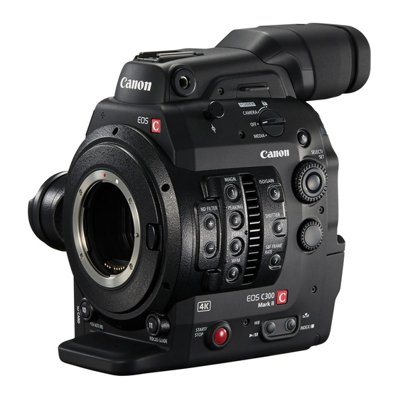
Names of Parts Names of Parts Camera 14 15 9 Q switch 1 Tape measure hook and focal plane mark 2 MAGN. (magnification) button (A 84)/ Set to CAMERA to turn on the camera or to OFF Assignable button Camera 1* to turn it off. - Page 13 Names of Parts (illumination) button 7 Air intake vent (A 61) Turns on/off the illumination of the buttons on the 8 Card compartment cover (A 44, 45) camera’s left and back sides. This is convenient 9 CFexpress card release buttons: for CFexpress for night time or black-out operation.
- Page 14 Names of Parts 1 USB terminal 8 Camera grip attachment thread/Rosette (A 41) For connecting the optional GP-E2 GPS Receiver. Compliant with ARRI rosettes. 2 Exhaust ventilation outlet (A 61) 9 GRIP (camera grip connection) terminal (A 41) 3 Audio level switches for CH1 (top) and CH2 10 Audio level dials for CH1 (top) and CH2 (bottom) (bottom) (A 107) (A 107)
- Page 15 Names of Parts EF lens mount 1 Front tally lamp (A 51) 6 EF lens mount index (A 37) 2 VIDEO terminal (A 29) 7 Lens release button (A 37) 3 Lens mount fixation bolts 8 EF lens lock pin 4 PUSH AUTO IRIS (momentary automatic aperture) 9 ONE-SHOT AF (focus automatically once) button button (A 76)/...
- Page 16 Names of Parts 1 Expansion unit connector 12 TIME CODE terminal (A 99, 100) For connecting the optional EVF-V50 OLED 13 REMOTE A terminal (A 122) Electronic Viewfinder or expansion units. For connecting the optional RC-V100 Remote 2 Expansion unit connector cover Controller or commercially available remote 3 Power indicator/Rear tally lamp (A 51) controllers.
- Page 17 Names of Parts 1 Tape measure hook 11 Sockets for tripod’s anti-rotation pin Use the hook to accurately measure the distance (5 mm (0.20 in.) deep, x2) from the focal plane. For tripods with 1/4"-20 mounting screws. 2 Screw holes for 1/4"-20 mounting screws 12 M4 screws for expansion unit connector cover (9 mm (0.35 in.) deep, x6) 13 Strap mounts...
-
Page 18: Lm-V2 Lcd Monitor
Names of Parts LM-V2 LCD Monitor 1 LCD panel with touch screen (A 29, 31) 6 CANCEL button (A 34) 2 FUNC (main functions) button (A 68)/ 7 DISP (display) button (A 53, 57)/ Assignable button LCD LM-V1/V2 1 (A 125) Assignable button LCD LM-V1/V2 2 (A 125) 8 LCD monitor’s position alignment mark Í... -
Page 19: La-V2 Lcd Attachment Unit
Names of Parts LA-V2 LCD Attachment Unit (A 29) 1 LCD monitor fixation bolt 7 Pivot B 2 Base 1 8 Base 2 3 Sockets for the microphone holder (A 42) 9 Locking knob 4 Cable clamp 10 LCD monitor mount 11 LCD monitor’s position alignment mark Í... -
Page 20: Gr-V1 Camera Grip
Names of Parts GR-V1 Camera Grip (A 41) At the time of purchase, the camera grip is pre-attached to the camera. 1 Control dial (A 72, 75) 4 Joystick (A 34) 2 REC (start/stop recording) button (A 51) 5 FOCUS GUIDE button (A 83)/ 3 Grip belt Assignable button Camera Grip 1 (A 125) Adjust the grip belt so that you can reach the REC... -
Page 21: Handle Unit
Names of Parts Handle Unit (A 29) 1 Screw holes for 1/4"-20 screws 5 Rear accessory mount with socket for 1/4"-20 (6 mm (0.24 in.) deep, x4) screws (8.8 mm (0.35 in.) deep) 2 Front accessory mount with socket for 1/4"-20 6 Locking knob screws (8.8 mm (0.35 in.) deep) 7 Rear mounting hole (through-hole) -
Page 22: 4K And Higher Resolutions: Workflow Overview
4K and Higher Resolutions: Workflow Overview 4K and Higher Resolutions: Workflow Overview The following illustrates the typical workflow for 5.9K/4K recording with the camera. 5.9K recording is available only with the EOS C500 Mark II model. Recording Post-production 4K recording Full-quality SDI OUT / data... -
Page 23: Color Grading With The Aces Workflow
Input Transform: Refers to the table used for converting color information of the input device to ST2065-1 color space. It can be downloaded from Canon’s website. Output Transform: Refers to the table used for mapping ST2065-1 color space information to the specific color - 0.2... - Page 24 4K and Higher Resolutions: Workflow Overview...
-
Page 25: Preparations
Preparations Preparing the Power Supply You can power the camera using a battery pack or the DC IN 12V terminal. Even when a battery pack is attached, if a power source is connected to the DC IN 12V terminal, the camera will not draw power from the battery pack. - Page 26 Preparing the Power Supply NOTES • We recommend charging the battery pack in temperatures between 10 ºC and 30 ºC (50 ºF and 86 ºF). Outside the temperature range of 0 ºC to 40 ºC (32 ºF to 104 ºF), charging will not start. •...
-
Page 27: Using The Dc In 12V Terminal
Preparing the Power Supply Checking the Remaining Battery Charge You can check the approximate charge level on the battery pack itself. The remaining battery charge level displayed on the recording/playback screen may not match the level shown on the status screen or the indicators on the battery pack. - Page 28 Preparing the Power Supply NOTES • If the power supplied to the camera is at or below the level set for the power level warning (A 205), the camera will not start recording. If the power supply’s voltage falls below the level necessary to operate the camera while recording, recording will stop and the camera will turn off.
-
Page 29: Preparing The Handle Unit And Lcd Monitor
(A 40) and to the Cinema EOS System Expansion User Guide (PDF file), available for download from your local Canon website. Attaching the Handle Unit 1 Slide the mounting base at the bottom of the handle unit into the camera’s top accessory shoe and gently push it all the way... - Page 30 Preparing the Handle Unit and LCD Monitor 6 Connect the LCD monitor to the camera’s VIDEO terminal using the supplied UN-5 Unit Cable. • Align the Í marks on the cable’s plugs and terminals. 7 Put the cable through the LCD attachment unit’s cable clamp.
-
Page 31: Adjusting The Lcd Monitor
Preparing the Handle Unit and LCD Monitor 7 Connect the LCD monitor to the camera’s VIDEO terminal using the supplied UN-5 Unit Cable. • Align the Í marks on the cable’s plugs and terminals. • If necessary, adjust the position of the cable so that it does not get in the picture or obstruct the view. -
Page 32: Removing The Lcd Monitor And Lcd Attachment Unit
Preparing the Handle Unit and LCD Monitor NOTES • Based on the LCD monitor’s position, you can invert the image displayed on the screen. Repeatedly pressing the MIRROR button will change the displayed image in the following order: Image inverted horizontally Image inverted vertically ... -
Page 33: Date, Time And Language Settings
Date, Time and Language Settings Date, Time and Language Settings Setting the Date and Time You will need to set the date and time on the camera before you can start using it. The [Date/Time] screen will appear automatically when the camera’s clock is not set. 1 Select the desired time zone and move to the next field. -
Page 34: Using The Menus
Using the Menus Using the Menus Many of the camera’s functions can be adjusted from the menu that opens after pressing the MENU button. In CAMERA mode, you can also register frequently used menu settings in a customized menu (My Menu) for easy Menu Options access. -
Page 35: Using The Customized Menus (My Menu)
Using the Menus 3 Press SET (press the SET button or press the joystick itself). • You can also push the joystick down to move the cursor to the list of menu items. 4 Select the desired menu item ([Language ], in the example) and then press SET. - Page 36 Using the Menus Rearranging Menu Settings 1 Select > [¥ My Menu] > [Edit] > [Move]. 2 Select the menu setting you want to move. • The ] icon will appear next to the setting you selected to move. 3 Move the menu setting to the desired position and press SET. Removing Menu Settings 1 Select >...
-
Page 37: Preparing The Lens
Preparing the Lens Preparing the Lens As much as possible, attach and remove the lens quickly and in a clean environment free of dust. Refer also to the instruction manual of the lens used. IMPORTANT • When attaching/removing a lens, avoid direct sunlight or strong light sources. Also, be careful not to drop the camera or lens. -
Page 38: Updating The Firmware Of An Ef Lens
You can update the lens firmware of the EF lens attached to the camera. For details about firmware updates for EF lenses, visit your local Canon website. 1 Download the lens firmware update file from the Canon website and save it on an SD card. Insert the SD card containing the lens firmware update into the camera (A 45). -
Page 39: In-Camera Lens Correction
• If correction data is not available, [Periph. Illum. Corr.] or [Chromatic Aberr. Corr.] will appear grayed out. Visit your local Canon website and check if there is correction data available for the lens you are using. If so, download the necessary update package, update the camera’s firmware version and repeat the procedure from the beginning. -
Page 40: Preparing Other Accessories
Your camera is incredibly versatile and allows you to build the shooting configuration that best fits your needs and shooting conditions. In addition to the supplied accessories, Canon offers a variety of optional accessories that expand the functionality of the camera (A 233). For details about accessories compatible with this camera, please download the Cinema EOS System Expansion User Guide (PDF file), available from your local Canon website. -
Page 41: Removing And Attaching The Camera Grip
Preparing Other Accessories Removing and Attaching the Camera Grip The camera grip comes originally attached to the camera. You can remove it and replace it with the thumb rest when a minimal configuration is necessary. Removing the Camera Grip 1 Turn off the camera. 2 Unscrew the camera grip’s locking screw and gently detach the grip. -
Page 42: Attaching The Microphone Holder
Preparing Other Accessories Attaching the Microphone Holder 1 Attach the microphone holder to the LCD attachment unit. 2 Use a commercially available Phillips head (“crosshead”) screwdriver to secure it firmly with the supplied M4 bolts. -
Page 43: Preparing Recording Media
CFexpress cards compliant with CFexpress 2.0 Type B specifications. However, it may not be possible to record on the card depending on the camera mode and bit rate used. For details about CFexpress cards tested for use with this camera, visit your local Canon website. SD cards... -
Page 44: Inserting A Cfexpress Card
Preparing Recording Media Inserting a CFexpress Card 1 Slide the card compartment cover switch all the way in the direction of the arrow. • The card compartment cover will open to the left. 2 Insert the card straight, with the label facing the back of the camera (the side with the battery compartment) all the way into one of the CFexpress card slots. -
Page 45: Inserting And Removing An Sd Card
Preparing Recording Media Inserting and Removing an SD Card 1 Wait until the SD CARD access indicator is off or is illuminated in green. 2 Slide the card compartment cover switch all the way in the direction of the arrow. •... -
Page 46: Initializing Recording Media
Preparing Recording Media Initializing Recording Media Initialize cards when you use them with this camera for the first time. You can also initialize a card to permanently delete all the recordings it contains. 1 Select > [Æ Recording/Media Setup] > [Initialize Media]. 2 Select [CFexpress A], [CFexpress B] or [SD Card]. -
Page 47: Relay Recording And Double Slot Recording
Preparing Recording Media Relay Recording and Double Slot Recording In CAMERA mode, the camera features two convenient recording methods that can be used when both CFexpress card slots contain a card: relay recording and double slot recording. Relay Recording This function allows you to continue recording on the other card without interruption when the card you are using becomes full. -
Page 48: Recovering Clips
Preparing Recording Media Recovering Clips Some actions, such as suddenly turning off the camera or removing the card while data is being recorded, can cause data errors in the recorded clip. In MEDIA mode, you may be able to recover clips with corrupted data using the following procedure. -
Page 49: Adjusting The Black Balance
Adjusting the Black Balance Adjusting the Black Balance In CAMERA mode, you can have the camera adjust the black balance automatically when ambient temperature changes considerably or if there is a noticeable change in a true black video signal. 1 Attach the body cap to the lens mount and set the camera to CAMERA mode. •... - Page 50 Adjusting the Black Balance...
-
Page 51: Recording
Recording Recording Video and Photos Recording This section explains the basics of recording clips* and photos. For details on recording audio, refer to Audio (A 102). * “Clip” refers to a single movie unit recorded with a single recording operation. You can also include metadata with the clip. Recording Power indicator/ rear tally lamp... - Page 52 • 8 appears at the top right of the screen and the photo is recorded on the SD card. • The SD CARD access indicator will illuminate in red. IMPORTANT • Be sure to save your recordings regularly, especially after making important recordings. Canon shall not be liable for any loss or corruption of data. NOTES NOTES •...
-
Page 53: Onscreen Displays
Recording Video and Photos Onscreen Displays Refer to this section for an explanation of the various screen displays that appear in CAMERA mode. You can use the custom display function ( 199) to turn off individual onscreen displays if they are not required. The menu item that controls each display is given in the following tables (1: indicates a menu item under [Custom Display 1] and 2: indicates a menu item under [Custom Display 2]). - Page 54 Recording Video and Photos Left side of the screen Icon/Display Description Custom Display 0000 mm Approximate focal length of the lens. 1: [Focal Length] Focus mode (A 81). 1: [Focus Mode] Face AF (A 89). Digital tele-converter (A 92) 1: [Tele-converter] Image stabilization (A 91).
- Page 55 Recording Video and Photos Icon/Display Description Custom Display Double slot recording (A 47). 2: [Recording Mode] Recording operation Ü STBY, Clip recording: record standby, recording. S&F STBY, Slow & fast motion recording (A 117): record standby, recording. Ü S&F PRE STBY, Pre-recording (A 119): record standby, recording.
- Page 56 Recording Video and Photos Icon/Display Description Custom Display MON. terminal disabled / HDMI OUT terminal active (A 152). 2: [Output Terminals Status] (in red) Output onscreen displays (A 154). 2: [OSD Output] ^ (in yellow) Magnification (A 84). 1: [Magnification] J, K (in yellow) Peaking (A 84).
-
Page 57: Selecting The Onscreen Display Level
Recording Video and Photos Selecting the Onscreen Display Level You can press the DISP button to change the onscreen display level and control the amount of information shown over the image. In CAMERA mode, you can customize each display level individually. Press the DISP button to select the desired display level. - Page 58 Recording Video and Photos Peripheral Border Display You can apply the peripheral border display to all display levels in CAMERA mode. With the peripheral border display, the camera’s image is reduced slightly so the onscreen displays are shown mostly around it and not on top of it, partially hiding it.
-
Page 59: Setting A Card's Volume Label
Options [Canon]: The volume label of CFexpress and SDXC cards will be “CANON” regardless of the clip file name settings. [Canon + Metadata]: The volume label of CFexpress and SDXC cards will be “CANONX999” where “X” represents the camera index and “999”... - Page 60 1 Select > [Æ Recording/Media Setup] > [Metadata] > [User Defined] > [Change]. • To reset the user-defined field to [CANON], select [Reset] instead. 2 Enter the desired text string using the data entry screen (A 60). To set the file naming method for proxy clips Select the string to be added automatically to the end of the file name for proxy clips.
-
Page 61: Using The Fan
Recording Video and Photos Using the Fan The camera uses a cooling fan to lower the camera’s internal temperature. In CAMERA mode, you can change the fan’s operation mode and speed. In MEDIA mode, the fan runs at all times but you can select its speed. Setting the Fan’s Operation in CAMERA Mode 1 Select >... -
Page 62: Video Configuration: Video Format, Sensor Mode
Video Configuration: Video Format, Sensor Mode, System Frequency, Resolution and Frame Rate Video Configuration: Video Format, Sensor Mode, System Frequency, Resolution and Frame Rate In CAMERA mode, you can set the video configuration used for primary clips with the following procedures. Select the video format, sensor mode, resolution (frame size), system frequency and frame rate settings that best match your creative needs. -
Page 63: Selecting The Frame Rate
Video Configuration: Video Format, Sensor Mode, System Frequency, Resolution and Frame Rate Selecting the Frame Rate When shooting RAW clips, the frame rate will determine also the color depth. Refer to the following tables. This procedure is not necessary when the system frequency is set to 24.00 Hz. 1 Select >... - Page 64 Video Configuration: Video Format, Sensor Mode, System Frequency, Resolution and Frame Rate System frequency/Frame rate Sensor mode Resolution Color depth Bit rate* 50.00 Hz 24.00 Hz 50.00P 25.00P 24.00P Ü 10 bit – – Super 35mm 4096x2160 1 Gbps Super 35mm Ü...
- Page 65 Video Configuration: Video Format, Sensor Mode, System Frequency, Resolution and Frame Rate System frequency/Frame rate Sensor mode Resolution/Color sampling Bit rate* 50.00 Hz 24.00 Hz 50.00P 50.00i 25.00P 24.00P 810 Mbps, Ü – – – Intra-frame 410 Mbps, Ü Ü –...
-
Page 66: Proxy Clips (Simultaneous Recording)
BT.709 Normal BT.709 Standard BT.709 Standard BT.709 Standard BT.709 Wide DR BT.709 Wide DR BT.709 Wide DR Canon 709 Canon 709 Canon 709 Gamma curve of BT.709 The gamma curve and color space after Custom Picture applying the Look File and after conversion are [SDR BT.709] or [SDR... - Page 67 Proxy Clips (Simultaneous Recording) • If there is no CFexpress card inserted in the camera, only the proxy clip will be recorded. • SDHC cards are formatted using the FAT32 file system so, when recording proxy clips, the video (stream) file in the clip will be split approximately every 4 GB.
-
Page 68: Direct Setting Mode (Func Button)
Direct Setting Mode (FUNC Button) Direct Setting Mode (FUNC Button) In CAMERA mode, you can adjust main camera functions—shutter speed, ISO speed/gain, aperture and white balance—using the FUNC button (direct setting mode). This section will explain the basic operation of the direct setting mode. -
Page 69: Shutter Speed
Shutter Speed Shutter Speed In CAMERA mode, you can set the shutter speed according to the shooting conditions. For example, you may want to set slower shutter speeds in darker environments. The camera offers the following modes. You can also perform this function remotely using Browser Remote on a connected network device (A 183, 186). -
Page 70: Changing The Shutter Speed Mode And Value
Shutter Speed Changing the Shutter Speed Mode and Value 1 Select > [ Camera Setup] > [Shutter Mode] > Desired shutter speed mode. 2 For [Speed] only: Select > [ Camera Setup] > [Shutter Increment] > [1/3 stop] or [1/4 stop]. 3 Adjust the shutter speed, angle value or clear scan frequency using the direct setting mode (A 68). -
Page 71: Iso Speed/Gain
The minimum sensitivity needed to obtain the recommended dynamic range depends on the gamma curve component of the [Gamma/Color Space] setting in the custom picture file (A 133). [Canon Log 2], [Canon Log 3], or [PQ]: ISO 800 / 12 dB gain [HLG] or [BT.709 Wide DR]: ISO 400 / 6 dB gain [BT.709 Normal] or [BT.709 Standard]: ISO 160 / –2 dB gain... -
Page 72: Changing The Iso Speed Or Gain Value
ISO Speed/Gain Changing the ISO Speed or Gain Value 1 Select > [ Camera Setup] > [ISO/Gain] > [ISO] or [Gain]. 2 Depending on your previous selection, select > [ Camera Setup] > [ISO Increment] (ISO speed) or [Gain Increment] (gain). 3 Select the desired option. -
Page 73: Nd Filter
ND Filter ND Filter In CAMERA mode, using the ND filter allows you to open up the aperture to obtain a shallower depth of field even when recording in bright surroundings. You can also use the ND filter to avoid the soft focus caused by diffraction when using small apertures. -
Page 74: Aperture
Aperture Aperture In CAMERA mode, you can affect the brightness of your recordings or change the depth of field by adjusting the aperture. Depending on the lens used, the aperture value displayed may differ (F value or T value) and available aperture values will vary as well. -
Page 75: Using The Control Dial
Aperture Using the Control Dial You can also adjust the lens’s aperture value using the control dial on the camera or the one on the camera grip. By default, the function of both control dials is set to [Iris]. You can select the function assigned to each control dial independently. -
Page 76: Momentary Automatic Aperture - Push Auto Iris
Aperture Momentary Automatic Aperture - Push Auto Iris During manual aperture, you can press the PUSH AUTO IRIS button to have the camera temporarily take control and adjust the aperture automatically for an optimal exposure. This function is not available when slow & fast motion recording is activated. 1 Select >... -
Page 77: Exposure Compensation - Ae Shift
Aperture Exposure Compensation - AE Shift Use AE shift to compensate the exposure that was set using automatic aperture, in order to darken or lighten the image. You can also perform this function remotely using Browser Remote on a connected network device (A 183, 186). -
Page 78: White Balance
White Balance White Balance In CAMERA mode, the camera uses an electronic white balance process to calibrate the picture and produce accurate colors under different lighting conditions. The camera offers the following ways to set the white balance. You can also perform this function remotely using Browser Remote on a connected network device (A 183, 186). -
Page 79: Color Temperature/Preset White Balance
White Balance Å 4 Press the button. • The Å A or Å B icon will flash quickly. • Make sure the gray card or white object fills the screen until the procedure is completed. • Once the icon stops flashing, the procedure is completed. The setting is retained even if you turn off the camera. -
Page 80: Auto White Balance (Awb)
White Balance Auto White Balance (AWB) The camera constantly adjusts the white balance automatically to achieve an appropriate level. The camera will adjust the white balance if the light source changes. 1 Press the WB button. • The camera will enter the direct setting mode (A 68) with the white balance mode icon highlighted. -
Page 81: Focus
Focus Focus In CAMERA mode, the camera offers the following ways to focus, depending on the lens used. The camera incorporates Dual Pixel CMOS AF technology for advanced autofocus performance with compatible lenses. Refer to the list of compatible lenses and functions that can be used (A 242). You can also adjust the focus remotely using Browser Remote on a connected network device (A 183, 185). -
Page 82: Manual Focus
Focus Required settings on EF Cinema lenses and broadcast lenses To adjust the focus from the camera, you will need to change the focus mode using the controls on the lens. Required settings vary depending on the lens. Refer to the following table and the instruction manual of the lens used. - Page 83 Focus Focus guide The focus guide gives you an intuitive visual indication of the current focus distance and the direction and amount of adjustment necessary to bring the selected subject into full focus. When used in combination with face detection (A 89), the guide will focus on the vicinity of the eyes of the person detected as the main subject.
- Page 84 Focus Peaking The camera offers two peaking levels. 1 Press the PEAKING button. • The peaking icon (J or K) appears on the left of the screen and outlines (contour lines) in the image that are in focus will be shown highlighted. •...
- Page 85 Focus Focus Position Guide When a compatible lens (A 242) is attached, you will be able to display the current focus position and the preregistered focus positions. Depending on the lens, you may need to connect a 12-pin interface cable to the LENS terminal of an optional EU-V2 Expansion Unit 2 or EU-V3 Expansion Unit 3.
-
Page 86: One-Shot Af
Focus One-Shot AF In this focus mode, you will focus manually in most situations but still have the option to have the camera focus automatically only once on the subject inside the AF frame. You can change the size and position of the AF frame. -
Page 87: Continuous Af
- With some EF lenses, the camera may take longer to focus automatically or may not be able to focus correctly. Visit your local Canon website for the latest information. • You can change the adjustment speed and responsiveness of the autofocus function with the following settings. -
Page 88: Changing The Af Frame Size And Position
Focus AF Lock While using continuous AF or AF-Boosted MF, you can lock the focus on a certain subject and then move the camera to change the composition. To use AF lock, you must set an assignable button to [AF Lock] in advance. 1 Set an assignable button to [AF Lock] (A 125). -
Page 89: Face Detection
Focus Face Detection When the face detection function is activated, the camera will detect people’s faces. When there are a number of people in the picture, one person will be determined to be the main subject but you have the option to select a different person as the main subject. -
Page 90: Tracking A Specific Subject
Focus • Face detection cannot be used in the following cases: - When slow & fast motion recording is not activated and the shutter speed used is slower than 1/30 (59.94 Hz recordings), 1/25 (50.00 Hz recordings), or 1/24 (24.00 Hz recordings or 59.94 Hz recordings with a 23.98P frame rate). -
Page 91: Image Stabilization
Image Stabilization Image Stabilization In CAMERA mode, you can use the image stabilizer to compensate for camera shake and achieve steadier shots. The image stabilizer is more effective at wider angles and the effect is reduced the more you approach the telephoto end. -
Page 92: Zoom
Zoom Zoom In CAMERA mode, you can use the camera to zoom when an EF Cinema/broadcast lens compatible with zoom operation (A 242) or an EF lens integrated with an optional PZ-E1 Power Zoom Adapter is attached to the camera. You can also zoom remotely using Browser Remote on a connected network device (A 183, 185). -
Page 93: Onscreen Markers, Zebra Patterns And False Color
Onscreen Markers, Zebra Patterns and False Color Onscreen Markers, Zebra Patterns and False Color In CAMERA mode, using onscreen markers allows you to make sure your subject is correctly framed and is within the appropriate safe area. Zebra patterns help you identify areas that are overexposed. The false color overlay allows you to check if the exposure is correct. - Page 94 Onscreen Markers, Zebra Patterns and False Color Center Marker / Horizontal Marker / Grid Marker 1 Select > [A Assistance Functions] > [Center Marker], [Horizontal Marker] or [Grid Marker] > Desired marker color. • Select [Off] to turn off the marker. 2 For [Center Marker] only: Select >...
-
Page 95: Displaying Zebra Patterns
Onscreen Markers, Zebra Patterns and False Color Displaying Zebra Patterns The camera has a zebra pattern function that shows black and white diagonal stripes over areas that are overexposed. There are two types of zebra patterns and you can display both simultaneously. -
Page 96: Setting The Time Code
Setting the Time Code Setting the Time Code In CAMERA mode, the camera generates a time code signal and records it with the recorded clips. The time code signal can be output from the SDI OUT terminal, MON. terminal, TIME CODE terminal (A 100) or HDMI OUT terminal. -
Page 97: Selecting Drop Or Non-Drop Frame
Setting the Time Code Selecting Drop or Non-Drop Frame When the frame rate is set to 59.94P, 59.94i or 29.97P, you can select between a drop frame (DF) or non-drop frame (NDF) time code, depending on how you plan to use your recordings. With all other frame rates, the time code is set to non-drop frame (NDF) and cannot be changed. -
Page 98: Setting The User Bit
Setting the User Bit Setting the User Bit In CAMERA mode, you can set a user bit composed of the date or the time of recording or an identification code consisting of 8 characters in the hexadecimal system. There are sixteen possible characters: the numbers 0 to 9 and the letters A to F. -
Page 99: Synchronizing With An External Device
Synchronizing with an External Device Synchronizing with an External Device In CAMERA mode, you can use the camera’s TIME CODE terminal to synchronize this camera’s time code to an external signal. Using the same external time code signal with multiple cameras allows you to set up a multi- camera recording. -
Page 100: Time Code Signal Output
Synchronizing with an External Device NOTES NOTES • Synchronize the camera’s time code with an external time code signal that matches the camera’s system frequency. Use a 24-frame time code signal when the frame rate is set to 23.98P or 24.00P, a 25-frame time code signal when it is set to 25.00P, 50.00i or 50.00P and a 30-frame time code signal for other frame rates. -
Page 101: Reference Video Signal Output
Synchronizing with an External Device • If the external Genlock signal is incorrect, the synchronization may not be stable. In such case, the recorded time code may be incorrect. Reference Video Signal Output After changing the function of the optional EU-V1’s or EU-V2’s G-LOCK/SYNC OUT terminal, you can use the camera’s video signal as a reference sync signal (tri-level HD signal) to synchronize an external device to this camera. -
Page 102: Recording Audio
Recording Audio Recording Audio The camera features 4-channel linear PCM audio recording and playback. The sampling frequency is 48 kHz and the audio sampling bit depth is 24 bit. You can record audio using the INPUT terminals (commercially available analog microphones, analog line-in audio sources, AES/EBU digital audio sources), the MIC terminal (commercially available microphones) or the built-in monaural microphone*. - Page 103 Recording Audio Audio source Menu settings Recorded audio channels/audio sources selection switches [CH1/CH2] [CH3/CH4] [CH2 Input] INPUT 1 INPUT 2 INPUT 1 terminal INPUT 2 terminal AES/EBU (digital audio) (digital audio) – AES/EBU LINE, MIC, INPUT 1 terminal INPUT 2 –...
- Page 104 Recording Audio Audio source Menu settings Recorded audio channels/audio sources selection switches [CH1/CH2] [CH3/CH4] [CH2 Input] INPUT 1 INPUT 2 Built-in Built-in INPUT 2 terminal – AES/EBU microphone microphone (digital audio) (mono) (mono) Built-in Built-in [INPUT INPUT 2 – AES/EBU microphone microphone –...
-
Page 105: Connecting An External Microphone Or External Audio Input Source To The Camera
Recording Audio NOTES NOTES • If the V-mount battery is removed while using the EU-V2’s INPUT 3 / INPUT 4 terminals, the audio inputs recorded on CH3/CH4 will change automatically to INPUT 1 and INPUT 2, respectively. • You can press the AUDIO STATUS button to display only the [¡... -
Page 106: Setting The Audio Input Type For The Input 1/Input 2 Terminals
Recording Audio Setting the Audio Input Type for the INPUT 1/INPUT 2 Terminals Using the INPUT 1/INPUT 2 terminals, you can record audio independently from a microphone or audio input source. INPUT 1 / INPUT 2 switches Set the INPUT 1 or INPUT 2 switch to AES/EBU (digital audio), (audio source selection) LINE (analog audio device) or MIC (analog microphone). -
Page 107: Adjusting The Audio Recording Level
Recording Audio Recording the Same Analog Audio Input to Two Channels By default, when using analog audio sources (line in or microphone) connected to the INPUT terminals, each audio input is recorded to a separate audio channel (INPUT 1 to CH1 and INPUT 2 to CH2). If necessary (for example, as an audio backup recording), you can record the same analog audio source connected to the INPUT 1 terminal to both audio channels, CH1 and CH2. -
Page 108: Advanced Audio Input Settings
Recording Audio Audio Level Adjustment for CH3, CH4 or CH3/CH4 1 Select > [¡ Audio Setup] > [Audio Rec Level CH3], [Audio Rec Level CH4] or [Audio Rec Level CH3/CH4] > [Automatic] or [Manual]. • If you selected [Automatic], the rest of the procedure is not necessary. If you selected [Manual], continue the procedure to set the audio recording level. -
Page 109: Monitoring The Audio With Headphones
Recording Audio Microphone Attenuator (INPUT Terminals) You can activate the external microphone’s attenuator (20 dB). The setting is applied when one of the audio channels in the [¡ Audio Setup] status screen is set to [INPUTx MIC] or [INPUTx MIC+48] (where “x” indicates the number of the corresponding INPUT terminal (1 to 4)). -
Page 110: Colors Bars/Audio Reference Signal
(A 133) is set to an option other than [BT.709 Wide DR], [BT.709 Normal], [BT.709 Standard] or [Canon 709]. • If you set an assignable button to [Color Bars] (A 125), you can press the button to turn the color bars on/off. -
Page 111: Video Scopes
Video Scopes Video Scopes The camera can display a simplified waveform monitor or a vectorscope to check your recordings. The selected video scope is displayed on the screen and can be output to other monitoring devices as well. Displaying a Video Scope Choose between a waveform monitor or a vectorscope. -
Page 112: Configuring The Vectorscope
Video Scopes Options for [Type] [Line]: Sets the waveform monitor to line display mode. [Line+Spot]: The waveform of the area in the red frame is displayed in red on top of the [Line] mode waveform. [Select Line]: The selected horizontal line (in red) will be displayed along with its waveform. [RGB]: Shows 3 side-by-side waveforms in an RGB parade. -
Page 113: Adding Marks To Clips In Camera Mode
Adding Marks to Clips in CAMERA Mode Adding Marks to Clips in CAMERA Mode In CAMERA mode, only when the main recording format is set to XF-AVC, you can add marks to primary clips to set them apart. While recording, you can add shot marks (!) to flag an important shot or frame. After recording a clip, you can add an OK mark ($) or check mark (%) to help you identify particular clips. -
Page 114: Using Metadata
Setting a User Memo Created with Canon XF Utility Before you can add a user memo, you must first install Canon XF Utility (A 162). Next, create the user memo and then save it to an SD card. Once you insert the SD card in the camera and select the user memo, it will be added to clips you record. -
Page 115: Entering Slate Information About The Recording
Using Metadata Entering Slate Information About the Recording You can enter scene and take information to help identify the recording later on. Æ Select > [ Recording/Media Setup] > [Metadata] > [Scene] or [Take] > [Change]. • Enter the desired text using the keyboard screen (A 36). •... -
Page 116: Reviewing A Recording
Reviewing a Recording Reviewing a Recording If you set an assignable button to [Review Recording] in advance, you can review all or part of the last clip recorded even with the camera set to CAMERA mode. 1 Set an assignable button to [Review Recording] (A 125). 2 Select >... -
Page 117: Special Recording Modes
Special Recording Modes Special Recording Modes In CAMERA mode, the camera features the following special recording modes. Slow & fast motion recording: This mode allows you to change the shooting frame rate to achieve a slow motion or fast motion effect during playback. Pre-recording: The camera will start recording a few seconds before you press the REC button. - Page 118 Special Recording Modes Available shooting frame rates (RAW) Sensor mode Resolution Available range [Full Frame] 5952x3140, Ü 4192x3140 (4:3), – 3768x3140 (6:5) Ü [Super 35mm (Cropped)] 4096x2160 – Ü Ü [Super 16mm (Cropped)] 2048x1080 Frame Rate Shooting frame rate (fps) 59.94P 15, 30, 44, 48, 52, 56, 60 90, 120...
-
Page 119: Pre-Recording
Special Recording Modes 3 Press the REC button to begin recording. • The tally lamps illuminate in red (the rear tally lamp changes from green (power indicator) to red). • [S&F STBY] changes to [S&F Ü REC] while recording. 4 Press the REC button again to stop recording. •... - Page 120 Special Recording Modes NOTES NOTES • Pre-recording will be canceled if the main recording format or recording mode is changed. • About the time code when pre-recording is activated: - The time code of the clip will start a few seconds before the REC button was pressed. - The time code will be recorded with the running mode set to [Free Run].
-
Page 121: Using Anamorphic Lenses
Using Anamorphic Lenses Using Anamorphic Lenses You can attach an anamorphic lens to the camera and set the anamorphic desqueeze ratio used to display the image from the camera on monitoring devices while shooting or during playback. 1 To apply the anamorphic desqueeze to individual video outputs, select >... -
Page 122: Using The Optional Rc-V100 Remote Controller
Using the Optional RC-V100 Remote Controller Using the Optional RC-V100 Remote Controller You can connect the optional RC-V100 Remote Controller to the camera’s REMOTE A terminal in order to control the camera (including advanced recording functions) from a distance. The remote controller lets you turn the camera on, navigate the menus and remotely control the aperture and shutter speed, change picture-related settings like the knee and sharpness, and more. -
Page 123: Displaying Live Video
Displaying Live Video Displaying Live Video If you connect an optional EU-V3 Expansion Unit 3 to the camera, inputting and outputting return signals and superimposing tally information will be possible, allowing you to build a system to display live video. The resolution of signals that can be input to the RET IN terminal is 1920x1080. - Page 124 Displaying Live Video ¢ 1 Select > [ Monitoring Setup] > one of the [Tally OSD:] settings > [On]. • Confirm and/or change the screen for tally OSD display and the output destination. ¢ 2 Select > [ Monitoring Setup] > [Tally OSD Settings] > Desired option. Tally OSD Settings List [Tally OSD Settings] Tally Input State...
-
Page 125: Customization
Customization Assignable Buttons The camera offers a number of assignable buttons to which you can assign various function. Assign often-used functions to the buttons you find most convenient to personalize the camera to your needs and preferences. You can find 15 assignable buttons on the camera’s body, 2 assignable buttons on the LCD monitor and one assignable button on the camera grip. - Page 126 Assignable Buttons NOTES • You can check the [ Assignable Buttons] status screens (A 210) to see what functions are currently assigned to each button. • You can reset only the functions assigned to the assignable buttons, without affecting other camera settings, with the >...
- Page 127 Assignable Buttons CAMERA MEDIA Function name Description mode mode [Zebra: All] Turns zebra patterns on/off on all monitoring devices. [Zebra: VIDEO Term.], Ü – Turns zebra patterns on/off only on the LCD monitor, an optional viewfinder or [Zebra: EVF-V50], external monitors, respectively. [Zebra: MON./HDMI] [WFM: All] Turns the selected video scope on/off on all monitoring devices.
- Page 128 Assignable Buttons CAMERA MEDIA Function name Description mode mode Ü [Markers: All] Turns onscreen markers on/off on all monitoring devices. – [Markers: VIDEO Term.], [Markers: EVF-V50], Turns onscreen markers on/off only on the LCD monitor, an optional viewfinder or Ü –...
-
Page 129: Custom Picture Settings
C1: [BT.709 Wide DR] – BT.709] appropriate for playback on BT.709 compliant monitors. These settings use Canon Log 2 gamma and require post- [Canon Log 2 / C2: [Canon Log 2] – production processing. They achieve superior gradation in the C.Gamut]... -
Page 130: Renaming Custom Picture Files
- There are also other LUTs available that can be applied for processing in post-production. For the latest information on available LUTs, please visit your local Canon website. • About changing custom picture related settings using the optional RC-V100 Remote Controller - When an optional RC-V100 Remote Controller is connected to the camera, you can press the remote controller’s CUSTOM PICT. -
Page 131: Resetting Custom Picture Files
Custom Picture Settings Resetting Custom Picture Files 1 Select a custom picture file (A 129). 2 Select > [ Custom Picture] > [Edit File] > [Reset]. 3 Select a preset custom picture setting and then select [OK]. • The custom picture file will be reset to the selected values. Editing a Custom Picture File’s Settings 1 Select a custom picture file (A 129). -
Page 132: Look Files
Custom Picture Settings Look Files You can register LUT files created with Blackmagic Design’s DaVinci Resolve as Look Files in the custom picture file. Using a Look File allows you to adjust the video quality of the recorded video. These adjustments apply also to proxy clips, photos, and screen/output terminals. -
Page 133: Available Custom Picture Settings
Combination of gamma curve and color space settings that affects the overall look and color space of the image. Gamma curve BT.709 Normal / [Canon Log 2]: Logarithmic gamma curve that obtains a richer color gradation in the dark areas of BT.709 Standard the image. Requires image processing in post-production. BT.709 Wide DR... - Page 134 These settings correct the color cast in blacks. These settings are not available when the gamma [Master Black Blue] curve component of the [Gamma/Color Space] setting is set to one of the [Canon Log 2] or [Canon Log 3] options.
- Page 135 Custom Picture Settings Menu items Options / Additional information [Saturation] –10 to +10 (±0) [Slope] These settings control the upper part of the gamma curve (highlights of the image). By compressing the highlights, you can prevent parts of the image from being overexposed. [Slope]: Determines the slope of the gamma curve above the knee point.
- Page 136 Determines how the camera handles video signals exceeding 100%. This setting is not available when the gamma curve component of the [Gamma/Color Space] setting is set to one of the [Canon Log 2], [Canon Log 3], [PQ], [HLG] or [Canon 709] options. [Through]: Leave the signal unchanged.
- Page 137 Custom Picture Settings • When an optional RC-V100 Remote Controller is connected to the camera, the following custom picture settings can be changed using the buttons and dials on the remote controller. - [Black] > [Master Pedestal], [Master Black Red], [Master Black Blue] - [Black Gamma] >...
-
Page 138: Saving And Loading Menu Settings
Saving and Loading Menu Settings Saving and Loading Menu Settings After you adjust settings in the various menus, you can save those settings in the camera or on an SD card. You can load those settings at a later date or on another camera of the same model so that you can use that camera in the same way. -
Page 139: Playback
Playback Playback This section explains how to play back clips and photos with the camera. For details on playing back recordings Connecting to an External Monitor or Recorder using an external monitor, refer to (A 152). Clip Index Screen 1 Set the Q switch to CAMERA. 2 Press the MEDIA button (A 12). - Page 140 Playback 1 Key lock (A 12) 10 Clip thumbnail 2 Shot mark (A 146) 11 Clip number / Total number of clips 3 $ mark/% mark (A 146) 12 Recording date (month and day only) and time 4 Orange selection frame 13 Clip’s start time code 5 Clip identification (camera index, reel number and 14 Clip duration...
-
Page 141: Playing Back Recordings
Playback Playing Back Recordings 1 In the index screen, select the thumbnail of the desired recording and then press the Ò button. • Clips: Playback will start from the selected clip until the last clip in the index screen. • Photos: The selected photo will be displayed. 2 Use the joystick and buttons on the camera to control the playback. -
Page 142: Onscreen Displays During Clip Playback
Playback Onscreen Displays During Clip Playback You can press the DISP button on the LCD monitor to change the information displayed during playback (A 58). 9 10 11 21 22 1 Key lock (A 12) 9 Frame rate (A 63) 2 Fan operation (A 61) and temperature warning 10 Custom picture file embedded (A 131) -
Page 143: Clip Playback Controls
Playback Clip Playback Controls The following playback types are available using the joystick and onscreen joystick guide. You can press the DISP button to show/hide the joystick guide. Playback type Operation During playback, push the joystick up or down. Fast playback Repeat to increase the playback speed to approximately 5x ... -
Page 144: Clip/Photo Operations
Clip/Photo Operations Clip/Photo Operations You can perform various operations on the clip selected in the index screen using the clip menu. Available options will depend on the type of recording selected. Clip/Photo Menu Operations 1 Select the desired recording. 2 Press SET. •... -
Page 145: Displaying Clip Information
Clip/Photo Operations Displaying Clip Information 1 Select the desired clip in the clip index screen. 2 Press SET (clip menu) and select [Display Clip Info]. • The [Clip Info] screen will appear. • Push the joystick left/right to check the information on other clips. Press the CANCEL button to return to the index screen. -
Page 146: Adding $ Marks Or % Marks
Clip/Photo Operations Adding $ Marks or % Marks You can add an OK mark ($) or check mark (%) to XF-AVC primary clips to help you identify particular clips. Since clips with an $ mark cannot be deleted with the camera, you can use this mark also to protect important clips. -
Page 147: Deleting All The Shot Marks From A Clip
Clip/Photo Operations Deleting All the Shot Marks from a Clip 1 Select the desired clip in the [XF-AVC] index screen. 2 Press SET (clip menu) and select [Del. All Shot Marks] > [OK]. • All shot marks in the selected clip are deleted. Deleting Clips and Photos You can delete clips and photos you are not interested in keeping, except for XF-AVC clips with an $ mark. - Page 148 Clip/Photo Operations...
-
Page 149: External Connections
External Connections Video Output Configuration The video signal output from the SDI OUT terminal, MON. terminal and HDMI OUT terminal, depends on the clip’s video configuration and on various menu settings. The camera does not output signals to the MON. terminal and HDMI OUT terminal simultaneously and will select the active output terminal automatically. -
Page 150: Mon. Terminal / Hdmi Out Terminal Video Output Configuration (Recording/Playback)
Video Output Configuration NOTES • When the resolution in the recording video configuration is 4096x2160 or 2048x1080 and slow & fast motion recording is activated, video in 1920x1080 cannot be output. • When the resolution in the recording video configuration is 4192x3140 (4:3) or 3768x3140 (6:5), when shooting, the area of the screen that is not being recorded will appear transparent. - Page 151 Video Output Configuration The output signal’s frame rate is fixed and determined by the system frequency: 59.94P (59.94 Hz recordings), 50.00P (50.00 Hz recordings) or 60.00P (24.00 Hz recordings). The output signal’s frame rate will be changed as follows: 59.94P or 23.98P 59.94i, 29.97P 29.97PsF, 50.00P ...
-
Page 152: Connecting To An External Monitor Or Recorder
Connecting to an External Monitor or Recorder Connecting to an External Monitor or Recorder When you connect the camera to an external device, be it a monitor (to monitor the recording or for playback) or an external video recorder (for recording), use the terminal on the camera that matches the one you wish to use on the external device. -
Page 153: Using The Mon. Terminal
Connecting to an External Monitor or Recorder Using the MON. Terminal The digital signal that is output from the MON. terminal includes the video signal, audio signal, time code signal, recording command, metadata and clip file name information. You can also output various assistance displays (onscreen displays, markers, etc.) in order to check them also on an external monitor. -
Page 154: Terminal And The Hdmi Out Terminal
Connecting to an External Monitor or Recorder • The time code will not be output from the HDMI OUT terminal in the following cases. - In MEDIA mode. - When the video output signal is 720x480 / 59.94P or 720x576 / 50.00P. Enabling simultaneous output from the MON. -
Page 155: Changing The Opacity Level Of Onscreen Displays
You can select the output range of video signals output from the various terminals to determine how the image levels are mapped to code values. Moreover, you can select the setting independently for Canon Log output and for HDR output. - Page 156 Monitoring Setup] > [Range: SDI OUT], [Range: MON.] or [Range: HDMI]. 2 Select [During Canon Log Output] or [During HDR Output] > Desired option. • Repeat the procedure as necessary to select the output range for other terminals or output signals.
-
Page 157: Applying A Lut To Video Outputs
[ACESproxy] [CMT 709] Assist. Assist. (1600%)] (400%)] Ü Ü Ü Ü Ü Ü Ü Ü Ü [Canon Log 2 / C.Gamut] Ü Ü Ü Ü Ü Ü Ü Ü Ü [Canon Log 3 / C.Gamut] Ü Ü Ü Ü Ü... -
Page 158: Adjusting The Color Quality For Hlg Output
Applying a LUT to Video Outputs • Repeat steps 1 and 2 as necessary to apply LUTs to other video outputs with the following settings: [LUT: SDI OUT] and [LUT Selection: SDI OUT]: video output from the SDI OUT terminal, [LUT: MON.] and [LUT Selection: MON.]: external monitor connected to the MON. -
Page 159: Adjusting The Gain Difference Between Hdr And Sdr
Applying a LUT to Video Outputs [Vivid]: More saturated color reproduction according to the 'Traditional Colour' approach in ITU-R BT.2390. Adjusting the Gain Difference between HDR and SDR You can adjust the SDR gain difference relative to HDR within a range of ± 7.5 dB (in 0.5 dB increments) in the following cases: •... - Page 160 Applying a LUT to Video Outputs 2 When the confirmation message appears, press SET. Renaming a User LUT You can rename each of the four user LUTs in the camera. ¢ Select > [ Monitoring Setup] > [User LUT 1] to [User LUT 4] > [Rename]. •...
-
Page 161: Audio Output
Audio Output Audio Output The camera can output audio from the SDI OUT terminal, MON. terminal, HDMI OUT terminal, × (headphone) terminal or speaker*. When recording or playing back clips recorded with 4-channel audio, you can select which audio channels are output from the HDMI OUT terminal, headphones and speaker. * Only monaural output is available for the speaker. -
Page 162: Working With Clips On A Computer
Saving XF-AVC Clips Use Canon XF Utility to save and organize XF-AVC clips on a computer. You can use the Canon XF plugins to easily use clips directly from Avid non-linear editing (NLE) software. The software and plugins are available as free downloads from your local Canon website. -
Page 163: Network Functions
(Wi-Fi) networks. Canon cannot provide support regarding network configurations. IMPORTANT • Canon shall not be liable for any loss of data or damage resulting from incorrect network configuration or settings. Additionally, Canon shall not be liable for any loss or damage caused by the use of network functions. -
Page 164: Using Networks
Using Networks Using Networks Using a Wi-Fi Network To use a Wi-Fi network, attach an optional WFT-E9 Wireless File Transmitter to the camera. To learn how to attach the accessory, refer to the Cinema EOS System Expansion User Guide. (attach directly) WFT-E9 Wireless File Transmitter (optional) System expansion terminal... -
Page 165: Using A Wired (Ethernet) Network
Using Networks Using a Wired (Ethernet) Network Connect a commercially available Ethernet cable to the (Ethernet) terminal on an expansion unit and to the Ethernet port on a network device. Use Category 5e, shielded twisted pair (STP) Ethernet cables compatible with Gigabit Ethernet (1000BASE-T) and with good shielding capability. -
Page 166: Configuring Connection Settings
Configuring Connection Settings Configuring Connection Settings To connect to a network you will need to define in advance a connection setting (SET), which is a combination of one or two communication settings (networks, NW) and one or two network function settings (MODE). You can save in the camera up to 25 individual communication settings and function settings, and up to 20 combinations of connection settings (SET1 to SET20). -
Page 167: Adding A New Connection Setting Using The Wizard
Configuring Connection Settings Adding a New Connection Setting Using the Wizard This section uses a connection to a Wi-Fi network using the WPS push button method as an example. Refer to the instruction manual of the access point for details about the location and operation of the WPS button. 1 Select >... -
Page 168: Function Settings
Configuring Connection Settings Function Settings Function Settings: FTP Transfer This section continues the connection settings wizard (A 167). In the function settings you will configure the FTP server settings and other settings related to the handling of folders and files. If necessary, consult the network administrator in charge of the FTP server. - Page 169 Configuring Connection Settings Function Settings: IP Streaming This section continues the connection settings wizard (A 167). In the function settings you will configure the streaming video bit rate and resolution, the protocol used and the receiver’s settings. 1 Select [Create New Func. Setting]. •...
- Page 170 Configuring Connection Settings [RTSP+RTP]: This setting uses the RTSP (real time streaming) protocol to control the streaming server (camera) in real time and the RTP protocol for the broadcast over IP. With the RTSP protocol, the receiver can control when to start and stop the broadcast. * A decoder compatible with FEC error correction is required.
-
Page 171: Other Connection Methods
Configuring Connection Settings 5 When the confirmation message appears, press SET. • The camera will connect to the network and will be ready to accept commands from the remote controller or application (A 190). Other Connection Methods Ethernet Settings 1 In the [Network Type] screen, select [Ethernet 2 Make sure the Ethernet cable is correctly connected (A 165) and select [Setup with Network Connection]. - Page 172 Configuring Connection Settings Both configuration methods 10 When the confirmation message appears, select [OK] to continue to configure the function settings. • Continue with one the following procedures to configure the selected function’s settings. FTP transfer (A 168), Browser Remote (A 170), XC Protocol (A 170) 11 Before you can save the connection setting, connect the network device to the camera.
-
Page 173: Checking And Changing Connection Settings
Configuring Connection Settings 3 When the confirmation message appears, press SET to continue to configure the function settings. • The communication settings are saved to an [NW] file. • Continue with one the following procedures to configure the selected function’s settings. FTP transfer (A 168), IP streaming (A 169), Browser Remote (A 170), XC Protocol (A 170) SSID/Authentication Mode Input 1 In the [Select a network] screen, select [Enter SSID/Authentication Method]. - Page 174 Configuring Connection Settings Changing Settings using the Wizard 1 Select > [ Network Settings] > [Connection Setting] > Desired connection setting ([SET1] to [SET20]) > [Change with Wizard]. 2 Select the desired network function and then follow the wizard as described in the previous procedure (from step 3, A 167) and make any changes as necessary.
-
Page 175: Configuring The Camera's Ip Address Manually
Configuring Connection Settings Configuring the Camera’s IP Address Manually You can configure the camera’s IP address manually. If necessary, consult the network administrator to obtain the relevant information. The settings displayed will change depending on the network function selected. 1 In the [IP Address Settings (IPv4)] screen, select [Manual Setting]. 2 Select [IP Address] and [Subnet Mask] and enter the desired addresses using the data entry screen (A 60). - Page 176 Configuring Connection Settings • You can select [Port No. (HTTP)] or [Port No. (HTTPS)] to change the port numbers used for each connection. Using the default port numbers (HTTP: 80, HTTPS: 443) is recommended. • To use an HTTPS connection, select [HTTPS] > [Enable]. To use a secure HTTPS connection, use a Camera Access Point connection setting and connect the network device to the camera using a normal HTTP connection (A 183) and download the necessary certificate from the Browser Remote’s settings tab (A 188).
-
Page 177: Configuring Ipv6 Settings
Configuring Connection Settings Menu item Setting options and additional information [Passive Mode]* [Disable], [Enable] [New Folder by Date] [Enable], [Disable] [Enable]: A new subfolder under the transfer destination folder “YYYYMMDD\HHMMSS” will be created for every transfer operation. [Disable]: All the files will be transferred to the folder specified for the [Destination Folder] setting. [IP Streaming] [Protocol]* [UDP], [RTP], [RTP+FEC], [RTSP+RTP]... -
Page 178: 802.1X Authentication
Configuring Connection Settings NOTES • Only root certificates with the following file names can be read by the camera: “ROOT.CER”, “ROOT.CRT” and “ROOT.PEM”. • Only one root certificate can be read onto the camera at a time. Save the root certificate file on the card in advance. -
Page 179: Checking The Network's Status
Checking the Network’s Status Checking the Network’s Status Unless you selected to configure a connection setting offline (without connecting to the network), immediately after configuring a new connection setting, the camera will connect to the network automatically and the selected function settings will be activated. The icons displayed on the screen will indicate the type of network selected and the connection status. - Page 180 FTP File Transfer FTP File Transfer In MEDIA mode, you can transfer XF-AVC clips from the camera to another device connected to the network, using the FTP protocol. The following explanations assume that the FTP server is on, ready and correctly configured. Transferring a Single Clip 1 Connect the camera to the desired network and activate the network functions ( 179).
- Page 181 * Only 2 channels. You can select which two channels to stream over IP. ** This can be a dedicated video transfer device or decoder software on a computer. For details about compatible decoders, please visit your local Canon website. Configuration of video streamed over IP...
- Page 182 IP Streaming • When using IP streaming together with the Browser Remote function, you may experience stuttering issues in the streamed video or audio. When the two functions are used simultaneously, it is not recommended to log out from and then reconnect to Browser Remote. •...
- Page 183 * For details about compatible devices, operating systems, Web browsers, etc., please visit your local Canon website. ** White balance, ISO speed/gain, shutter speed, ND filter, aperture, focus and zoom.
- Page 184 Browser Remote: Controlling the Camera from a Network Device Camera’s nickname and lens information Network connection indicator 5 To change the application’s language, select [ ] > [Language H] > Desired language. • Most buttons and controls emulate physical controls on the camera and are labeled in English only, regardless of the language selected.
- Page 185 Browser Remote: Controlling the Camera from a Network Device Using Browser Remote The Browser Remote application has two screens: [v] the main screen for controlling the camera remotely in recording mode and [ ] the metadata screen. The screen displayed will be different depending on the user information used to log in.
- Page 186 Browser Remote: Controlling the Camera from a Network Device 5 Lens information 6 Live view screen Shows the camera’s live view image. 7 Browser Remote screen selection ([Full] user only) Touch [v] to open the main remote recording screen, or [ ] to open the metadata screen (A 188).
- Page 187 Browser Remote: Controlling the Camera from a Network Device 29 [ONE-SHOT AF] button / [AF Lock] button When the focus mode (A 187) is set to [One-Shot], touch to focus automatically once. When the focus mode is set to [Continuous] or [AF-Boosted MF], touch to lock the current focus. Touch again to resume the previous focus mode.
- Page 188 Browser Remote: Controlling the Camera from a Network Device Browser Remote Settings Tab 1 Language selection Changes the language used for controls in the [ ] (metadata input) screen and for error messages. Still, most of the application’s controls emulate physical buttons on the camera and appear in English only, regardless of the language selected.
- Page 189 Browser Remote: Controlling the Camera from a Network Device Activate] button Touch the button to give priority to the metadata entered in this screen when recording clips. This overrides the metadata read from a file saved on the SD card. 4 [Overwrite Previous] button After recording a clip: Touch [Overwrite Previous] to send the metadata entered in this screen to the camera, replacing any metadata embedded in the last clip recorded.
- Page 190 You can also control the camera remotely using Multi-Camera Control on a smartphone connected to the same network as the camera. Available from your local Canon website. Available from the App Store. 1 In CAMERA mode, activate the network functions (A 179) •...
- Page 191 Recording remotely using an XC Protocol compatible controller/application Recording remotely using the Remote Camera Control Application During recording, you can check the angle of view using Live View and adjust various picture related settings. For details about connection/setup and the Remote Camera Control Application, refer to the Remote Camera Control Application manual.
- Page 192 Recording remotely using an XC Protocol compatible controller/application Recording remotely using Multi-Camera Control You can use a smartphone connected to the same network as the camera to remotely operate the camera and record video. During recording, you can check the angle of view using Live View and adjust various picture related settings.
- Page 193 Additional Information Menu Options Using the Menus For details about how to select an item, refer to (A 34). For details about each function, see the reference page or the explanation accompanying the menu entry. Setting options in boldface indicate default values.
- Page 194 130) [Protect] [Unprotect], [Protect] 130) [Reset] [BT.709 Wide DR], [Canon Log 2], [Canon Log 3], [PQ], [HLG], [EOS Standard], [EOS Neutral], 131) [BT.709 Standard], [Canon 709], [User (BT.709 Wide DR)] Available Custom Picture Settings Detailed custom picture Refer to the tables in the...
- Page 195 Menu Options [Æ Recording/Media Setup] menu Menu item Setting options and additional information [Initialize Media] [CFexpress A], [CFexpress B], [Cancel], [OK] (A 46) [SD Card] [Sensor Mode] [Super 35mm], [Super 16mm (Cropped)] (A 62) [Full Frame], [Super 35mm (Cropped)], [Super 16mm (Cropped)] [Main Rec Format] [RAW], [XF-AVC] (A 62)
- Page 196 [A] to [Z] (A 59) [Reel Number], [Clip Number] [001] to [999] (A 59) [User Defined] User defined string up to 5 characters ([CANON]) (A 60) [Stream Number/Proxy] [01_Proxy], [_01P] (A 60) [Scene], [Take] Scene description up to 16 characters / Take description up to 8 characters...
- Page 197 Menu Options [¡ Audio Setup] menu Menu item Setting options and additional information [Audio Input Selection] (A 106) [CH1/CH2] [INPUT Terminals], [MIC Terminal], [Monaural Mic] When an optional EU-V2 Expansion Unit 2 with a commercially available V-mount battery is attached to the camera: [INPUT Terminals (Camera)], [MIC Terminal], [Monaural Mic] [CH3/CH4] [INPUT Terminals], [MIC Terminal], [Monaural Mic]...
- Page 198 Menu Options Menu item Setting options and additional information [EVF-V50 Sharpness] 1 to 4 (2) [EVF-V50 Luminance] [High], [Normal] [EVF-V50 Eye Sensor] [On], [Off] [EVF-V50] settings are used to adjust, respectively, the brightness, contrast, color saturation, sharpness, luminance and eye sensor of an optional EVF-V50 OLED Electronic Viewfinder connected to the camera. [EVF-V50 Eye Sensor]: When this setting is set to [On], the viewfinder will be turned off automatically when the sensor does not detect the user’s eye near the eyepiece for 30 seconds (or 10 seconds, in playback mode).
- Page 199 Menu Options Menu item Setting options and additional information [DISP Level 1] [All Displays], [All Displays (Periph. Border)] (A 57) [DISP Level 2] [Main Recording Displays], [Only FUNC/MENU] [DISP Level 3] [Only REC/STBY], [No Displays] [Apply Peripheral Border] [DISP Level 1/2/3], [DISP Level 1/2], [DISP Level 1], [DISP Level 2], [DISP Level 3], [Off] (A 58) [Custom Display 1] (A 53)
- Page 200 [Reset All User LUTs] – [User LUT Info] – [Range: SDI OUT], [Range: MON.] (A 155) [During Canon Log Output] [Full Range], [Narrow Range] [During HDR Output] [Full Range], [Narrow Range] [Range: HDMI] [During Canon Log Output] [Full Range Priority], [Narrow Range]...
- Page 201 Menu Options Menu item Setting options and additional information [Peaking: Video Term.], [On], [Off] (A 84) [Peaking: EVF-V50], [Peaking: MON./HDMI], [Peaking: SDI OUT] [Peaking] [Peaking 1], [Peaking 2] (A 84) [Peaking 1] [Color] [White], [Red], [Yellow], [Blue] [Gain] [Off], 1 to 15 (8) [Frequency] 1 to 4 (2) [Peaking 2]...
- Page 202 Menu Options Menu item Setting options and additional information [Vectorsope Settings] (A 112) [Position] [Right], [Left] [Type] [Normal], [Spot] [Gain] [1x], [2x] [Markers: Video Term.], [On], [Off] (A 93) [Markers: EVF-V50], [Markers: MON./HDMI] [Markers: SDI OUT] [On], [Off] [Center Marker] [Yellow], [Blue], [Green], [Red], [Black], [Gray], [White], [Off] (A 94) [Center Marker Type]...
- Page 203 Menu Options Menu item Setting options and additional information [802.1X Authentication] [Setup Wizard], [Check Settings], [Delete Settings] 178) [Nickname] User defined string up to 16 characters ( [C300Mk3], [C500MkII]) (A 178) [Activate IP Streaming] [Enable], [Disable] (A 181) [FTP Transfer All Clips] –...
- Page 204 Menu Options Menu item Setting options and additional information [MON. Output Resolution] [2048x1080 / 1920x1080], [1920x1080], [1280x720] (A 153) [3G-SDI Mapping] [Level A], [Level B] (A 152, 153) [MON./HDMI Scan Mode] [P], [PsF (Forced 1080i)] (A 154) [SDI OUT Scan Mode] [P], [PsF (Forced 1080i)] (A 154) [G-LOCK/SYNC Term.]...
- Page 205 Menu Options Menu item Setting options and additional information [Fan Mode] [Automatic], [Always On] (A 61) [Fan Speed (STBY)] [Maximum], [High], [Middle], [Low] [Fan Speed (REC)], [High], [Middle], [Low] [Fan Speed (Always)] [Fan Speed] [High], [Middle], [Low] (A 61) [Touch Screen Response] [Normal], [Low] (A 31) [Review Recording]...
- Page 206 Menu Options [¥ My Menu] menu (CAMERA mode only) Menu item Setting options and additional information [CAMERA-1: Edit] to [Register], [Move], [Delete], [Reset All], [Rename] (A 35) [CAMERA-5: Edit]...
- Page 207 Displaying the Status Screens Displaying the Status Screens You can use the status screens to check the camera’s various settings. You can also output the status screens to an external monitor. 1 Set an assignable button to [Status] (A 125). 2 Press the assignable button to open the status screens.
- Page 208 Displaying the Status Screens [/] status screens (CAMERA mode only) 1 Custom picture file name (A 129) 2 Custom picture settings (A 133)
- Page 209 Displaying the Status Screens [v Camera Setup] status screens (CAMERA mode only) 1 ISO speed/Gain (A 71) 6 White balance (A 78) Selected mode, extended range, ISO increment Shockless white balance, auto white balance and gain increment (AWB) response 2 Aperture (A 74) 7 In-camera lens correction (A 39) Iris increment, fine increment, aperture correction Peripheral illumination, chromatic aberration...
- Page 210 Displaying the Status Screens Assignable Buttons] status screens Current functions of the assignable buttons (A 125) 1 On the camera’s body 5 On the optional EU-V2 Expansion Unit 2 2 On the camera grip 6 On the optional EU-V3 Expansion Unit 3 3 On the LM-V2 (supplied) or LM-V1 (optional) LCD 7 On the optional EVF-V70 OLED Electronic Monitor...
- Page 211 Displaying the Status Screens [¡ Audio Setup] status screens When you press the AUDIO STATUS button, the status screens displayed are the same except that you can press the joystick to open the [¡ Audio Setup] menu. CAMERA mode: MEDIA mode: 1 Audio source input, audio level adjustment mode 5 Audio format and audio bit depth used for and audio level indicator for each audio channel...
- Page 212 Displaying the Status Screens [B System Setup] status screens 1 SDI OUT terminal status (A 152) Information about the Canon battery pack (A 25) 2 MON. terminal status (A 153): Video output on/ 8 Remaining recording time 9 Remaining charge level (visual bar)
- Page 213 Displaying the Status Screens [Æ Recording/Media Setup] status screens 1 Recording media information (CFexpress card A, 5 Scene and take information (A 115) CFexpress card B, SD card) 6 Unique material identifier (UMID) code (A 196): Visual bar, total capacity, used (recorded) space, country, organization, user approximate available recording time 7 Custom picture file embedded with XF-AVC clips...
- Page 214 Displaying the Status Screens Network Settings] status screens Network connection used (A 179) 1 Network functions activated/deactivated 4 Communication settings of the secondary 2 Connection setting in use network Connection setting (SET) number, name, Network type, connection method, SSID (network communication settings (primary network and name), Wi-Fi channel, authentication, encryption secondary network) and function settings...
- Page 215 Displaying the Status Screens 802.1X authentication (A 178) Protocol, user name, root certificate details and client certificate details IP streaming settings (CAMERA mode only, A 169) 1 IP streaming activated/deactivated (A 181) 4 RTSP user name required to control streaming 2 Streaming protocol and receiver settings sessions 3 Error correction settings...
- Page 216 Displaying the Status Screens XC Protocol (CAMERA mode only, A 190) 1 Authentication Method, User name, Port number (HTTP) FTP server settings (MEDIA mode only, A 168) 1 FTP mode 2 FTP server User name and FTP server (or host) name...
- Page 217 Troubleshooting Troubleshooting If you have a problem with your camera, refer to this section. Consult your dealer or a Canon Service Center if the problem persists. Power source The camera will not turn on or it turns off by itself.
- Page 218 - The camera may become hot after using it continuously for long periods of time; this is not a malfunction. If the camera becomes unusually hot or it becomes hot after using it only for a short while, it may indicate a problem with the camera. Consult a Canon Service Center. Playback...
- Page 219 [closed]. The ND filter indicator appears in red or as [- -] on the screen. - The ND filter mechanism may not be working properly. Consult a Canon Service Center. Picture and Sound The screen of the monitoring device connected to the VIDEO terminal does not turn on.
- Page 220 Troubleshooting Abnormal characters appear on the screen and the camera does not operate properly. - Remove all the cards and disconnect the power source. After a moment, reconnect the power and reinsert the cards. > > > If the problem still persists, use the System Setup] [Reset] [All Settings] function.
- Page 221 Troubleshooting Recording to and playing back from a CFexpress or SD card is slow. - This may occur as recordings are made and deleted repeatedly over time. Save your recordings and initialize the card (A 46). The optional RC-V100 Remote Controller or commercially available remote control does not work. >...
- Page 222 - The device, operating system or Web browser used may not be supported. For the latest information about supported systems, visit your local Canon website. - Enable JavaScript and cookies in your Web browser’s settings. For details, refer to the help modules or online documentation of the Web browser used.
- Page 223 - You attached a battery pack that is not recommended by Canon for use with this camera. - If you are using a battery pack recommended by Canon for use with this camera, there may be a problem with the battery pack or camera.
- Page 224 Fan error - The cooling fan may not be working properly. The camera will turn off automatically after a few minutes. Consult a Canon Service Center. File name error - The clip number has reached its maximum value. Save your recordings and initialize the card (A 46) or delete all the clips (A 147).
- Page 225 - The main recording format is set to RAW and the gamma curve component of the [Gamma/Color Space] setting in the custom picture file is set to an option other than [Canon Log 2] or [Canon Log 3]. Under such conditions, there may be more noise on the recorded proxy clips (SD card) and on video output from the various terminals.
- Page 226 Troubleshooting This function is not compatible with the current lens. - The selected setting is not compatible with the lens currently attached to the camera and cannot be used. This photo cannot be displayed - You may not be able to display photos taken with other devices or image files created or edited on a computer. Unable to recover data - Could not recover the selected clip.
- Page 227 Troubleshooting No address assigned by the DHCP server. - The camera is set to automatic IP address assignment. If the selected network does not use a DHCP server, change the camera’s IP address assignment to [Manual Setting] and configure the IP address (A 175). - Check the DNS server.
- Page 228 Troubleshooting Unable to connect to FTP server. - Enter the correct address for the FTP server in the camera’s network settings. - The authentication method is set to [Open System] but the encryption key is incorrect. Check uppercase/lowercase letters and other characters and make sure to enter the correct encryption key. - The default port number is 21 (or 22 for SFTP transfers).
- Page 229 If any of the above should get into the camera it may damage the camera and/or the lens. Consult a Canon Service Center as soon as possible. • Be careful to avoid dust and dirt particles accumulating on the lens or entering the camera. When you finish using the camera, make sure to attach the body cap to the lens mount and the lens cap and dust cap to the lens.
- Page 230 Handling Precautions Long-term storage • Store battery packs in a dry place at temperatures no higher than 30 C (86 ° ° • To extend the battery life of the battery pack, deplete it completely before storing it. • Charge and deplete all your battery packs fully at least once a year. Always attach the battery terminal cover.
- Page 231 Recording Media • Periodically backing up recordings from the cards used to a computer is recommended. Data may be corrupted or lost due to defects or exposure to static electricity. Canon shall not be liable for lost or corrupted data.
- Page 232 You can use the battery charger and compact power adapter to charge battery packs in any country/region with power supply between 100 and 240 V AC, 50/60 Hz. Consult a Canon Service Center for information on plug adapters for overseas use.
- Page 233 The following optional accessories are compatible with this camera. The availability differs from area to area. For details on using the optional accessories and on their specifications, refer also to the Cinema EOS System Expansion User Guide (PDF file), available from your local Canon website. CG-A20 Battery Charger...
- Page 234 8-pin Remote Cable TB-1 Tripod Adapter Base For our customers in the USA: Call or visit your local retailer/dealer for genuine Canon video accessories. You can also obtain genuine accessories for your Canon camera by calling: 1-800-828-4040, Canon U.S.A. Information Center.
- Page 235 Video format: Cinema RAW Light Audio format: Linear PCM, 24 bit, 48 kHz, 4 channels File format: CRM (Canon RAW Movie; Canon proprietary file format) XF-AVC Video compression: MPEG-4 AVC/H.264 Audio format: Linear PCM, 24 bit, 48 kHz, 4 channels File format: Photos: DCF (Design rule for Camera File system), compatible with Exif Ver.
- Page 236 Specifications • Lens Mount Canon EF mount compatible with Canon EF lenses (including EF-S lenses and EF Cinema lenses) Lens mount shim thickness: 0.3 mm • Approximate lens multiplication factor (for 35mm equivalent focal length) [Full Frame] sensor mode: 1.056 when the horizontal resolution is 3840 or 1920 1.000 for other resolution settings...
- Page 237 Specifications Terminals • SDI OUT Terminal, MON. Terminal BNC jack, output only, 0.8 Vp-p / 75 Ω, unbalanced HD-SDI: SMPTE 292, SMPTE ST 299-1 3G-SDI: SMPTE 424, SMPTE 425, SMPTE ST 299-2 6G-SDI: SMPTE ST 2081 12G-SDI: SMPTE ST 2082 - Embedded audio, time code (VITC/LTC).
- Page 238 Specifications • System Expansion Terminal Proprietary connector for optional accessories Power/Others • Power Supply (rated) GND (ground) Battery pack: 14.4 V DC 11.5 V to 20.0 V DC IN 12V terminal: XLR 4-pin jack (male connector), 11.5 V to 20.0 V DC, 10 A (acceptable maximum load current) •...
- Page 239 Specifications LA-V2 LCD Attachment Unit Includes pivots that allow for rotation • Dimensions (W x H x D): 156 x 117 x 75 mm (6.1 x 4.6 x 3.0 in.) • Weight : 265 g (9.3 oz.) GR-V1 Camera Grip Modular unit can be attached at any of 24 positions (6º...
- Page 240 Reference Tables Reference Tables Approximate Recording Time on a Card Approximate times, for reference only, based on a single recording that continues until the card is full. Recording times are determined by the bit rate used, which in turn is determined by various video configuration settings (A 63).
- Page 241 Reference Tables Approximate Usage Times with a Fully Charged Battery Pack The recording times in the tables below are approximate and were measured recording on a CFexpress card (double slot recording turned off), using an EF 50mm f/1.8 lens, LM-V2 LCD Monitor and with output from the SDI OUT terminal and MON.
- Page 242 Depending on the lens’s purchase date, you may need to update the lens’s firmware to use these functions. For details, visit your local Canon website or consult a Canon Service Center. PL mount lenses and the optional MO-4P B4 Mount Adapter can only be used after replacing the camera’s lens mount with a PL mount using the optional PM-V1 PL Mount Kit.
- Page 243 Appendix: Compatible Lenses and Functions Focus control from the camera Focus Focus Lens Position One-shot Continuous guide Manual Face AF Tracking Guide Ü Ü Ü Ü Ü Ü EF lenses – When slow & fast motion recording is activated while using one of the following lenses*: EF24-105mm f/3.5-5.6 IS STM EF70-300mm f/4-5.6 IS II USM...
- Page 244 Appendix: Compatible Lenses and Functions • Broadcast lenses: CJ14ex4.3B IRSE S / IASE S HJ14ex4.3B IASE S CJ15ex4.3B IASE S HJ17ex7.6B IASE S CJ18ex7.6B IRSE S / IASE S HJ18ex7.6B IASE S CJ24ex7.5B IRSE S / IASE S HJ22ex7.6B IASE S CJ25ex7.6B IASE S HJ24ex7.5B IASE S CJ45ex9.7B IASE-V H...
- Page 245 Appendix: Camera Dimensions Appendix: Camera Dimensions Unless indicated with the " (inch) mark, all units are in mm. represents the depth of a hole or socket. 88.5 1/4" 1/4" 6x 1/4" 12.7 25.4 50.8 Front Left Lens attachment plane 164.1 Lens 60.2 attachment plane...
- Page 246 Appendix: Camera Dimensions Camera with camera grip 189.1 Camera with camera grip and optional EU-V1 Expansion Unit 1 182.9 210.2 117.9 185.2...
- Page 247 Appendix: Camera Dimensions Camera with camera grip, handle unit and optional EVF-V50 OLED Electronic Viewfinder (with eye cup) 305.4 287.2 262.2 1/4" Camera with camera grip, handle unit and optional EVF-V50 OLED Electronic Viewfinder (at maximum top position) 187.2...
- Page 248 Appendix: Camera Dimensions Camera with camera grip, handle unit, microphone holder, LCD monitor (closed), LCD attachment unit, battery pack BP-A60 and optional EVF-V50 OLED Electronic Viewfinder 92.1 253.1 303.6 Slide range 129.8 to 154.8 236.5 211.5 198.7 223.7...
- Page 249 Appendix: Camera Dimensions Camera with camera grip, handle unit, microphone holder, LCD monitor (open), LCD attachment unit and optional EU-V2 Expansion Unit 2 2x 1/4" 342.9 59.8 283.1 332.9 Slide range 38.5 to 63.5 2x ∅ 8.8 (through-hole) 117.9 233.8 1/4"...
- Page 250 Appendix: Camera Dimensions Camera with camera grip, handle unit, microphone holder, LCD monitor (open), LCD attachment unit and optional EU-V3 Expansion Unit 3 1/4" 146.9 217.4 1/4" 173.5...
- Page 251 Appendix: Camera Dimensions Camera with PL lens mount 172.1 87.6 159.5 Lens attachment plane Camera with EF Cinema Lock lens mount 164.1 87.6 151.5 Lens attachment plane...
- Page 252 Appendix: Camera Dimensions Handle unit 2x 1/4" 81.6 1/4" 1/4" 156.2 1/4" screw...
- Page 253 Detection of access points ....172 Canon XF Utility (download) ....162 Developing RAW clips ....162 Card volume label .
- Page 254 EF Cinema lenses ....37, 242 Handle unit ......29 EF lens mount .
- Page 255 AC adapter (DC IN 12V) ..27, 238 Canon battery packs ..25, 234 Microphone holder ....42, 105 Checking power levels/remaining MON.
- Page 256 Safe area ......93 Vectorscope ......112 Saving XF-AVC clips to a computer .
- Page 257 Trademark Acknowledgements • SD, SDHC and SDXC Logos are trademarks of SD-3C, LLC. • CFexpress is a trademark of the CFA (CompactFlash Association). • Microsoft and Windows are trademarks or registered trademarks of Microsoft Corporation in the United States and/or other countries. •...
- Page 258 B. If the Products are defective as a result of leaking batteries, sand, dirt or water damage; C. If defects or damages are caused by the use of parts or supplies (other than those sold by Canon USA) that cause damage to the Products or that cause abnormally frequent service calls or service problems;...
- Page 259 B. If the Products are defective as a result of leaking batteries, sand, dirt or water damage; C. If defects or damages are caused by the use of parts or supplies (other than those sold by Canon Canada) that cause damage to the Products or that cause abnormally frequent service calls or service problems;...
- Page 260 Canon Inc. 30-2, Shimomaruko 3-chome, Ohta-ku, Tokyo 146-8501, Japan Canon Europa N.V. Bovenkerkerweg 59, 1185 XB Amstelveen, The Netherlands http://www.canon-europe.com The information in this document is verified as of November 2023. Subject to change without notice. Visit your local Canon website to download the latest version.
Need help?
Do you have a question about the EOS C300 Mark II and is the answer not in the manual?
Questions and answers