Advertisement
Quick Links
Advertisement

Related Manuals for Lanner NCA-2512


Summary of Contents for Lanner NCA-2512
- Page 1 Network Computing NCA-2512 User Manual Version: 1.2 Date of Release: 2021-08-24...
- Page 2 Lanner http://www.lannerinc.com/download-center Product Resource http://eRMA.lannerinc.com In addition to contacting your distributor or sales representative, you could submit a request to our Lanner Technical Support at http://www.lannerinc.com/technical-support where you can fill in a support ticket to our technical support department.
- Page 3 大同路二段 173 號 7 樓 F: +86 010-62963250 T: +886-2-8692-6060 service@ls-china.com.cn F: +886-2-8692-6101 contact@lannerinc.com Canada Lanner Electronics Inc. Lanner Electronics Canada Ltd. 47790 Westinghouse Drive 3160A Orlando Drive Fremont, CA 94539 Mississauga, ON L4V 1R5 T: +1-855-852-6637 Canada F: +1-510-979-0689 T: +1 877-813-2132 sales_us@lannerinc.com...
- Page 4 NCA-2512 User Manual Intel® and Atom™ are trademarks or registered trademarks of Intel Corporation or its subsidiaries in the U.S. and/or other countries. Intel® is a trademark of Intel Corporation or its subsidiaries in the U.S. and/or other countries. Microsoft Windows and MS-DOS are registered trademarks of Microsoft Corp.
- Page 5 Wear safety glasses if you are working under any conditions that might be hazardous to your eyes. Do not perform any action that creates a potential hazard to people or makes the equipment unsafe. Disconnect all power by turning off the power and unplugging the power cord before installing or removing a chassis or working near power supplies Do not work alone if potentially hazardous conditions exist.
- Page 6 Reliable earthing should be maintained. Particular attention should be given to supply connections other than direct connections to the branch circuit (e.g. use of power strips). Lanner Electronics Inc. shall not be held liable for any losses resulting from insufficient strength for supporting the unit or use of inappropriate installation components.
- Page 7 La machine ne peut être utilisée qu’à un lieu fixe comme en laboratoire, salle d’ordinateurs ou salle de classe. L’équipement électrique génère de la chaleur. La température ambiante peut ne pas être adéquate pour refroidir l’équipement à une température de fonctionnement acceptable sans circulation adaptée. Vérifiez que votre site propose une circulation d’air adéquate.
- Page 8 NCA-2512 User Manual Lithium Battery Caution: There is danger of explosion if the battery is incorrectly replaced. Replace only with the same or equivalent type. Dispose of batteries according to the manufacturer's instructions. Disposal of a BATTERY into fire or a hot oven, or mechanically crushing or cutting of a BATTERY can result in an EXPLOSION.
- Page 9 Package Content ......................... 11 Ordering Information ......................... 12 Optional Accessories ........................12 System Specifications ......................... 13 Front Panel ..........................14 Rear Panel ........................... 15 Block Diagram ..........................16 Motherboard Layout ........................17 Internal Jumper & Connectors ....................18 Mounting the System ......................... 24 Enter BIOS Setup ........................
- Page 10 NCA-2512 User Manual Warranty Policy .......................... 66 RMA Service ..........................66 RMA Service Request Form ......................67...
-
Page 11: Chapter 1: Product Overview
Chapter 1: Product Overview The NCA-2512, a 1U 19” rackmount network appliance with high availability, virtualization-optimized design and Intel® Atom™ C3958 CPU (codenamed Denverton) offers up to 16 cores of processing prowess, 300W redundant PSUs, 10G interface for SFP+, SR-IOV support, Intel® AES-NI and Intel® QuickAssist Technology, running at 20G. - Page 12 NCA-2512 User Manual SKU No. Description NCA-2512 A Intel C3958 16 Core with QAT + 5x GbE + 4x SFP+ 1x NIC (1x PCIex8/2x PCIex4) NCA-2512 B Intel C3758 8 Core with QAT + 5x GbE + 4x SFP+ 1x NIC (1x PCIex8/2x PCIex4)
- Page 13 Chapter 1: Product Overview Form Factor 1U 19" Rackmount Intel® Atom™ C3000 8 to 16 Cores Processor Options (Denverton) Platform CPU Socket Onboard Chipset Security Acceleration Intel® QuickAssist Technology BIOS AMI SPI Flash BIOS Technology DDR4 2400MHz, ECC or non-ECC UDIMM System Memory Max.
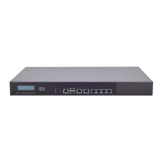
- Page 14 NCA-2512 User Manual NCA-2512A/B NCA-2512C Description With a Keypad System Power LED Indicators System Status HDD Activity Software reset Reset Button Console Port 1x Console port USB Port 2x USB 2.0 port MGMT Port 1x Management port IPMI Port 1x RJ45 for IPMI (IPMI card required) GbE &...
- Page 15 Chapter 1: Product Overview Description Rear PCIe Expansion 1x PCIex8 Expansion slot (Riser card required) (HH/HL) Cooling Fans 2x swappable independent fan Power Button 1x ATX Power button Power Supply 2x 300W PSU Note: Please refer to Appendix A: LED Indicator Explanations for description of the LED Indicators (including those on MGMT Port, IPMI Port, GbE, SFP+ Ports and HDD trays)
- Page 16 NCA-2512 User Manual The block diagram indicates how data flows among components on the motherboard. Please refer to the following figure for your motherboard’s layout design. Support up to DDR4 2400MHz mSATA UDIMM/ECC/RDIMM SATA 3.0 x3 PCIe x8 2x PCIe x4...
-
Page 17: Chapter 2: Motherboard Information
Chapter 2: Motherboard Information The motherboard layout shows the connectors and jumpers on the board. Refer to the following picture as a reference of the pin assignments and the internal connectors. - Page 18 NCA-2512 User Manual ATX1: 24-Pin ATX Power Connector Description Description Description Description +3.3V -12V +3.3V +3.3V PSON- Ground Ground Ground Ground Ground Power Good Ground Ground +12V Stand-By 5V 3.3V Ground +12V ATX2: 4-pin Power Connector Description Description +12V +12V JSATA2 &...
- Page 19 Chapter 2: Motherboard Information SW3: Reset Switch (reserved for debugging) Description Description FP_RST_SEL FP_RST_SEL SW1: PSON power switch (reserved for debugging) Description Description FP_SWIN_R FP_SWIN_R J21: Reset Description Description FP_SWIN_R CONN2: PSON power Description Description FP_SWIN_R JRESET1: Controls the software reset method of the Reset button on front panel. Description Description SW reset...
- Page 20 NCA-2512 User Manual JTPM1: TPM Description Description LPC_SERIRQ SOC_LPC_FRAME_N CLK_LPC_OUT SOC_LPC_LAD0 SOC_LPC_LAD1 P3V3_STBY SOC_LPC_LAD2 SOC_LPC_LAD3 P3V3_A CPLD_TPM_RESET_N Ground JLCM1: LCM Description Description Description Description LSTIN IOGND LPD1 LPD0 LAFD LINIT LPD5 LPD4 LPD3 LPD2 LPD7 LPD6 GPIO VCC3 VCC3 COMB2: COM PORT...
- Page 21 Chapter 2: Motherboard Information JOPMA1: OPMA CON7 RSVD RSVD OPMA RSVD RSVD DVI_TX0_H LDRQ_L DVI_TX0_L LFRAME_L LAD0 DVI_TX1_H LCLKRUN_L DVI_TX1_L LAD1 LAD2 DVI_TX2_H LAD3 DVI_TX2_L SERIRQ LRST_L DVI_TXCLK_H LCLK DVI_TXCLK_L DVI-I RSVD DVI_DDC_DATA RSVD DVI_DDC_CLK RSVD I2C_PRIV0_SCL ANALOG_DDC_DATA I2C_PRIV0_SDA ANALOG_DDC_CLK I2C_IPMB_SCL ANALOG_RED I2C_IPMB_SDA...
- Page 22 NCA-2512 User Manual JCMOS1: Clear CMOS Description Description Normal (Default) Clear CMOS Warning: After clearing CMOS or when PXE boot is enabled, the system boot-up time is doubled. JRTC1: RTC Description Description Normal (Default) Clear RTC JOPEN1: Case open Description...
- Page 23 Chapter 2: Motherboard Information J9: Gen3 Bypass Firmware Update Description Description Normal (Default) Firmware Update J80PORT1: 80Port Debug Description Description LAD1 RST- LAD0 LRAME- POWER LAD3 LAD2 JPLD1: Altera CPLD Description Description JTAG_PLD_TCK JTAG_PLD_TDO P3V3_STBY JTAG_PLD_TMS JTAG_PLD_TDI...
- Page 24 NCA-2512 User Manual To reduce the risk of personal injury, electric shock, or damage to the system, please remove all power connections to completely shut down the device. Also, please wear ESD protection gloves when conducting the steps narrated in this chapter.
-
Page 25: Chapter 3: Hardware Setup
Chapter 3: Hardware Setup 1. Check the accessory pack for the following items: 1x Screw Pack 2x Ear Brackets 2. Align the bracket to the side of the chassis and make sure the screw-holes are matched, and then secure the bracket onto the chassis with three provided screws. - Page 26 NCA-2512 User Manual 1. Check the package contents of the Slide Rail Kit. The kit shall include the following items: 1x pack of M4X4L screws (for securing the Rail Brackets on the system) 1x pack of 7.1 Round Hole screws (for securing the system on...
- Page 27 Chapter 3: Hardware Setup 5. Align the bracket to the side of the chassis and make sure the screw- holes are matched, and then secure the bracket onto the chassis with three provided M4X4L screws. Align the screws with the holes indicated on the brackets and the screw holes on the side of the chassis.
- Page 28 NCA-2512 User Manual 9. For the rear rack installation, slide the rail to aim and engage the bolts on the rail’s rear end with the two available holes on the post, and the rail assembly will click into place. Clic 10.
- Page 29 Chapter 3: Hardware Setup 12. While pushing in the system, also push and hold the Rail Lock tab on both brackets. Rail Lock Push the system all the way in until it stops. To remove the system from the rack, gently pull it outwards, towards you, while pushing the Release Tab on both sides of the brackets.
- Page 30 NCA-2512 User Manual To enter the BIOS setup utility, simply follow the steps below: 1. Boot up the system. 2. Press <Delete> during the boot-up if you connect a keyboard to this unit. But if you connect a PC to this unit through console USB/Serial connection, then press <Tab>.
-
Page 31: Chapter 4: Bios Setup
Chapter 4: BIOS Setup Setup main page displays a description of BIOS information and project version information. You can also set up the System Time and System Date here. (The screenshots presented in the section are for reference only) - Page 32 NCA-2512 User Manual Use [←] [→] to select [Advanced] setup screen. Under this screen, you may use [↑] [↓] to select an item you want to configure.
- Page 33 Chapter 4: BIOS Setup This option allows you to configure parameters about BIOS support for the security device. Press <Enter> to access the submenu. The default is “Enabled”.
- Page 34 NCA-2512 User Manual This option allows you to configure parameters about Super IO Chip. Press <Enter> to access the submenu. Select Serial Port 1 Configuration or Serial Port 2 Configuration to enter sub setting screen. The default is “Enabled”.
- Page 35 Chapter 4: BIOS Setup This option allows you to configure Smart Fan properties and monitor the fan status.
- Page 36 NCA-2512 User Manual Enter “Smart Fan Control” to change fan mode. The default is “Smart Fan Mode”.
- Page 37 Chapter 4: BIOS Setup If with the case’s support, enabling this option will have the unit sound when someone opens the case of this unit, which is considered against your organization’s policy. The default is “Disabled”.
- Page 38 NCA-2512 User Manual This option allows you to configure Digital I/O pin properties. Select the desired pin and press <Enter> to modify. The default is “Output Low”.
- Page 39 Chapter 4: BIOS Setup This option allows you to enable or disable Watchdog Timer function. The default is “Disabled”.
- Page 40 NCA-2512 User Manual This option allows you to configure parameters about serial port console redirection. Press <Enter> to access the submenu. The default is “Enabled”.
- Page 41 Chapter 4: BIOS Setup Console Redirection Settings Select this item to enter the setting sub-menu. These settings specify how the host computer and the remote computer will exchange data. Both computers should have the same or compatible settings. Item Value Description VT100: ASCII char set.
- Page 42 NCA-2512 User Manual VT-UTF8 Combo Key Disabled Enable VT-UTF8 Combination Key Support for Support Enabled ANSI/VT100 terminals Disabled With this mode enabled only text will be sent. Recorder Mode Enabled This is to capture Terminal data. VT100 LINUX XTERM86 Putty KeyPad Select FunctionKey and KeyPad on Putty.
- Page 43 Chapter 4: BIOS Setup This option allows you to configure parameters to be programmed into PCI Latency Timer Register.
- Page 44 NCA-2512 User Manual PCI Express Settings This option allows you to enable or disable PCI Express Device Relaxed Ordering.
- Page 45 Chapter 4: BIOS Setup PCI Express GEN 2 Settings This option allows you to enable or disable PCI ExpressGEN2 related setting.
- Page 46 NCA-2512 User Manual This option allows you to enable or disable UEFI Network Stack. The default is “Disabled “.
- Page 47 Chapter 4: BIOS Setup This option allows you to enable or disable ROM execution settings. Item Value Description Disabled CSM Support Enables or disables CSM Support Enabled Do Not Launch Controls the execution of UEFI and Network UEFI Legacy PXE OpROM Legacy Do Not Launch Controls the execution of UEFI and...
- Page 48 NCA-2512 User Manual This option allows you to change USB configuration parameters. Legacy USB Support Item Value Description Enables Legacy support. “Auto“ disables legacy support if no USB Enabled devices are connected. “Disabled“ will Legacy USB Support Disabled keep USB devices available only for EFI Auto applications.
- Page 49 Chapter 4: BIOS Setup 10 sec Set USB mass storage device Start Unit 20 sec Device reset time-out: command time-out (10, 20, 30 or 40 30 sec seconds). Default is “20 sec “. 40 sec Set the maximum time the device will take before it properly reports itself to Device power-up Auto...
- Page 50 NCA-2512 User Manual Use [←] / [→] to select the Chipset menu item from the BIOS setup screen to enter the IntelRCSetup Setup screen. Users can select any of the items in the left frame of the screen.
- Page 51 Chapter 4: BIOS Setup Item Value Description Enables or disables EIST. GV3 and TM1 must be enabled for TM2 to be available. Disable EIST(GV3) GV3 must be enabled for Turbo. Auto - Enabled Enable for B0 CPU stepping, all others disabled, change setting to override.
- Page 52 NCA-2512 User Manual...
- Page 53 Chapter 4: BIOS Setup This option enables or disables fast boot which skips memory training and attempts to boot using last known good configuration. The default is “Enabled”.
- Page 54 NCA-2512 User Manual This option allows you to configure SATA Controller properties. SATA Configuration Enables/Disables SATA Controller if supported by current CPU SKU. The default is “Enabled”. Enabling the SATA controller, you can respectively modify the JSATA1, JSATA1 and mSATA...
- Page 55 Chapter 4: BIOS Setup Use [←] [→] to select Security setup screen. Under this screen, you may use [↑] [↓] to select an item you would like to configure. Administrator Password & User Password Item Description Administrator If ONLY the Administrator's password is set, then this only limits access to Password Setup and is only asked for when entering Setup.
- Page 56 NCA-2512 User Manual Secure Boot Enter Secure Boot page for more related settings. Item Value Description Secure Boot is activated when Platform Key(PK) is enrolled, System mode is Disabled Attempt Secure Boot User/Deployed, and CSM function is Enabled disabled Secure Boot mode selector:...
- Page 57 Chapter 4: BIOS Setup Key Management Item Value Description Allows you to provision factory default Provision Factory Disabled Secure Boot keys when System is in Setup Defaults Enabled Mode. Install Factory Default Forces System to enter User Mode - None keys install all Factory Default keys Allows the image to run in Secure Boot...
- Page 58 NCA-2512 User Manual Select the Boot menu item from the BIOS setup screen to enter the Boot Setup screen. Description Item Value Disabled Quiet Boot Enables or disables Quiet Boot option. Enabled LEGACY Boot mode select UEFI Select boot mode.
- Page 59 Select the Save and Exit menu item from the BIOS setup screen to enter the Save and Exit Setup screen. Users can select any of the items in the left frame of the screen. Save Changes and Exit When you have completed the system configuration, select this option to save the changes and Exit from BIOS Setup, so the new system configuration parameters can take effect.
- Page 60 NCA-2512 User Manual The status explanations of LED indicators on Front Panel are as follows: System Power System Status HDD Activity System Power Solid Green The system is powered on The system is powered off System Status This LED indicator is programmable. You could program it to display the operating status with the...
- Page 61 Appendix A: LED Indicator Explanations Link Activity Speed Link Activity Solid Green Link has been established and there is no activity on this port Blinking Green Link has been established and there is activity on this port No link has been established Speed Solid Green Operating as a 10-Gigabit connection...
-
Page 62: Watchdog Timer
-swt xxx (Set Watchdog Timer 1-255 seconds and start to count-down) wd_tst -stop (Stop Watchdog Timer) For a reference utility that contains sample code for watchdog function programming, please visit http://www.lannerinc.com/support/download-center/drivers, enter the product category and download the utility package of NCA-2512. -
Page 63: Appendix C: Setting Up Console Redirections
Appendix C: Setting up Console Redirections Console redirection lets you monitor and configure a system from a remote terminal computer by re- directing keyboard input and text output through the serial port. The following steps illustrate how to use this feature. The BIOS of the system allows the redirection of the console I/O to a serial port. With this configured, you can remotely access the entire boot sequence through a console port. - Page 64 Bypass Gen 3 employs a programming method to control the bypass function by software. There are typically two types of communication status for the bypass function, one is “Normal“ and another is “Bypass“ status. Furthermore, the Lanner Bypass software is capable of controlling the bypass status in the following 3 instances.
- Page 65 Appendix E: Installing Intel® LAN Controller Driver for Linux For the latest driver update, please visit Intel® download center at https://downloadcenter.intel.com/, use the keyword search or the filter to access the driver’s product page, and then download the latest controller driver as well as the ReadMe document.
- Page 66 NCA-2512 User Manual 1. All products are under warranty against defects in materials and workmanship for a period of one year from the date of purchase. 2. The buyer will bear the return freight charges for goods returned for repair within the warranty period;...
-
Page 67: Appendix F: Terms And Conditions
Appendix F: Terms and Conditions When requesting RMA service, please fill out the following form. Without this form enclosed, your RMA cannot be processed.
Need help?
Do you have a question about the NCA-2512 and is the answer not in the manual?
Questions and answers