Advertisement
Quick Links
Advertisement

Subscribe to Our Youtube Channel
Related Manuals for Lanner NCA-5230


Summary of Contents for Lanner NCA-5230
- Page 1 Network Appliance Platform NCA-5230 User Manual Version: 1.0 Date of Release:2022-06-14...
-
Page 2: Technical Support
- assumed to be qualified in the servicing of computer equipment, such as professional system integrators or service personnel and technicians. The latest version of this document can be found on Lanner’s official website, available either through the product page or through the Lanner Download Center page with a login account and password. - Page 3 NCA-5230 User Manual Taiwan Corporate Headquarters China Lanner Electronics Inc. Beijing L&S Lancom Platform Tech. Co., Ltd. 7F, No.173, Sec.2, Datong Rd. Guodong LOFT 9 Layer No. 9 Huinan Road, Xizhi District, New Taipei City 22184, Huilongguan Town, Changping District, Beijing...
- Page 4 NCA-5230 User Manual This document is copyrighted © 2022 by Lanner Electronics Inc. All rights are reserved. The original manufacturer reserves the right to make improvements to the products described in this manual at any time without notice. No part of this manual may be reproduced, copied, translated, or transmitted in any form or by any means without the prior written permission of the original manufacturer.
- Page 5 NCA-5230 User Manual Follow these guidelines to ensure general safety: Keep the chassis area clear and dust-free during and after installation. Do not wear loose clothing or jewelry that could get caught in the chassis. Fasten your tie or scarf and roll up your sleeves.
- Page 6 The installation of this product must be performed by trained specialists; otherwise, a non-specialist might create the risk of the system’s falling to the ground or other damages. Lanner Electronics Inc. shall not be held liable for any losses resulting from insufficient strength for supporting the system or use of inappropriate installation components.
-
Page 7: Safety Warning
NCA-5230 User Manual Elevated Operating Ambient - If installed in a closed or multi-unit rack assembly, the operating ambient temperature of the rack environment may be greater than room ambient. Therefore, consideration should be given to installing the equipment in an environment compatible with the maximum ambient temperature (Tma) specified by the manufacturer. - Page 8 NCA-5230 User Manual Before turning on the device, ground the grounding cable of the equipment. Proper grounding (grounding) is very important to protect the equipment against the harmful effects of external noise and to reduce the risk of electrocution in the event of a lightning strike.
- Page 9 NCA-5230 User Manual Main Features ............................ 11 Package Content..........................11 Optional Accessories Kits ........................11 Ordering Information ......................... 11 System Specifications ......................... 12 Front Panel ............................13 Rear Panel ............................14 Motherboard Information........................15 Opening the Chassis ........................... 21 Installing the System Memory ......................22 Installing the IPMI Card (Optional) .....................
- Page 10 NCA-5230 User Manual Security ............................... 76 Boot Menu ............................79 Save and Exit Menu ..........................80 Remote Server Management ......................82 Warranty Policy ..........................87...
- Page 11 NCA-5230 User Manual Powered by Intel® Xeon® i9/i7/i5/i3/Pentium/Celeron CPU (Codenamed Comet Lake S), NCA-5230 supports up to eight GbE RJ45 ports, eight SFP ports, with four bypass features. In addition to 2x NIC module slots for expansion, 2x 2.5” HDD/SDD bays for addition storage support and up to 128GB of DDR4 system memory. NCA-...
- Page 12 NCA-5230 User Manual Form Factor 1U 19“ Rackmount Intel® Xeon® i9/i7/i5/i3/Pentium/Celeron CPU Processor Options (Codenamed Comet Lake S) Platform CPU Socket 1x LGA 1200 Socket Chipset CML-S W480E PCH BIOS AMI SPI Flash BIOS Technology DDR4 ECC or Non-ECC UDIMM, up to 2933MHz System Memory Max.
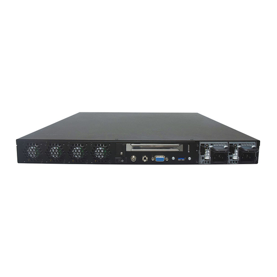
- Page 13 NCA-5230 User Manual Description 16x2 character LCM Keypad 4x keypad Reset Button 1x Reset Button USB Port 2x USB 3.0 ports Console Port 1x RJ45 Console Port MGMT Port 1x RJ45 MGMT Port; Shared IPMI port (Optional) System Power LED Indicators...
- Page 14 NCA-5230 User Manual Description Cooling Fan 4x cooling fans with SMART function PCIe Expansion Slot Optional FH/HL Size PCIe Slot for 1x PCIex8 or 2x PCIE4 SKU A: 2x 350W AC Redundant PSU (N+1 design); or Redundant PSU SKU B: 1x 350W Single PSU...
- Page 15 NCA-5230 User Manual The motherboard layout shows the connectors and jumpers on the board. Refer to the following picture as a reference for the pin assignments and the internal connectors. The pin headers on the motherboard are often associated with essential functions. With the shunt (Jumper) pushed down on the designated pins (the pin numbers are printed on the circuit board, surrounding the pin header), particular features can be enabled or disabled.
- Page 16 NCA-5230 User Manual 1. JRST1: Reset (Default 2-3) Controls the reset method of the Reset button on the panel Pin No. Description HW Reset SW Reset (Default) 2. JPWR1: Power – ON Button (Must be connected) 3. JUSB3: USB 3.0 Pin Header (2 Ports) 4.
- Page 17 NCA-5230 User Manual 23. JRISER1: PCH PCIe GEN3 Slot (only x4) 24. JVGA1: BMC VGA CONN1 Pin No. Description Pin No. Description CRT_RED CRT_GREEN CRT_BLUE HSYNC VSYNC DDC_DATA DDC_CLK 25. OPMA1: IPMI AST2500 Socket 26. J80P1: 80Port Pin Header Pin No.
- Page 18 NCA-5230 User Manual 34. JSATA PW1: SATA 5V Power Connector (only provide 5V) 35. JSATAPW2: SATA 5V Power Connector (only provide 5V) Pin No. Description 36. U4: I210 for MGMT (via PCIe) or IPMI LOM Port (via NCSI) 37. JSATA1: SATA3 CONN 38.
- Page 19 NCA-5230 User Manual 1. JUSB3: INT USB 3.0 Pin Header (2 Ports) 2. JIO1: 3.3V / USB OVC / LED / MDI / Console / Reset Connector Pin No. Description Pin No. Description +V3P3S +V3P3S +V3P3S I210_MDI_0P +V3P3S I210_MDI_0N I210_MDI_1P...
- Page 20 NCA-5230 User Manual 3. LAN2: INT MGMT Port Pin Header 4. JRST1: Reset Button 5. JUSB1: USB 3.0 5G 6. JUSB2: USB 3.0 5G 7. JCOM1: Console Port (Baud Rate: 115200) 8. JLOM1: MGMT/IPMI LOM Port 9. JLAN1: MGMT Port (Reserved) 10.
- Page 21 NCA-5230 User Manual To reduce the risk of personal injury, electric shock, or damage to the system, please remove all power connections to shut down the device completely. Also, please wear ESD protection gloves when conducting the steps in this chapter.
- Page 22 NCA-5230 User Manual The motherboard supports 4 memory slots for DDR4 UDIMM with speeds of up to 2933MHz. The CPU requires at least 2 memory modules to boot and run from. Total Slots Number of Channels 2 (2 DIMMs per channel)
- Page 23 NCA-5230 User Manual Recommended DIMM Population Scheme The table below shows the recommended schemes for DIMM population. To guarantee balanced system performance, please install identical DIMMs of the same capacity, speed, number of ranks, and from the same manufacturer. SLOT #...
- Page 24 NCA-5230 User Manual This system supports an IPMI module card through the OPMA1 slot, allowing system administrators to remotely manage and monitor system health. 1. Power off the system and open the chassis cover. Locate the IPMI socket on the motherboard.
- Page 25 NCA-5230 User Manual This system supports one TPM module card through the TPM slot. Follow the procedures below for installing the TPM module card. Power down the system and open the chassis cover. Locate the TPM pins on the motherboard.
- Page 26 NCA-5230 User Manual This appliance system supports the M.2 storage module card (2242/2280 B+M Key) through the M2_1 slot. 1. Power off the system and open the cover. Locate the M.2 slot on the motherboard. 2. Align the notch of the storage card with the socket in the pin slot.
- Page 27 NCA-5230 User Manual The HDD/SSD bay supports two 2.5” SATA HDDs or SSDs as data storage. Please follow the steps below for installation. 1. Power off the system and open the chassis cover. Locate the 2.5” disk trays on the lower left side inside the system.
- Page 28 NCA-5230 User Manual 4. Attach the SATA data cables and the SATA power cables to the HDD/SSD disks. 5. Place the tray with the disk drives installed, back to its original spot inside the system. Secure with the original three (3) screws.
- Page 29 NCA-5230 User Manual This system can accommodate four NIC slim type modules on the front panel, with Slot 1 and Slot 2 occupied by LAN ports (8x RJ45 & 8x SFP ports). Please see Slot layout and PCIe Interface: SLOT1...
- Page 30 NCA-5230 User Manual Power supply units may wear down eventually. Please be noted that this system supports 600W PSU. Please prepare the power supply units matching this capacity. 1. On the rear panel, locate the power supply units and disconnect the power cords.
- Page 31 NCA-5230 User Manual There are various methods to mount this system based on your application and the environment. This system came with two types of mounting kits for a typical rack or enclosure mounting installation or installing this system in a rack:...
- Page 32 NCA-5230 User Manual The Ear Brackets come with six screws, as shown below. Take an ear bracket, align the holes on it with those on the side of the system, and lock it onto the system with three provided screws. Do the same to the other ear bracket.
- Page 33 NCA-5230 User Manual Fully stretched slide rail: Outer Channel Inner Channel Rail Bracket 1. Unpack a slide rail and slide the inner channel to its end. 2. Slide the rail bracket out to its end. Release Tab 3. To detach the rail bracket from the...
- Page 34 NCA-5230 User Manual 1. This slide-rail kit does NOT require screw-fixing. Aim at 3 available screw holes on the rack front and lock it by clipping the rail’s front end to the post, as shown in the image Use this clamp below.
- Page 35 NCA-5230 User Manual 2. Hold the chassis with its front facing you, lift and gently insert it by aligning with slide-rail assemblies as shown in the image, and then push the unit into the cabinet. 3. Keep sliding the rails in until they stop about halfway.
- Page 36 NCA-5230 User Manual The system has AMI BIOS built-in, with a SETUP utility that allows users to configure required settings or to activate certain system features. Pressing the <Tab> or <DEL> key immediately allows you to enter the Setup utility.
- Page 37 NCA-5230 User Manual Setup main page contains BIOS information and project version information. Feature Description BIOS Vendor: American Megatrends Core Version: AMI Kernel version, CRB code base, X64 Compliancy: UEFI version, PI version BIOS Information Project Version: BIOS release version...
- Page 38 NCA-5230 User Manual Select the Advanced menu item from the BIOS setup screen to enter the “Advanced” setup screen. Users can select any of the items in the left frame of the screen.
- Page 39 NCA-5230 User Manual Feature Options Description Disabled Enable/Disable moving of DRAM contents to PRM C6DRAM memory when CPU is in C6 state Enabled Software Guard Disabled Enable/Disable Software Guard Extensions (SGX) Extensions (SGX) Enabled...
- Page 40 NCA-5230 User Manual Disabled CPU Flex Ratio Override Enable/Disable CPU Flex Ratio Programming Enabled This value must be between Max Efficiency Ratio (LFM) CPU Flex Ratio Settings and Maximum non-turbo ratio set by Hardware (HFM). Disabled Hardware Prefetcher To turn on/off the MLC streamer prefetcher.
- Page 41 NCA-5230 User Manual...
- Page 42 NCA-5230 User Manual Feature Options Description Max Battery Boot performance Max Non-Turbo Select the performance state that the BIOS will set starting mode Performance from reset vector. Turbo Performance" Disabled Intel® SpeedStep Allows more than two frequency ranges to be supported.
- Page 43 NCA-5230 User Manual Feature Options Description Disabled When Disabled ME will be put into ME Temporarily Disabled ME State Enabled Mode.
- Page 44 NCA-5230 User Manual Feature Options Description Me FW Image Disabled Enable/Disable Me FW Image Re-Flash function. Re-Flash Enabled...
- Page 45 NCA-5230 User Manual Feature Options Description Enables or disables BIOS support for security device. By Security Device Enabled disabling this function, OS will not show Security Device. TCG Support Disabled EFI protocol and INT1A interface will not be available.
- Page 46 NCA-5230 User Manual Feature Options Description Enables or disables BIOS support for security device. By disabling Security Device Enabled this function, OS will not show Security Device. TCG EFI protocol Support Disabled and INT1A interface will not be available. Enables or disables Security Device.
- Page 47 NCA-5230 User Manual Feature Options Description Enables or disables BIOS support for security device. By disabling Security Device Enabled this function, OS will not show Security Device. TCG EFI protocol Support Disabled and INT1A interface will not be available. Enabled SHA-1 PCR Bank Enables or disables SHA-1 PCR Bank.
- Page 48 NCA-5230 User Manual Schedules an Operation for the Security Device. None Pending operation NOTE: Your computer will reboot during restart in order to change TPM Clear State of Security Device. Enabled Platform Hierarchy Enables or disables Platform Hierarchy. Disabled Enabled Storage Hierarchy Enables or disables Storage Hierarchy.
- Page 49 NCA-5230 User Manual...
- Page 50 NCA-5230 User Manual Feature Options Description Enabled Serial Port Enables or disables Serial Port 1. Disabled Device Settings IO=3F8h; IRQ = 4...
- Page 51 NCA-5230 User Manual Feature Options Description Enabled Serial Port Enables or disables Serial Port 2. Disabled Device Settings IO=2F8h; IRQ = 3...
- Page 52 NCA-5230 User Manual Feature Options Description Smart Fan Control None Smart Fan Parameters...
- Page 53 NCA-5230 User Manual Feature Options Description CPU Smart Manual Mode Smart Fan Mode select Fan Mode Smart Fan Mode Target Temp T1 Input Target Temperature (Range:0 - 127) Target Temp T2 Input Target Temperature (Range:0 - 127) Target Temp T3...
- Page 54 NCA-5230 User Manual Feature Options Description COM0 Enabled Enables or disables Console Redirection Console Redirection Disabled...
- Page 55 NCA-5230 User Manual Feature Options Description VT100: ASCII char set VT100 VT100+:Extends VT100 to support color, function keys, etc. VT100+ Terminal Type VT-UTF8:Uses UTF8 encoding to map Unicode chars onto 1 VT-UTF8 or more bytes ANSI ANSI: Extended ASCII char set...
- Page 56 NCA-5230 User Manual VT-UTF8 Combo Disabled Enables VT-UTF8 Combination Key Support for ANSI/VT100 Key Support Enabled terminals Disabled With this mode enabled, only text will be sent. This is to Recorder Mode Enabled capture Terminal data. Disabled Resolution 100x31 Enables or disables extended terminal resolution...
- Page 57 NCA-5230 User Manual Feature Options Description Redirection COM0 Select a COM port to display redirection of Legacy OS and COM Port Legacy OPROM Messages. 80x24 On Legacy OS, the Number of Rows and Columns supported Resolution 80x25 redirection. When Bootloader is selected, Legacy Console Redirection is...
- Page 58 NCA-5230 User Manual...
- Page 59 NCA-5230 User Manual Feature Options Description Globally Enables or Disables 64bit capable Devices to be Disabled Above 4G Decoding Decoded in Above 4G Address Space (Only if System Supports Enabled 64 bit PCI Decoding).
- Page 60 NCA-5230 User Manual Feature Options Description Enables Legacy USB support. Enabled Auto option disables legacy support if no USB devices are Legacy USB Support Disabled connected; Disabled option will keep USB devices available only Auto for EFI applications. Enabled This is a workaround for OSes without XHCI hand-off support.
- Page 61 NCA-5230 User Manual Feature Options Description Disabled Network Stack Enables or disables UEFI Network Stack Enabled IPv4 PXE Support Disabled Enable/Disable IPv4 PXE boot support. If disabled, IPv4 PXE boot Enabled support will not be available. IPv4 HTTP Support Disabled Enable/Disable IPv4 HTTP boot support.
- Page 62 NCA-5230 User Manual Feature Options Description Disabled CSM Support Enables or disables CSM Support Enabled...
- Page 63 NCA-5230 User Manual...
- Page 64 NCA-5230 User Manual Feature Options Description Control PXE Boot Disabled Enable/Disable PXE function from Enabled...
- Page 65 NCA-5230 User Manual Select the Chipset menu item from the BIOS setup screen to enter the Chipset setup screen. Users can select any of the items in the left frame of the screen.
- Page 66 NCA-5230 User Manual Feature Options Description Disabled VT-d VT-d capability Enabled Enable/Disable above 4GB MemoryMappedIO BIOS assignment. Above 4GB MMIO Disabled This is enabled automatically when Aperture Size is set to BIOS assignment Enabled 2048MB. Disabled X2APIC Opt Out Enable/Disable X2APIC_OPT_OUT bit...
- Page 67 NCA-5230 User Manual Feature Options Description Maximum Memory Auto Maximum Memory Frequency Selections in Mhz. Valid values Frequency 1067~ 3200 should match the refclk, i.e. divide by 133 or 100 Maximum Value of TOLUD. Dynamic assignment would adjust Dynamic Max TOLUD TOLUD automatically based on largest MMIO length of installed 1 GB ~ 3.5GB...
- Page 68 NCA-5230 User Manual Feature Options Description Disabled Enable Root Port Enabled Enable or Disable the Root Port Auto Auto Gen1 Max Link Speed Configure PEG 0:1:0 Max Speed Gen2 Gen3 Sets the upper limit on power supplied by slot. Power limit (in...
- Page 69 NCA-5230 User Manual Feature Options Description Detect Non- Disabled Detect Non-Compliance PCI Express Device in PEG Compliance Device Enabled...
- Page 70 NCA-5230 User Manual Feature Options Description Quiet Serial IRQ Mode Configure Serial IRQ Mode. Continuous Power On Restore AC Specify what state to go to when power is re-applied after a Power Off Power Loss power failure (G3 state). Last State...
- Page 71 NCA-5230 User Manual...
- Page 72 NCA-5230 User Manual Feature Options Description PCI Express Disabled Control the PCI Express Root Port. Root Port 1 Enabled Disabled Set the ASPM Level:Force L0s - Force all links to L0s StateAUTO ASPM 0 - BIOS auto configureDISABLE - Disables ASPM...
- Page 73 NCA-5230 User Manual...
- Page 74 NCA-5230 User Manual Feature Options Description Enabled SATA Controller(s) Enable/Disable SATA Device. Disabled AHCI SATA Mode Selection Determines how SATA controller(s) operate. Intel RST Aggressive LPM Enabled Enable PCH to aggressively enter link power state. Support Disabled Enabled Port 0...
- Page 75 NCA-5230 User Manual Feature Options Description Disabled Enable will lock bytes 38h-3Fh in the lower/upper 128-byte bank RTC Memory Lock Enabled of RTC RAM Disabled Enable/Disable the PCH BIOS Lock Enable feature. Required to BIOS Lock Enabled be enabled to ensure SMM protection of flash.
- Page 76 NCA-5230 User Manual Select the Security menu item from the BIOS setup screen to enter the Security Setup screen. Users can select any of the items in the left frame of the screen. Feature Description Administrator If ONLY the Administrator's password is set, it only limits access Password to Setup and is only asked for when entering Setup.
- Page 77 NCA-5230 User Manual Feature Options Description Disabled Secure Boot is activated when Platform Key (PK) is enrolled, Secure Boot Enabled System mode is User/Deployed, and CSM function is disabled. Customizable Secure Boot mode: In Custom mode, Secure Boot Standard Secure Boot Mode...
- Page 78 NCA-5230 User Manual Feature Options Description Disabled Provision factory default keys on next re-boot only when System Factory Key Provision Enabled in Setup Mode. Force System to User Mode. Configure NVRAM to contain OEM- Restore Factory keys None defined factory default Secure Boot keys.
- Page 79 NCA-5230 User Manual Select the Boot menu item from the BIOS setup screen to enter the Boot Setup screen. Users can select any of the items in the left frame of the screen. Feature Options Description Setup Prompt The number of seconds to wait for setup activation key.
- Page 80 NCA-5230 User Manual Select the Save and Exit menu item from the BIOS setup screen to enter the Save and Exit Setup screen. Users can select any of the items in the left frame of the screen. ■Discard Changes and Exit Select this option to quit Setup without saving any modifications to the system configuration.
- Page 81 NCA-5230 User Manual ■Restore Defaults Restore default values for all setup options. Select “Yes” to load Optimized defaults. PS: The items under Boot Override may not have the same images. It would depend on devices connect on system.
- Page 82 NCA-5230 User Manual This document specifies the BMC firmware features of Lanner. The BMC firmware implements IPMI 2.0 based on ASPEED service processor. It performs all the BMC management tasks defined by IPMI 2.0. In addition, Lanner’s BMC firmware runs an embedded web-server for full configuration using Web UI, which has a low learning curve.
-
Page 83: System Health Monitoring
NCA-5230 User Manual System health monitoring The BMC implements system sensor monitoring feature. It could monitor voltage, temperature, and current of critical components. System Power Management The BMC implements chassis power and resets functions for system administrators to control and manage the system power behavior. -
Page 84: Virtual Media Redirection
NCA-5230 User Manual from the embedded web server. Support video recording, recorded videos to be downloaded & playable. • Virtual Media Redirection The BMC provides remote virtual CD, HD and FD redirection. CD image could be mounted directly in KVM window. - Page 85 NCA-5230 User Manual Get SDR Storage (0Ah) Get SDR Repository Time Storage (0Ah) SEL Device Commands Get SEL Info Storage (0Ah) Get SEL Allocation Info Storage (0Ah) Get SEL Entry Storage (0Ah) Delete SEL Entry Storage (0Ah) Clear SEL Storage (0Ah)
- Page 86 NCA-5230 User Manual System Power / Status / HDD Activity COLOR LED ACTION DESCRIPTION Green Steady System is powered ON POWER System is powered OFF Green Steady control by GPIO Steady control by GPIO STATUS System is powered OFF Amber...
- Page 87 NCA-5230 User Manual 1. All products are under warranty against defects in materials and workmanship for a period of one year from the date of purchase. 2. The buyer will bear the return freight charges for goods returned for repair within the warranty period, whereas the manufacturer will bear the after service freight charges for goods returned to the user.
- Page 88 NCA-5230 User Manual When requesting RMA service, please fill out the following form. Without this form enclosed, your RMA cannot be processed.
Need help?
Do you have a question about the NCA-5230 and is the answer not in the manual?
Questions and answers