
Subscribe to Our Youtube Channel
Related Manuals for Lanner NCA-5330


Summary of Contents for Lanner NCA-5330
- Page 1 Network Appliance Platforms Hardware Platforms for Network Computing NCA-5330 User Manual Version: 1.0 Date of Release:2024-07-19...
- Page 2 - assumed to be qualified in the servicing of computer equipment, such as professional system integrators, or service personnel and technicians. The latest version of this document can be found on Lanner’s official website, available either through the product page or through the Lanner Download Center page with a login account and password.
- Page 3 221 新北市汐止區 service@ls-china.com.cn 大同路二段 173 號 7 樓 T: +886-2-8692-6060 F: +886-2-8692-6101 contact@lannerinc.com Canada Lanner Electronics Inc. Lanner Electronics Canada Ltd 47790 Westinghouse Drive 3160A Orlando Drive Fremont, CA 94539 Mississauga, ON T: +1-855-852-6637 L4V 1R5 Canada F: +1-510-979-0689 T: +1 877-813-2132 sales_us@lannerinc.com...
- Page 4 Acknowledgment AMD and AMD EPYC are trademarks of Advanced Micro Devices, Inc. and/or its subsidiaries in the U.S. and/or other countries. Microsoft Windows and MS-DOS are registered trademarks of Microsoft Corp. All other product names or trademarks are properties of their respective owners. Federal Communication Commission Interference Statement This equipment has been tested and found to comply with the limits for a Class A digital device, pursuant to Part 15 of FCC Rules.
- Page 5 Safety Guidelines Follow these guidelines to ensure general safety: Keep the chassis area clear and dust-free during and after installation. Do not wear loose clothing or jewelry that could get caught in the chassis. Fasten your tie or scarf and roll up your sleeves.
- Page 6 The installation of this product must be performed by trained specialists; otherwise, a non-specialist might create the risk of the system’s falling to the ground or other damages. Lanner Electronics Inc. shall not be held liable for any losses resulting from insufficient strength for supporting the system or use of inappropriate installation components.
- Page 7 du bruit externe et réduire les risques d’électrocution en cas de foudre. Pour désinstaller l’équipement, débranchez le câble de mise à la terre après avoir éteint l’appareil. Un câble de mise à la terre est requis et la zone reliant les sections du conducteur doit faire plus de 4 mm2 ou 10 AWG. Grounding Procedure for This Device Connect the grounding cable to the ground.
-
Page 8: Table Of Contents
Table of Contents Chapter 1: Product Overview ............... 10 Package Content ..........................10 Optional Accessories ......................... 10 Ordering Information ........................10 System Specifications ........................11 Front Panel ............................12 Rear Panel ............................13 Motherboard Information ........................ 14 Chapter 2: Hardware Setup ..............24 Opening the Chassis .......................... - Page 9 Save and Exit Menu ........................... 78 Server Mgmt ............................. 80 Appendix A: LED indicator explanations ..........88 Appendix B: Dual BIOS Gen 2 Function ..........89 Appendix C: Redundant Power Module Behavior ......91 Appendix D: Fan Sequence ..............92 Appendix E: Smart Power and Reset Button ........
-
Page 10: Chapter 1: Product Overview
CHAPTER 1: PRODUCT OVERVIEW The NCA-5330 makes available accelerated workloads with its high-per-core-performance, reduced energy consumption and minimized TCO: its outstanding hardware features make it the ideal platform for application delivery, mobile edge computing, WAN optimization, DPI/IPS/IDS, NFV/SDN and NGFW/UTM. -
Page 11: System Specifications
System Specifications Form Factor 1U 19” Rackmount AMD EPYC 9004 Series Processors Processor Options (Codenamed Genoa/Bergamo) CPU Socket AMD SP5 Platform CPU TDP 360W Chipset Security Acceleration AMD Enhanced Security BIOS AMI SPI Flash BIOS Technology DDR5 4800MHz R-DIMM System Memory Max. -
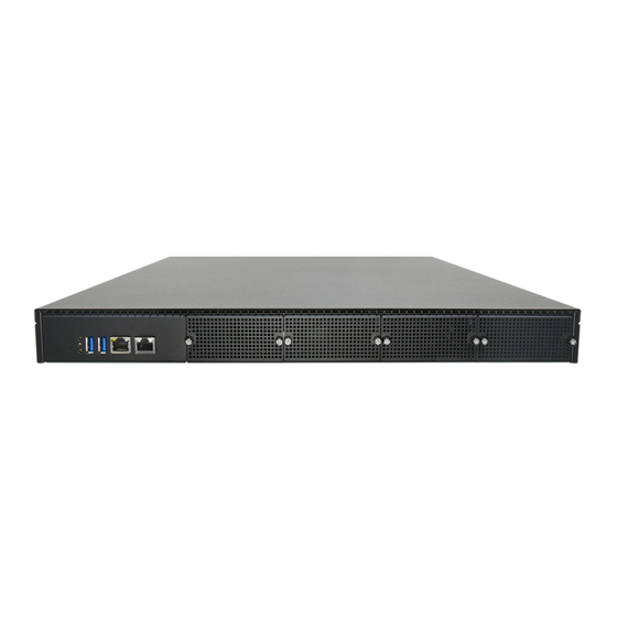
Page 12: Front Panel
Front Panel F4 F5 Description Reset button 1x Reset Button System Power LED Indicators System Status HDD Activity USB Port 2x USB 3.0 Ports LAN Port 1x RJ45 LAN Port w/ LED for MGMT & Share w/ LOM (Optional) Console Port 1x RJ45 Console Port 4x NCS2 Slim Type NIC Module;... -
Page 13: Rear Panel
Rear Panel Description Power Supply 2x 1300W AC 1+1 Redundant CRPS Power Supply Power Switch 1x Power Switch I/O Button Alarm Reset 1x Alarm Reset Button Fans 5x Hot-swappable Cooling Fans ESD Jack 1x ESD Screw Hole Ground Hole 1x Ground Screw Hole... -
Page 14: Motherboard Information
Motherboard Information Block Diagram The block diagram indicates how data flows among components on the motherboard. Note: The Intel NCSI (Network Controller Sideband Interface) is limited to 100Mbps, despite sharing a connection with the Intel i210, which is capable of 1Gbps. This discrepancy occurs because the actual bandwidth for NCSI is constrained to 100Mbps, regardless of the 1Gbps speed capability of the Intel i210. - Page 15 Motherboard Layout The motherboard layout shows the connectors and jumpers on the board. Refer to the following picture as a reference of the pin assignments and the internal connectors. Note: JRISER1a and JRISER1b combined support one PCIEx16 slot, while JRISER1a alone supports a single PCIEx8 slot.
- Page 16 Internal Jumpers and Connectors The pin headers on the motherboard are often associated with important functions. With the shunt (Jumper) pushed down on the designated pins (the pin numbers are printed on the circuit board, surrounding the pin header), certain feature can be enabled or disabled. While changing the jumpers, make sure your system is turned off.
- Page 17 JSPI_TPM1 Pin No. Description Pin No. Description SPI_HD1# SPI_CS1# SPI_CS0#_DUAL +P3V3_SPI_PCH_AUX SPI_MISO_TPM HEADER_SPI_PCH_IO3 SPI_CLK_TPM SPI_MOSI_TPM IRQ_TPM_SPI#_R SPI_TPM_CS0# RST_PLTRST_PLD_B_N JSATAPW1 & 2 Pin No. Description +P12V +P5V JPWR1 Pin No. Description PWRON# JOPEN1 Pin No. Description PWRON# JFAN1~5: FAN Connector Pin No. Description +P12V_FAN +P12V_FAN...
- Page 18 JFAN_MID Pin No. Description +P12V_FAN RPM Sense RPM Sense PWM Status J1: HDT Connector Pin No. Description Pin No. Description +P_VDD_18_SUS HDT_HDR_TCK HDT_HDR_TMS HDT_HDR_TDI HDT_HDR_TDO HDT_HDR_TRST_L HDT_HDR_PWROK_R HDT_CONN_XTRIG_L6 HDT_HDR_RESET_L_R HDT_CONN_XTRIG_L7 HDT_CONN_XTRIG_L5 HDT_HDR_DBREQ_L HDT_HDR_TESTEN +P_VDD_18_SUS HDT_HDR_TCK J2: BP Pin No. Description Pin No.
- Page 19 PJ2: PWR IC I2C Connector Pin No. Description P0_REGS_I2C_SDA P0_REGS_I2C_SCL JBMC_SGPI01 Pin No. Description SGPIO_DEBUG_PLD_CLK SGPIO_DEBUG_PLD_DOUT SGPIO_DEBUG_PLD_DIN SGPIO_DEBUG_PLD_LD_N Front Panel RST Button SW10 Power ON Button JSATA1~4 Pin No. Description TX_P TX_N RX_N RX_P...
- Page 20 POWER CONNECTOR ATX4: 24-Pin Power Connector Pin No. Description Pin No. Description 12VSB JNGFF3...
- Page 21 JIOB: IO Board Jumper Setting To short the designated pins, push the jumper down on them so that they become SHORT. To make the pins setting OPEN, simply remove the jumper cap. 2-Pin Header 3-Pin Header 4-Pin Header Open Short Open (1-2) Jumped Open...
- Page 22 JCMOS1 (1-2) 1-2 Normal 2-3 Clear CMOS Pin No. Description +VRTC BMC_ASSERT_CLR_CMOS JRST1 (1-2) 1-2 SW Reset (Default) 2-3 HW Reset Pin No. Description FP_CPLD_RST# FP_RESET# P0_SYS_RESET_L JPMB1: PMBUS Pin No. Description Pin No. Description P3V3_SB ATX_PSON# ATXPWGD PMBUS_CLK PMBUS_DAT PMBUS_ALERT# J JDUAL1: Chip Select 1-2;...
- Page 23 J4 (1~2): Disable Dual BIOS Function 1-2: Disable Dual BIOS Pin No. Description DUAL_BIOS_SEL JCOM2 Pin No. Description Pin No. Description COM2_RX COM2_RTS COM2_TX COM2_CTS# +P5V...
-
Page 24: Chapter 2: Hardware Setup
CHAPTER 2: HARDWARE SETUP To reduce the risk of personal injury, electric shock, or damage to the system, please remove all power connections to shut down the device completely and wear ESD protection gloves when handling the installation steps. Opening the Chassis 1. -
Page 25: Installing The Cpu
Installing the CPU The LGA3647 processor features a complex design that requires assembly with specialized tools and careful handling by professionals. It is highly advised not to adjust, remove, or reinstall the processor yourself. If self- handling is unavoidable, ensure you thoroughly read the instructions provided in this section and possess the requisite knowledge and tools to comply with the guidelines. - Page 26 3. Carefully lift the inner frame using the blue tab and remove the protective cap. 4. Carefully insert the CPU, ensuring that the alignment corner marked on the CPU matches that of the metal frame. Secure the frame with the original one (1) screw. Alignment mark 5.
-
Page 27: Installing The System Memory
Installing the System Memory Each 4th Gen AMD EPYC processor (9004 Series) includes 12 Unified Memory Controllers (UMC). Each UMC controls a single memory channel, and each channel can be populated with either 1 DIMMs, as described above. The tables and images in this User Guide are examples for reference purposes only. UMC#: UMC on the AMD EPYC processor that controls the memory channel. - Page 28 Supported System Memory: Total Slots Number of Channels 8x channels;One DIMM per channel (1DPC) Supported DIMM Capacity 16GB 1Rx8;32GB 1Rx4;32GB 2Rx8;64GB 2Rx4 Memory Size Maximum 512GB RDIMM (64GB*8) Memory Type DDR5 REG, ECC RDIMM 4800MHz Minimum DIMM Installed Each processor requires at least memory modules to boot and run from.
- Page 29 • Use the same DIMM configuration for each processor socket. Using a greater number of lower-capacity DIMMs is the best way to boost memory bandwidth compared to this configuration. For example, if you need 128GB of RAM, then consider populating either: •...
- Page 30 6-Channel Configuration 8-Channel Configuration High-Performance Computing (HPC) DIMM Size (GB) # of Memory Channels 1DPC 1024 1536 2048 High-Performance Computing (HPC)
- Page 31 Memory Module Installation Instructions Please follow the steps below to install the DIMM memory modules. 1. Power off the system and open the chassis cover. 2. Pull open the DIMM slot latches. 3. Align the notch of the DIMM module with the socket key in the slot.
-
Page 32: Installing Tpm Module (Optional)
NCA-5330 User Manual Installing TPM Module (Optional) The motherboard provides one TPM slot. Follow the procedures below for installing a TPM module. 1. Power off the system and open the chassis cover. 2. Locate the TPM slot on the motherboard. -
Page 33: Installing M.2 Ssd Memory Card (Optional)
NCA-5330 User Manual Installing M.2 SSD Memory Card (Optional) NCA-5330 comes with an additional M.2 SSD memory card slot. Please follow the steps for installation. 1. Power off the system and open the chassis cover 2. Locate the M.2 slot on the motherboard. -
Page 34: Installing The Disk Drive(S)
NCA-5330 User Manual Installing the Disk Drive(s) NCA-5330 is built with two 2.5” HDD/SSD slot drive bay. The following will discuss disk drive installation procedures based on their HDD/SSD designs. 1. Power off the system and open the chassis cover. - Page 35 NCA-5330 User Manual 5. Screw in the hard disk on both sides (two Left Side (2) screws on each side). Screw Right Side Repeat if a second disk drive will be placed. 6. Install the tray back to the original position on the motherboard and secure with the three (3) screws.
-
Page 36: Installing The Ipmi Module (Optional)
NCA-5330 User Manual Installing the IPMI Module (Optional) The motherboard provides one IPMI slot. Follow the procedures below for installing an IPMI card. 1. Power off the system and open the chassis cover. 2. Locate the IPMI socket on the motherboard. -
Page 37: Installing Rear Pcie Module (Optional)
NCA-5330 User Manual Installing Rear PCIe Module (Optional) NCA-5330 comes with one PCIe*8 Gen 5 Half Height Half Length (HHHL) expansion slot (Optional) for graphics card, ethernet or accelerator card. Please proceed with the following steps for installation. 1. The Rear PCIe Kit will include:... - Page 38 NCA-5330 User Manual 4. Position the fan bracket in the system and secure it with one screw. 3. Next, install the PCIe module card. Position Bracket the cables onto the bracket and use two (2) screws to secure the cable plate. Ensure the...
- Page 39 NCA-5330 User Manual 6. Secure it with three (3) screws. 6. Bundle all the cables, including the fan cable and module card cables, and secure them with a zip tie. Then, connect the other ends to of the cables to JRISER1a or...
-
Page 40: Installing The Nic Modules
NCA-5330 User Manual Installing the NIC Modules NCA-5330 comes with NIC Ethernet module slots for network bandwidth expansion. Please follow the steps for installation. 1. Power off the system and open the chassis cover. 2. On the front panel, select a NIC Ethernet module slot. - Page 41 NCA-5330 User Manual 5. Insert the NIC module. (Module shown in the image is for reference only). 6. Once the module is firmly seated, rotate counter-clockwise and tighten the two (2) lock-screws.
-
Page 42: Replacing The Cooling Fans
NCA-5330 User Manual Replacing the Cooling Fans Cooling fans may wear down eventually. Please refer to the steps below for replacing cooling fans. When using a new cooling fan, just reverse the steps to install the fan back onto the enclosure and the system. - Page 43 NCA-5330 User Manual Replacing the DC Power Supply (Optional) Power supply units wear down eventually. Please be noted that the NCA-5330 supports only 550W PSU. Please prepare the power supply units matching this capacity. 1. On the rear panel, locate the power supply units and disconnect the power cords.
-
Page 44: Mounting The System
NCA-5330 User Manual Mounting the System The system can be installed in a rack, with the slidable rails allowing access to the system while solidly securing the system. Please follow the steps below for installation. Attaching the Short Ear Brackets The Ear Brackets come with six screws, as shown below. - Page 45 NCA-5330 User Manual Attaching Rail Brackets 1. Unpack a slide rail and slide the inner channel to its end. 2. Slide the rail bracket out to its end. 3. To detach the rail bracket from the channel, locate and push the Release Tab on the rail bracket while sliding it out.
- Page 46 NCA-5330 User Manual Installing the Slide Rail Assemblies 1. This slide-rail kit does NOT require screw-fixing. Aim at three (3) available screw holes on the rack front and lock it by clipping the rail’s front end to the post, as shown in the image below. You should hear a “click”...
- Page 47 NCA-5330 User Manual 2. Hold the chassis with its front facing you, lift and gently insert it by aligning with the slide-rail assemblies as shown in the image, and then push the unit into the cabinet. 3. Keep sliding the rails in until they stop about halfway. Press down the metal clips on bother inner channels and push them further into the cabinet.
-
Page 48: Chapter 3: Bios Setup
NCA-5330 User Manual CHAPTER 3: BIOS SETUP BIOS (Basic Input / Output System) is the program that controls the computer boot process. Entering Setup The system has AMI BIOS built-in, with a SETUP utility that allows users to configure required settings or to activate certain system features. -
Page 49: Main
NCA-5330 User Manual Main Setup main page contains BIOS information and project version information. Feature Description BIOS Vendor: American Megatrends Core Version: AMI Kernel version, CRB code base, X64 Compliancy: UEFI version, PI version BIOS Project Version: BIOS release version... -
Page 50: Advanced Page
NCA-5330 User Manual Advanced Page Select the Advanced menu item from the BIOS setup screen to enter the “Advanced” setup screen. Users can select any of the items in the left frame of the screen. - Page 51 NCA-5330 User Manual Trusted Computing Feature Options Description Enables or disables BIOS support for security device. By disabling Security Device Enabled this function, OS will not show Security Device. TCG EFI protocol and Disabled Support INT1A interface will not be available.
- Page 52 NCA-5330 User Manual Trusted Computing (TPM 1.2) Feature Options Description Enables or disables BIOS support for security device. By disabling this Security Device Enabled function, OS will not show Security Device. TCG EFI protocol and INT1A Disabled Support interface will not be available.
- Page 53 NCA-5330 User Manual Trusted Computing (TPM 2.0)
- Page 54 NCA-5330 User Manual Feature Options Description Enables or disables BIOS support for security device. By disabling this Security Device Enabled function, OS will not show Security Device. TCG EFI protocol and INT1A Disabled Support interface will not be available. Enabled SHA-1 PCR Bank Enables or disables SHA-1 PCR Bank.
- Page 55 NCA-5330 User Manual AMD CBS Page Feature Options Description CPU Common For AI performance, open CPB for users to control CPU Core Performance Boost. Options...
- Page 56 NCA-5330 User Manual Core Performance Boost Feature Options Description Core Performance If set Auto CPB feature will control by CPU itself (If supported). If set Auto Disable Disable, CPB will not work. Boost...
- Page 57 NCA-5330 User Manual NCT7904D HW Monitor...
- Page 58 NCA-5330 User Manual Serial Port Console Redirection Feature Options Description Enabled Console Redirection Enables or disables Console Redirection. Disabled...
- Page 59 NCA-5330 User Manual Console Redirection Setting Feature Options Description VT100: ASCII char set VT100 VT100+: Extends VT100 to support color, funciton keys, etc. VT100+ Terminal Type VT-UTF8 VT-UTF8: Uses UTF8 encoding to map Unicode chars onto 1 or more bytes...
- Page 60 NCA-5330 User Manual With this mode enabled, only text will be sent. This is to capture Terminal Disabled Recorder Mode Enabled data. Resolution Disabled Enables or disables extended terminal resolution Enabled 100x31 VT100 LINUX XTERM86 Putty KeyPad Selects Function Key and Keypad on Putty.
- Page 61 NCA-5330 User Manual Legacy Console Redirection Setting Feature Options Description Redirection Select a COM port to display redirection of Legacy OS and COM0(Pci Bus0,Dev0,Func0,Port0) Legacy OPROM Messages COM Port On Legacy OS, the Number of Rows and Columns supported 80*24...
- Page 62 NCA-5330 User Manual CPU Configuration Feature Options Description Disabled SVM Mode Enable/disable CPU Virtualization Enabled...
- Page 63 NCA-5330 User Manual Node 0 Information...
- Page 64 NCA-5330 User Manual PCI Subsystem Settings Feature Options Description Above 4G Globally Enables or Disables 64bit capable Devices to be Decoded in Disabled Enabled Above 4G Address Space (Only if System Supports 64-bit PCI Decoding). Decoding SR-IOV If system has SR-IOV capable PCIe Devices, this option Enables or...
- Page 65 NCA-5330 User Manual USB Configuration Feature Options Description Enables Legacy USB support. Enabled Legacy USB Auto option disables legacy support if no USB devices are connected; Disabled Support Auto Disabledoption will keep USB devices available only for EFI applications. Enabled This is a workaround for OSes without XHCI hand-off support.
- Page 66 NCA-5330 User Manual CSM Configuration Feature Options Description Disabled CSM Support Enables or disables CSM Support Enabled Do Not Launch Network UEFI Controls the execution of UEFI and Legacy PXE OpROM Legacy Do Not Launch Storage Controls the execution of UEFI and Legacy Storage OpROM...
- Page 67 NCA-5330 User Manual NVMe Configuration Feature Options Description Select either Short or Extended Self-Test. Short option will take Self Test Short couple of minutes and extended option will take several minutes Extended Option to complete. Controller Only Test Select either to test Contoller alone or Controller and NameSpace.
- Page 68 NCA-5330 User Manual SATA Configuration...
- Page 69 NCA-5330 User Manual Network Stack Configuration Feature Options Description Enable Network Stack Enable/Disable UEFI Network Stack Disable Enable IPv4 PXE Support Enable/Disable IPv4 PXE boot support Disable Enable IPv4 HTTP Support Enable/Disable IPv4 HTTP boot support. Disable Enable IPv6 PXE Support...
- Page 70 NCA-5330 User Manual Control PXE Boot Feature Options Description Enable Control PXE Boot Control PXE Boot from which LAN Disable...
- Page 71 NCA-5330 User Manual TruOpt FORM Feature Options Description Enable TruOpt Lanner optimization of DPDK tuning. Auto...
-
Page 72: Chipset
NCA-5330 User Manual Chipset Select the Chipset menu item from the BIOS setup screen to enter the Platform Setup screen. Users can select any of the items in the left frame of the screen. - Page 73 NCA-5330 User Manual North Bridge...
-
Page 74: Security
NCA-5330 User Manual Security Feature Description If ONLY the Administrator's password is set, it only limits access to Setup Administrator and is only asked for when entering Setup. Password If ONLY the User's password is set, it serves as a power-on password and User Password must be entered to boot or enter Setup. - Page 75 NCA-5330 User Manual Secure Boot Feature Options Description Secure Boot is activated when Platform Key (PK) is enrolled, System Disabled Secure Boot Enabled mode is User/Deployed, and CSM function is disabled. Secure Boot mode selector: In Custom mode, Secure Boot Variables...
- Page 76 NCA-5330 User Manual Key Management Feature Options Description Factory Install factory default Secure Boot keys after the platform reset and while Disabled Enabled the System is in Setup mode Factory Provision Restore Force System to User Mode. Install factory default Secure Boot key...
-
Page 77: Boot Menu
NCA-5330 User Manual Boot Menu Feature Options Description The Number of seconds to wait for setup activation key. Setup Prompt Timeout 65535 means indefinite waiting. BootupNumLock State Select the keyboard NumLock state. LEGACY Boot mode select Select boot mode for LEGACY or UEFI. -
Page 78: Save And Exit Menu
NCA-5330 User Manual Save and Exit Menu Select the Save and Exit menu item from the BIOS setup screen to enter the Save and Exit Setup screen. Users can select any of the items in the left frame of the screen. - Page 79 NCA-5330 User Manual Restore Defaults Restore default values for all setup options. Select “Yes” to load Optimized defaults. NOTE: The items under Boot Override may not be the same as the image above, as it should depend on the actual devices connected to the system.
-
Page 80: Server Mgmt
NCA-5330 User Manual Server Mgmt Feature Options Description Enabled BMC Support Enable/Disable interfaces to communicate with BMC Disable Kcs Interface Bt Interface IPMI Interface Type Type of Interface to communicate BMC from HOST Ipmb interface Usb interface Enabled Wait For BMC Wait For BMC response for specified time out. - Page 81 NCA-5330 User Manual Enabled FRB-2 Timer Enable or Disable FRB-2 timer (POST timer) Disabled FRB-2 Timer timeout Enter value Between 1 to 30 min for FRB-2 Timer Expiration Do Nothing Configure how the system should respond if the FRB-2 Timer...
- Page 82 NCA-5330 User Manual System Event Log Feature Options Description Change this to enable or disable event logging for Enabled SEL Components Disabled error/progress codes during boot. Erase SEL Choose options for erasing SEL. Yes, On next reset Yes, On every reset...
- Page 83 NCA-5330 User Manual View FRU Information...
- Page 84 NCA-5330 User Manual BMC Self-Test Log Feature Options Description Yes, On every reset Erase Log Erase Log Options Clear Log When log is full Select the action to be taken when log is full Do not log any more...
- Page 85 NCA-5330 User Manual BMC Network Configuration Feature Options Description Unspecified Configuration Select to configure LAN channel parameters statically or Static dynamically (by BIOS or BMC). Address Source DynamicBmcDhcp DynamicBmcNonDhcp...
- Page 86 NCA-5330 User Manual View System Event Log...
- Page 87 NCA-5330 User Manual BMC User Settings Feature Description Press <Enter> to Add a User. Add User Press <Enter> to Delete a User. Delete User Press <Enter> to Change User Settings. Change User Settings...
-
Page 88: Appendix A: Led Indicator Explanations
NCA-5330 User Manual APPENDIX A: LED INDICATOR EXPLANATIONS System Power / Status / HDD Activity COLOR COLOR LED ACTION DESCRIPTION ON LCM ON BOARD POWER Green Green Steady When system power on No power on STATUS Green Green Steady control by GPIO... -
Page 89: Appendix B: Dual Bios Gen 2 Function
To provide increased flexibility and usage protection, Lanner has released the 2nd Gen Dual BIOS function on Lanner appliances. With 2nd Gen Dual BIOS, both the primary BIOS and secondary BIOS can be updated and flashed using the BIOS Tool to run different versions of BIOS ROMS independently for maximum compatibility. - Page 90 Lanner Technical Support. Warning DO NOT power off or reset the system during BIOS updating process. Disclaimer Under no circumstances will Lanner accept responsibility or liability for damages of any kind whatsoever resulting or arising directly or indirectly from a BIOS update.
-
Page 91: Appendix C: Redundant Power Module Behavior
NCA-5330 User Manual APPENDIX C: REDUNDANT POWER MODULE BEHAVIOR Define Alarm and Mute behavior Power Module Power Module Power Cord Fail Remove Remove Buzzer Alarm Alarm Alarm Change back the Good PSU Module Place back the PSU Module Plug-in the Power cord... -
Page 92: Appendix D: Fan Sequence
NCA-5330 User Manual APPENDIX D: FAN SEQUENCE Define the Sequence of the Fan Fan Sequence – The detection is from the left to the right side, from the bottom to the top side. Example:... -
Page 93: Appendix E: Smart Power And Reset Button
NCA-5330 User Manual APPENDIX E: SMART POWER AND RESET BUTTON Smart Power and Reset Button – Control by CPLD... -
Page 94: Appendix F: Esd/Surge Enhancement
NCA-5330 User Manual APPENDIX F: ESD/SURGE ENHANCEMENT Electrostatic Discharge (ESD): Contact Discharge Air Discharge IEC-61000-4-2 Level 1 ±2 kV ±2 kV Level 2 ±4 kV ±4 kV 4K Contact Level 3 ±6 kV ±8 kV 8K Air Level 4 (TBD) ±8 kV... -
Page 95: Appendix G: Terms And Conditions
NCA-5330 User Manual APPENDIX G: TERMS AND CONDITIONS Warranty Policy 1. All products are under warranty against defects in materials and workmanship for a period of one year from the date of purchase. 2. The buyer will bear the return freight charges for goods returned for repair within the warranty period;... - Page 96 NCA-5330 User Manual RMA Service Request Form When requesting RMA service, please fill out the following form. Without this form enclosed, your RMA cannot be processed.
Need help?
Do you have a question about the NCA-5330 and is the answer not in the manual?
Questions and answers