
Related Manuals for Lanner NCA-5210


Summary of Contents for Lanner NCA-5210
- Page 1 Network Appliance Platform NCA-5210 User Manual Version: 1.7 Date of Release:2021-09-16...
- Page 2 - assumed to be qualified in the servicing of computer equipment, such as professional system integrators, or service personnel and technicians. The latest version of this document can be found on Lanner’s official website, available either through the product page or through the...
- Page 3 For troubleshooting the issues with your system, please visit the Lanner Q&A page for diagnostic procedures and troubleshooting steps. In addition to contacting your distributor or sales representative, you could submit a request to our Lanner Technical Support at http://www.lannerinc.com/technical-support where you can fill in a support ticket to our technical support department.
- Page 4 T: +86 010-82795600 大同路二段 173 號 7 樓 F: +86 010-62963250 T: +886-2-8692-6060 service@ls-china.com.cn F: +886-2-8692-6101 contact@lannerinc.com Lanner Electronics Inc. Lanner Electronics Canada Ltd. 47790 Westinghouse Drive 3160A Orlando Drive Fremont, CA 94539 Mississauga, ON T: +1-855-852-6637 L4V 1R5 Canada F: +1-510-979-0689 T: +1 877-813-2132 sales_us@lannerinc.com...
- Page 5 Intel® and Intel® Atom® are trademarks of Intel Corporation or its subsidiaries in the U.S. and/or other countries. Microsoft Windows and MS-DOS are registered trademarks of Microsoft Corp. All other product names or trademarks are properties of their respective owners. This equipment has been tested and found to comply with the limits for a Class A digital device, pursuant to Part 15 of FCC Rules.
- Page 6 Follow these guidelines to ensure general safety: Keep the chassis area clear and dust-free during and after installation. Do not wear loose clothing or jewelry that could get caught in the chassis. Fasten your tie or scarf and roll up your sleeves. Wear safety glasses if you are working under any conditions that might be hazardous to your eyes.
- Page 7 Leaving a battery in an extremely high temperature environment can result in an explosion or the leakage of flammable liquid or gas. A battery subjected to extremely low air pressure may result in an explosion or the leakage of flammable liquid or gas.
- Page 8 The installation of this product must be performed by trained specialists; otherwise, a non-specialist might create the risk of the system’s falling to the ground or other damages. Lanner Electronics Inc. shall not be held liable for any losses resulting from insufficient strength for supporting the system or use of inappropriate installation components.
- Page 9 Before turning on the device, ground the grounding cable of the equipment. Proper grounding (grounding) is very important to protect the equipment against the harmful effects of external noise and to reduce the risk of electrocution in the event of a lightning strike. To uninstall the equipment, disconnect the ground wire after turning off the power.
- Page 10 This equipment must be grounded. The power cord for product should be connected to a socket-outlet with earthing connection. Cet équipement doit être mis à la terre. La fiche d'alimentation doit être connectée à une prise de terre correctement câblée Instruction for the installation of the conductor to building earth by a skilled person.
- Page 11 Key Features ..........................13 Package Content ......................... 13 Ordering Information ......................... 13 Optional Accessories ........................14 System Specifications ......................... 15 Front Panel ..........................16 Rear Panel ........................... 17 Block Diagram ..........................18 Motherboard Layout ........................19 Jumper Setting and Connector Pin-Out ..................20 Opening the Chassis ........................
- Page 12 Main ............................48 Advanced ........................... 49 Chipset ............................70 Security ............................74 Boot ............................75 Save & Exit ..........................80 Appendix A: Programming Watchdog Timer Appendix B: Setting up Console Redirection Appendix C: Programming Generation 3 LAN Bypass Appendix D: Programming the LCM Appendix E: PEG Port Configuration for Alternative CPU Appendix F: Terms and Conditions RMA Service Request Form ......................
- Page 13 DDR4 memory support and the I/O boosting, comprehensive Intel® C236 series chipset, and flexible LAN configurations. NCA-5210 is structured in 1U rackmount form factor and supports up to 12 LAN ports and 4 SFP ports. Regarding networking bandwidth expansion, NCA-5210 provides 4x NIC module expansion (maximum 32 GbE RJ45 LAN ports) or 3 NIC modules + 1 x PCIE expansion.
- Page 14 Model No. Main Features 098W000300014 1U Rackmount Kit NCS2-IGM428A 1x Intel i350 4port RJ45 w/ 2 pairs bypass NCS2-IGM806A 2x Intel i350 8port RJ45 w/ 4pairs bypass NCS2-ISM405A 1x Intel i350 4port SFP w/ bypass NCS2-ISM406A 1x Intel i350 4port SFP w/o bypass NCS2-ISM802A 2x Intel i350 8port RJ45 w/o bypass NCS2-IQM201A...
- Page 15 Form Factor 1U Rackmount Intel® Core i7/i5/i3 or Xeon® E3- Processor Options 1200v5/v6 or Pentium® or Celeron® (Skylake/Kaby Lake) Platform CPU Socket 1x LGA1151 Chipset Intel® C236 Security Acceleration BIOS AMI SPI Flash BIOS DDR4 2,400MHz ECC (by CPU) or non-ECC Technology UDIMM System Memory...
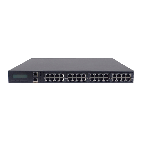
- Page 16 NCA-5210A NCA-5210B NCA-5210C Description LED Indicators Power Status/System Status/Storage Activity LCM with 4x Keypads Management Port 1x RJ45 Management Port Console Port 1x RJ45 Console Port 2x USB 2.0 Type SKU A: 8x RJ45 GbE Ports SKU B: 12x RJ45 GbE Ports SFP Port 2x SFP Port (SKU B only) SKU A/B: 2x NIC Module...
- Page 17 Description PCIe Expansion PCIe Expansion Slots (By Project) 4x Cooling Fans Power Switch 1x Power ON/OFF Switch Power Supply 2x Redundant Power Supply Units Power Jack 2x Power Jacks...
- Page 18 The block diagram indicates how data flows among components on the motherboard. Please refer to the following figure for your motherboard’s layout design.
- Page 19 This layout shows the connectors and jumpers on the board, as a reference of the pin assignments and the internal connectors. PCIE5 FAN1-4 JUSB2 JCOM2 JVGA J80Port ATX1 ATX2 JSPIROM JPMBus JLCM JUSB1 JCOM1 JUSB3 CASEOPEN OPMA SATA3/4 JLOM1 PCIE1 PCIE2 PCIE3 PCIE4...
- Page 20 (3) Install RC-52104A Riser Card on SLOT5 for the use of PCIe x4 in SLOT4 with PCIE x4 in SLOT5. (4) Please use Lanner-manufactured I/O module for the auto configuraiton function that controls PCIe type on SLOT4 and SLOT 5.
- Page 21 SLOT4 x8 SPEG1 SPEG1 SSLOT2 SSLOT2 SSLOT1 SSLOT1 SLOT4 2 x4 SPEG1 SPEG1 SSLOT2 SSLOT2 SSLOT1 SSLOT1 SLOT5 x8 SPEG1 SPEG1 SSLOT2 SSLOT2 SSLOT1 SSLOT1 SLOT5 2 x4 SPEG1 SPEG1 SSLOT2 SSLOT2 SSLOT1 SSLOT1 SLOT4 x4 + SLOT5 x4 SPEG1 SPEG1 SSLOT2 SSLOT2...
-
Page 22: Connector Pin Assignments
Connector Pin Assignments PWBT1: ATX Power ON switch Description SWIN_IN ATX1: 8-pin Power Connector Description +12V +12V +12V +12V ATX2: 24-Pin ATX Power Connector Description Description +3.3V +3.3V +3.3V -12V Ground Ground PSON- Ground Ground Ground Ground Ground Power Good Stand-By 5V +12V +12V... -
Page 23: Pin Description
JSPIROM1: SPIROM BIOS Programming pin header Description Description SPI_CS0- +3.3V SPI_MISO HOLD- SPI_CLK Ground SPI_MOSI JPMBUS1: Redundant PSU PMBUS Connector Description RDPW_TTL1 RDPW_TTL2 PMBUS_CLK PMBUS_DATA JLCM1: 24-Pin LCM w/key Connector Description Description Ground SLIN_N +VEE AFD_N INT_N FL_PD1_R FL_PD0_R FL_PD3_R FL_PD2_R FL_PD5_R FL_PD4_R... - Page 24 JUSB1: USB 2.0 Port1/2 internal pin header Description Description USB1_L_N USB2_L_N USB1_L_P USB2_L_P JCOM1: COM Port1 Console internal pin header Description Description SP1_DCD_A SP1_DSR_A SP1_SIN_A SP1_RTS_A SP1_SOUT_A SP1_CTS_A SP1_DTR_A SP1_RI_A FP_RESET_N JLOM1: LOM port pin header Description Description LAN_MDX0_P LAN_MDX0_N LAN_MDX1_P LAN_MDX1_N LAN_MDX2_P...
- Page 25 SATA1~SATA4: SATA 7-pin signal connectors Description TX_P TX_N RX_N RX_P Note: SATA3/4 is reserved for customization requests. When all SATA ports are used, SLOT2’s support for PCIe will be reduced to only PCIe x4 *1. FAN1~4: 5-Pin CPU FAN connectors Description Ground +12V...
- Page 26 JVGA1: 12-Pin VGA Connector (enabled from the IPMI card) Description Description Ground Ground Ground H-SYNC Ground V-SYNC Ground Detect-display Data Detect-display CLOCK JCOM2: COM PORT 2 internal pin header Description Description MDCDB_N- MDSRB_N MSINB MRTSB_N MSOUTB MCTSB_N MDTRB_N JUSB2: USB 2.0 Port3/4 pin header Description Description USB_VCC...
- Page 27 OPMA1: OPMA Socket CON7 RSVD RSVD OPMA RSVD RSVD DVI_TX0_H LDRQ_L DVI_TX0_L LFRAME_L LAD0 DVI_TX1_H LCLKRUN_L DVI_TX1_L LAD1 LAD2 DVI_TX2_H LAD3 DVI_TX2_L SERIRQ LRST_L DVI_TXCLK_H LCLK DVI_TXCLK_L DVI-I RSVD DVI_DDC_DATA RSVD DVI_DDC_CLK RSVD I2C_PRIV0_SCL ANALOG_DDC_DATA I2C_PRIV0_SDA ANALOG_DDC_CLK I2C_IPMB_SCL ANALOG_RED I2C_IPMB_SDA ANALOG_GREEN ANALOG_BLUE I2C_SB_NIC_SCL...
- Page 28 MSATA1: mSATA socket for storage devices Description Description +3.3V Ground Ground Ground Ground GND5 SATA_RX_P +3.3V SATA_RX_N Ground Ground Ground SMB_SLK SATA_TX_N SMB_DATA SATA_TX_P Ground Ground Ground +3.3V Ground +3.3V Ground DA/DSS Ground Presence Detect +3.3V...
- Page 29 JUSB3: 2 x USB3.0 ports pin header Description Description USB3_RX1_N USB3_RX1_P USB3_RX2_N Ground USB3_RX2_P USB3_TX1_N Ground USB3_TX1_P USB3_TX2_N Ground USB3_TX2_P USB5_N Ground USB5_P USB6_N USB6_P J80PORT1: 80 Port debug Connector (For Factory debug Only) Description Description 80PORTCLK_24M LAD1 LPCRST_N LAD0 LFRAME_N +3.3V LAD3...
- Page 30 To access some components and perform certain service procedures, you must perform the following procedures first. 1. Power off NCA-5210 completely. 2. Remove three (3) screws from each sides and one (1) screw from the rear, as circled in the figures below.
- Page 31 3. Slide and pull the top cover backwards a little bit. 4. Lift the top compartment.
- Page 32 The motherboard supports 1 x 6 Generation Intel CPU (codenamed Skylake) with LGA1151 socket. Please follow the steps below for installing the processor. 1. Locate and press the load lever. 2. Hold and drag the load lever outwards. 3. Drag the load lever out of the latch. 4.
- Page 33 6. Prepare the heat sink. 7. Place the heat sink on top of the CPU socket. 8. Align the four screw holes around the socket. 9. Tighten the four (4) screws to secure the heat sink. 10. Prepare the fan duct. 11.
- Page 34 13. Fold another larger fan duct part as shown. 14. Remove the screw near the fan. 15. Attach C screw hole of the fan duct part to the screw hole near the fan. Secure with the previously removed screw. 16. Place the rest of the fan duct part to the corner of the heatsink.
- Page 35 The motherboard supports DDR4 RDIMM/ECC/UDIMM up to 2,400MHz memory at max. 16GB per socket. Please follow the steps below to install the DIMM memory modules. 1. Power off the system and locate the DDR DIMM slot. 2. Pull open the DIMM slot latches (white tabs) 3.
- Page 36 The system supports 1 x 3.5” or 2 x 2.5” SATA HDDs or SSDs as data storage. Please follow the steps below for installation. 1. Remove the 4 screws that secure the disk drive tray. 2. Remove the tray and mount the hard disk on the tray using the provided disk screws. 3.5”...
- Page 37 3. Secure the disk on the tray using the provided screws with two (2) screws on both sides, and then connect SATA 7-pin signal cable and SATA 15-pin power cable to the installed disk drives. 3.5” SATA HDD/SSD 2.5” SATA HDD/SSD...
- Page 38 4. Place the HDD/SSD mounted disk drive tray back to the system. 5. Please remember to establish SATA connections to the motherboard.
- Page 39 The motherboard provides one mSATA slot. Follow the procedures below for installing a mSATA card. Locate the mSATA socket. 2. Insert a mSATA module as shown in the image below card. Remember to align the module keys between the module and the socket. 3.
- Page 40 The motherboard provides one OPMA socket which is used to install an IPMI card. Please follow the steps below for instructions. Locate the OPMA socket. Insert an IPMI card into the socket and then gently press it down. Remember to align the gold fingers and make sure the two clips securely secure the card.
- Page 41 NCA-5210 supports 2 cooling fans. To replace a worn-down fan, please follow the steps below. 1. Remove the screws circled below. 2. Apply gentle force and pull the fan out of its original place. 3. Install a new fan by reversing the above steps.
- Page 42 NCA-5210 supports one Ethernet NIC module space to expand its network throughput. Please follow the instructions below. For information about compatible modules, please refer to the “Ordering Information” and “Optional Accessories” sections, or contact Lanner for more details. 1. Remove the two lock-screws on the bezel of the module slot and open the bezel.
- Page 43 The system can be installed in a rack, with the slidable rails allowing access to the system while solidly securing the system. Please follow the steps below for installation. Attaching the Short Ear Brackets The Ear Brackets come with six screws, as shown below. Take an ear bracket, align the holes on it with those on the side of the system, and lock it onto the system with the three (3) provided screws.
- Page 44 Attaching Rail Brackets 1. Unpack a slide rail and slide the inner channel to its end. 2. Slide the rail bracket out to its end. 3. To detach the rail bracket from the channel, locate and push the Release Tab on the rail bracket while sliding it out.
- Page 45 Installing the Slide Rail Assemblies 1. This slide-rail kit does NOT require screw-fixing. Aim at three (3) available screw holes on the rack front and lock it by clipping the rail’s front end to the post, as shown in the image below. You should hear a “click” sound once it is firmly attached.
- Page 46 2. Hold the chassis with its front facing you, lift and gently insert it by aligning with the slide-rail assemblies as shown in the image, and then push the unit into the cabinet. 3. Keep sliding the rails in until they stop about halfway. Press down the metal clips on bother inner channels and push them further into the cabinet.
- Page 47 To enter the BIOS setup utility, simply follow the steps below: 1. Boot up the system. 2. Press <Delete> during the boot-up. Your system should be running POST (Power-On-Self-Test) upon booting up. 3. Then you will be directed to the BIOS main screen. 4.
-
Page 48: Bios Information
Main The [Main] is the first setup screen when you enter BIOS. The [Main] displays general system and BIOS information and you may configure “System Date”, and “System Time”. BIOS Information BIOS Vendor: displays BIOS vendor information BIOS Version: displays BIOS version Build Date and Time: displays the date and time the BIOS was built. -
Page 49: Super Io Configuration
Advanced Use [<--] / [-->] to select [Advanced] setup screen. Under this screen, you may use [↑] [↓] to select an item you wish to configure. Super IO Configuration Press “Enter” to access configuration sub-menu for super IO chip parameters. You may access settings for Serial Port 1 or 2 or the Parallel port. -
Page 50: Super Io Configuration - Serial Port 1 Configuration
Once you have entered Super I/O configuration, you may choose to configure Serial Port 1 or 2, or the Parallel port. Super IO Configuration - Serial Port 1 Configuration Press “Enter” to enable or disable the Serial Port 1 (COM). Device setting is fixed as default. -
Page 51: Super Io Configuration - Serial Port 2 Configuration
Super IO Configuration - Serial Port 2 Configuration Once Serial Port 2 is accessed, you may press “Enter” to enable or disable the Serial Port 2 (COM). Device setting is fixed as default. -
Page 52: Parallel Port Configuration
Parallel Port Configuration This option allows you to set parameters for parallel port (LPT/LPTE). Once Parallel Port is accessed, you may press “Enter” to enable or disable the Parallel Port. Device setting is fixed as default. - Page 53 HW Monitor This option allows you to view hardware health status.
-
Page 54: Serial Port Console Redirection
Serial Port Console Redirection This option allows you to configure parameters about serial port console redirection. Press “Enter” to access the submenu. Console Redirection: select “Enabled” or “Disable” for COM port console redirection. The default is “Enabled”. -
Page 55: Com Console Redirection Settings
Console Redirection Settings: select this item to enter the setting sub-menu. COM Console Redirection Settings Terminal Type: the emulation configuration. Select “VT100”, “VT100+”, “VT-UTF8” or “ANSI”. VT100: ASCII character set VT100+: extends VT100 to support color function keys VT-UTF8: uses UTF8 encoding to map Unicode characters onto 1 or more ANSI: Extended ASCII character set... -
Page 56: Bits Per Second
Bits per second: select “9600”, “19200”, “38400”, “57600”, or “115200” for bits per second. The Bps will determine serial port transmission speed. The speed must be matched on the other side. Long or noisy lines may require lower speeds Data Bits: select the value for data bits. -
Page 57: Parity Bits
Parity Bits: a parity bit can be sent with the data bits to detect some transmission errors. Select “None”, “Even”, “Odd”, “Mark” or “Space”. Stop Bits : stop bits indicate the end of a serial data packet. The standard is 1 stop bit. Communication with slow devices may require more than 1. - Page 58 Flow Control: flow control can prevent data loss from buffer overflow. When sending data, if the receiving buffers are full, a “stop” signal can be sent to stop the data flow. You may select “None” or “Hardware RTS/CTS”, depending on the circumstances. VT-UTF8 Combo Key Support: this option enables/disables VT-UTF8 combination key support for ANSI/VT100 terminals.
- Page 59 Putty KeyPad: select Function Key and Key Pad on Putty. You may select “VT100”, “LINUX”, “XTERMR6”, “SCO”, “ESCN”, or “VT400”.
-
Page 60: Cpu Configuration
CPU Configuration This option allows you to configure CPU parameters. Hyper-threading: enabled for Windows XP and Linux (OS optimized for hyper-threading technology) and disabled for other OS that are not optimized for this feature. When enabled, multiple threads will run simultaneously on each logical core. - Page 61 Press “Enter” to choose “Enabled” or “Disabled”. It is recommended to select “Enabled”. Active Processor Cores: number of cores to enable in each processor package. The default is “All” for optimization.
-
Page 62: Execute Disable Bit
You may press “Enter” to select the number of cores to be enabled. It is recommended to select “All” for optimization. Execute Disable Bit: an Intel hardware-based protection against malicious code. It will detect the memory in which a code can be executed or not. When enabled, it will prevent certain classes of malicious buffer overflow attacks when combined with a supporting OS (Windows Server 2003 SP1, Windows XP SP2, SuSE Linux 9.2, RedHat Enterprise 3 Update 3). -
Page 63: Sata Configuration
SATA Configuration Press Enter to access items for SATA devices and settings. SATA Mode Selection: the selection to determine how SATA controllers operate. - Page 64 You may select “AHCI” or “RAID” mode. Please be noted that there must be two SATA disk drives installed in order to enable RAID mode. mSATA: enable or disable the mSATA port...
- Page 65 SATA1: enable or disable the SATA1 port SATA2: enable or disable the SATA2 port...
- Page 66 SATA3: enable or disable the SATA3 port SATA4: enable or disable the SATA4 port...
-
Page 67: Usb Configuration
USB Configuration This option allows you to configure USB device Settings. USB Devices: displays USB devices Legacy USB Support: this function enables or disables legacy USB support. Auto option disables legacy support if no USB devices are connected. Disable option will keep USB devices available only for EFI applications. - Page 68 You may select “Enabled”, “Disabled” or “Auto”.
-
Page 69: Lan Boot Select
LAN Boot Select This option allows you to select one of the onboard LAN boot. Press “Enter” to access the sub-menu. On Board LAN Boot: the default is “Disabled”... - Page 70 Chipset Use [<--] / [-->] to select [Chipset] setup screen. Under this screen, you may use [↑] [↓] to select “System Agent (SA) Configuration” or “PCH-IO Configuration”. displays and provides options to configure system agent (SA) parameters VT-d: select “Enabled” or “Disabled” for Intel VT-d virtualization function.
-
Page 71: Memory Configuration
Memory Configuration Memory Configuration provides memory configuration parameters. -
Page 72: Pch-Io Configuration
Once accessed, information about memory frequency, total memory, and DIMM#1-4 status will be displayed. PCH-IO Configuration PCH-IO configuration provides PCH parameters. - Page 73 Intel PCH RC Version: displays Intel PCH RC version Intel PCH SKU Name: displays PCH SKU name Intel PCH Rev ID: displays Intel PCH revision ID Restore On Power Loss: select “Restore On Power Loss” options: Power On, Power Off, or Last Status.
- Page 74 Security Use [<--] / [-->] to select [Security] setup screen. Under this screen, you may use [↑] [↓] to select an item you want to configure. Administrator Password: set administrator password. Once set, then this only limits access to Setup and is only asked for when entering Setup.
-
Page 75: Boot Mode Select
Boot Use [<--] / [-->] to select [Boot] setup screen. Under this screen, you may use [↑] [↓] to select an item you want to configure. Boot mode select: select boot mode LEGACY or UEFI. - Page 76 Boot Option #1: determine the device to be the first system boot device. Boot Option #2: determine the device to be the second system boot device.
- Page 77 Boot Option #3: determine the device to be the third system boot device. USB Device BBS Priorities: specifies the boot device priority sequence from available USB drives.
-
Page 78: Boot Option
Boot Option #1: set the device to be the first system boot device. Boot Option #2: determine the device to be the second system boot device. - Page 79 Boot Option #3: determine the device to be the third system boot device. Boot Option #4: determine the device to be the fourth system boot device.
-
Page 80: Save And Exit
Save & Exit Use [<--] / [-->] to select [Save & Exit] setup screen. Under this screen, you may use [↑] [↓] to select an item you want to configure. Save Changes and Exit: exit system setup after saving the configuration changes Discard Changes and Exit: exit system setup without saving the configuration changes Restore Defaults:... - Page 81 Discard Changes and Exit: exit system setup without saving the configuration changes...
- Page 82 Restore Defaults: restore/load factory default setting for all setup parameters.
-
Page 83: Boot Override
Boot Override You may select a device under “Boot Override” for this function. -
Page 85: Appendix A: Programming Watchdog Timer
APPENDIX A: PROGRAMMING WATCHDOG TIMER A watchdog timer is a piece of hardware that can be used to automatically detect system anomalies and reset the processor in case there are any problems. Generally speaking, a watchdog timer is based on a counter that counts down from an initial value to zero. -
Page 86: Appendix B: Setting Up Console Redirection
APPENDIX B: SETTING UP CONSOLE REDIRECTION Console redirection lets you monitor and configure a system from a remote terminal computer by re- directing keyboard input and text output through the serial port. These following steps illustrate how to use this feature. The BIOS of the system allows the redirection of console I/O to a serial port. With this configured, you can remotely access the entire boot sequence through a console port. -
Page 87: Appendix C: Programming Generation
“Normal” and another is “Bypass” status. Furthermore, the Lanner Bypass software is capable to control the bypass status in the following 3 instances. 1. When the system powers off, it can be forced to enable the LAN Bypass function. -
Page 88: Appendix D: Programming The Lcm
2 lines, 16 (or 20) characters per line. • USB and Serial Text or Graphic-based LCM: Our next generation LCM. Lanner engineers design a common source code to be deployed on these two differently interfaced LCM modules. Jumpers are used to select between text and graphic types. - Page 89 Display Off turning off the LCM display Cursor Off/On NOT showing/showing the cursor on the LCM display Blinking off/On turning off/on the cursor blinking Writing “Lanner@Taiwan” displaying the specific sentences Reading “Lanner@Taiwan” reading the specific sentence CGram Test displaying the user-stored characters...
- Page 90 -LCM2 — Writing “2013-11-05” in line 2. — To execute, please type: #./plcm_test -LCM2 Keypad — Get the keypad input: the 1st button is read in as Left, the 2nd button is read in as Up, the 3rd button is read in as Right, and the 4th button is read in as Down.
- Page 91 Here, we take the Fedora 20 x86_64 operation system for instance to explain 3 virtualization respectively for parallel port pass through. Use the procedures listed below for step-by-step instructions separately based on your case. In case of QEMU/KVM or Xen, please use the following steps as a guideline to implement the virtualization : (1) Make sure that the Guest OS has been installed.
-
Page 92: Appendix E: Peg Port Configuration For Alternative Cpu
APPENDIX E: PEG PORT CONFIGURATION FOR ALTERNATIVE CPU This configuration is dedicated for a Kaby Lake processor going with LAN module IQM201. Follow the instructions in 錯誤! 找不到參照來源。 to enter the BIOS setup utility. Use [<--] / [-->] to select [Chipset] setup screen. Under this screen, use [↑] [↓] to select and enter “System Agent (SA) Configuration”. -
Page 94: Appendix F: Terms And Conditions
APPENDIX F: TERMS AND CONDITIONS Warranty Policy 1. All products are under warranty against defects in materials and workmanship for a period of one year from the date of purchase. 2. The buyer will bear the return freight charges for goods returned for repair within the warranty period; whereas the manufacturer will bear the after service freight charges for goods returned to the user. - Page 95 When requesting RMA service, please fill out the following form. Without this form enclosed, your RMA cannot be processed.
Need help?
Do you have a question about the NCA-5210 and is the answer not in the manual?
Questions and answers